EP0984264A2 - Verfahren und Vorrichtung zur Messung der Bearbeitbarkeit und Bearbeitungsgeschwindigkeit von einem Material - Google Patents
Verfahren und Vorrichtung zur Messung der Bearbeitbarkeit und Bearbeitungsgeschwindigkeit von einem Material Download PDFInfo
- Publication number
- EP0984264A2 EP0984264A2 EP99306819A EP99306819A EP0984264A2 EP 0984264 A2 EP0984264 A2 EP 0984264A2 EP 99306819 A EP99306819 A EP 99306819A EP 99306819 A EP99306819 A EP 99306819A EP 0984264 A2 EP0984264 A2 EP 0984264A2
- Authority
- EP
- European Patent Office
- Prior art keywords
- piercing
- pierce
- machinability
- machining
- time duration
- Prior art date
- Legal status (The legal status is an assumption and is not a legal conclusion. Google has not performed a legal analysis and makes no representation as to the accuracy of the status listed.)
- Withdrawn
Links
Images


Classifications
-
- B—PERFORMING OPERATIONS; TRANSPORTING
- B24—GRINDING; POLISHING
- B24C—ABRASIVE OR RELATED BLASTING WITH PARTICULATE MATERIAL
- B24C7/00—Equipment for feeding abrasive material; Controlling the flowability, constitution, or other physical characteristics of abrasive blasts
- B24C7/0046—Equipment for feeding abrasive material; Controlling the flowability, constitution, or other physical characteristics of abrasive blasts the abrasive material being fed in a gaseous carrier
- B24C7/0053—Equipment for feeding abrasive material; Controlling the flowability, constitution, or other physical characteristics of abrasive blasts the abrasive material being fed in a gaseous carrier with control of feed parameters, e.g. feed rate of abrasive material or carrier
-
- B—PERFORMING OPERATIONS; TRANSPORTING
- B24—GRINDING; POLISHING
- B24C—ABRASIVE OR RELATED BLASTING WITH PARTICULATE MATERIAL
- B24C1/00—Methods for use of abrasive blasting for producing particular effects; Use of auxiliary equipment in connection with such methods
- B24C1/04—Methods for use of abrasive blasting for producing particular effects; Use of auxiliary equipment in connection with such methods for treating only selected parts of a surface, e.g. for carving stone or glass
- B24C1/045—Methods for use of abrasive blasting for producing particular effects; Use of auxiliary equipment in connection with such methods for treating only selected parts of a surface, e.g. for carving stone or glass for cutting
-
- B—PERFORMING OPERATIONS; TRANSPORTING
- B24—GRINDING; POLISHING
- B24C—ABRASIVE OR RELATED BLASTING WITH PARTICULATE MATERIAL
- B24C7/00—Equipment for feeding abrasive material; Controlling the flowability, constitution, or other physical characteristics of abrasive blasts
- B24C7/0046—Equipment for feeding abrasive material; Controlling the flowability, constitution, or other physical characteristics of abrasive blasts the abrasive material being fed in a gaseous carrier
- B24C7/0076—Equipment for feeding abrasive material; Controlling the flowability, constitution, or other physical characteristics of abrasive blasts the abrasive material being fed in a gaseous carrier the blasting medium being a liquid stream
-
- G—PHYSICS
- G01—MEASURING; TESTING
- G01N—INVESTIGATING OR ANALYSING MATERIALS BY DETERMINING THEIR CHEMICAL OR PHYSICAL PROPERTIES
- G01N3/00—Investigating strength properties of solid materials by application of mechanical stress
- G01N3/56—Investigating resistance to wear or abrasion
- G01N3/567—Investigating resistance to wear or abrasion by submitting the specimen to the action of a fluid or of a fluidised material, e.g. cavitation, jet abrasion
-
- G—PHYSICS
- G01—MEASURING; TESTING
- G01N—INVESTIGATING OR ANALYSING MATERIALS BY DETERMINING THEIR CHEMICAL OR PHYSICAL PROPERTIES
- G01N3/00—Investigating strength properties of solid materials by application of mechanical stress
- G01N3/58—Investigating machinability by cutting tools; Investigating the cutting ability of tools
Definitions
- This invention relates generally to machining methods and apparatus and more particularly to methods and apparatus for abrasive waterjet machining of engineering materials.
- the machinability number is a property of a specific material which varies depending on the type of machinery operation, such as milling, to be performed and is related to a number of materials properties.
- the machinability number is related primarily to flow stress of the material.
- the machinability is related to the fracture energy, grain size (or flow distribution for materials such as glass), modulus of elasticity and Poisson's ratio.
- Some AWJ systems manufacturers and their customers have attempted addressing the problem of determining the machinability numbers of materials by providing databases of machinability number data from trial-and-error, empirical tests performed by experienced AWJ operators on specific customer materials. This, however, involves considerable effort which is both costly and time-consuming. Such databases are also cumbersome and tedious to use.
- the development of computer software has facilitated the use of databases of empirically obtained machinability number data to calculate the optimum operating criteria for materials for which the machinability number has been previously obtained.
- the computer software may also be used to guide and assist an operator in conducting the empirical tests required to determine the machinability number from test pieces of the material.
- the trial-and-error testing required to obtain machinability number data is wasteful, however, because it requires the use of numerous test pieces of material. Moreover, the testing is costly and time-consuming because it requires an AWJ machine operator to manually perform and evaluate the results of the testing, input the resultant empirical results, and program the machining parameters required for a subsequent machining operation to be performed.
- a method for measuring the machinability of a material comprising the steps of:
- a method for determining the machining speed of a material comprising the steps of:
- machining a material comprising the steps of:
- Fig. 1 shows a broad system diagram of an embodiment as applied to an abrasive waterjet (AWJ) system.
- Abrasive water jet (AWJ) processes employ abrasive materials entrained into a high-pressure waterjet to perform a variety of milling and other machining operations on a variety of materials.
- the high-energy waterjet beam utilises combines a rapid erosion of a workpiece material by high speed solid particle impacts with rapid cooling provided by a waterjet.
- an abrasive waterjet removes material over a designated area at precisely controlled depths.
- a nozzle assembly 10 comprising an orifice 12 and a focussing tube 14 which applies a mixture of high pressure water and abrasive to a moving workpiece 16.
- the nozzle assembly 10 is preferably supplied with abrasive from an optional vibration feeder 20 and high pressure water from a water source 22. Although shown using a vibration feeder, other types of feeding devices may be used for this purpose.
- a controlling unit 30 which controls the feed from vibration feeder 20 and the feed supply of high pressure water from the water source 22. Prior to performing an AWJ milling operation, the controlling unit 30 is typically preset by a user with the AWJ system operating parameters including "d o ", "d f ", "P", "A”, and "D". The selection of these operating parameters for performing milling operations using an AWJ apparatus are described below.
- controlling unit 30 receives input on the operating conditions of the AWJ system and calculates optimum milling speeds "u m " for the material of the workpiece 16 and accordingly controls the motion of the workpiece 16 to provide the desired speed.
- the controlling unit 30 is preferably a Computerised Numerical Controller (CNC) and may include, e.g. a Model ACR 2000 motion controller which is available from Acroloop Motion Control Systems, Inc., Chanhassen, MN, U.S.A.
- Eqn. 1 is also conditioned upon using a lateral feed (i.e side movement of nozzle between each parallel pass) set to (2/3).d f .
- the machinability number "N mm " depends upon the type of the material upon which a milling operation is to be performed. Because the machinability number is a property of a specific material, it must be determined prior to performing a milling operation on a workpiece made of a type of material which has not been milled before. The need for predetermining a machinability number for a material by multiple trial-and-error tests prior to performing a machining operation may be eliminated by the automatic machinability measuring and machining methods and the apparatus therefor provided herein.
- the present inventor has ascertained that the machinability number "N mm " for a milling operation on a material is inversely related to the time "T” required by an AWJ waterjet to pierce through a material using a linear piercing motion having a thickness "h” according to the following empirical equation: where “C tm " is a constant (which is 189,236 when calculating milling speed using dimensions for an inch-unit system) and "P” is the waterjet pressure (ksi); “d o “ is the bore diameter (inches) of orifice 12; “d f “ is the bore diameter (inches) of the focussing tube 14; “A” is the abrasive flow rate (lbs/min) to be provided to the nozzle assembly 10 by the vibration feeder 20.
- the machinability number for milling can be automatically calculated for the workpiece based upon the piercing time.
- the thickness "h” is dictated by the size of the workpiece to be milled and is measured and inputted into controlling unit 30 either manually by a user or automatically using a thickness sensor as described below.
- the nozzle assembly 10 includes a nozzle shield 15 surrounding the focussing tube 14.
- the nozzle shield 15 is connected to and in fluid communication with an air or other gas supply 40 via a conduit 41.
- a pressure sensor 42 is connected to the conduit 41 and located between the nozzle shield 15 and air supply 40 for sensing the pressure conditions inside the nozzle shield 15 and providing a pressure sensor signal 43 to the controlling unit 30.
- the controlling unit 30 is activated in Step 300 by inputting the specific AWJ system operating parameters including "d o ", "D f ", "P” and "A".
- the controlling unit 30 upon receiving a user instruction to begin a milling sequence, begins a piercing cycle in Step 310 by generating a control signal 39 in Step 310 to the air supply 40 thereby initiating airflow into the nozzle shield 15 via the conduit 41.
- the controlling unit 30 generates a control signal 11 instructing motion equipment (not shown) to the lower nozzle assembly in Step 320 to form an air gap 17 having a predetermined height which is approximately equal to the stand-of distance (i.e. the distance between the focussing tube 14 and workpiece 16).
- Step 330 This is accomplished by using the pressure sensor 42 as a proximity switch which monitors in Step 330 the pressure increase caused by the restriction created between the workpiece 16 and nozzle shield 15 as it moves toward the target surface.
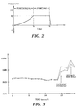
- the stand-off and air gap distances are established by first establishing a known-air gap distance which, as shown in Fig. 2, corresponds to a predetermined pressure P g , which value is programmed into controlling unit 30.
- the controlling unit 30 When in Step 330 it is detected that the pressure inside nozzle shield 15 has reached the predetermined pressure P g , the controlling unit 30 generates a control signal to stop the motion of the nozzle assembly 10 in Step 340 to set the desired stand-off distance.
- Step 350 the controlling unit 30 simultaneously generates control signals 21 and 19 to initiate, respectively, the supply of high pressure water from the water source 22 and abrasive from the vibration feeder 20 to establish an abrasive water jet in the water nozzle assembly 10.
- the controlling unit 30 also begins a timing sequence and sends a control signal 11 to move the nozzle assembly 10 at a constant rate (e.g. 50 inches per minute - 127cm/min) along a circle which, preferably, has a radius equal to the focussing tube diameter, "D f ", until the workpiece 16 is pierced.
- a constant rate e.g. 50 inches per minute - 127cm/min
- the air supply 40 continues to provide a steady flow of air to the nozzle shield 15 while the pressure sensor 42 monitors and provides a steady output signal 43 to the controlling unit 30 as represented by the horizontal signal between "t g " and T p ".
- a vacuum is created within the nozzle shield 15 which, as shown in Fig. 2, causes a virtually instantaneous drop in the pressure detected by the pressure sensor 42 at "t p ", which is the moment pierce-through occurs.
- Step 360 Upon detecting the decrease in pressure in Step 360 caused upon pierce-through, the controlling unit 30 stops the timing sequence in Step 370 and obtains and records the pierce-through time "T". In Step 375, the controlling unit 30 calculates the machinability number "N mm " for milling according to Eqn. 1 set forth above which is programmed into controlling unit 30.
- the workpiece 16 to be milled is then placed under the nozzle assembly 10.
- the desired depth "D" of the material to be removed from the workpiece is programmed into the controlling unit 30 and a counter is set to zero in Step 380 for tracking the number of milling passes made by the nozzle assembly 10.
- the controlling unit 30 Upon receiving a user instruction in Step 390 to begin a milling sequence, the controlling unit 30 generates a control signal 11 instructing motion equipment (not shown) to position the nozzle assembly 10 in Steps 400, 410 and 415 to establish stand-off and air gap distances over the workpiece 16 in the same manner as described in Steps 320, 330 and 340, respectively, for the piercing operating above.
- Step 410 when in Step 410 it is detected that the pressure inside the nozzle shield 15 has reached the predetermined pressure P g , the controlling unit 30 generates a control signal to reverse the motion of the nozzle assembly 10 in Step 340 to set the desired stand-off distance.
- the thickness "h" of the workpiece 16 may be automatically measured and inputted into the controlling unit 30. This is accomplished in Step 420 by comparing the height of nozzle assembly in the cutting position with a known reference position and calculating the thickness of the workpiece. Alternatively, the thickness "h” may be measured manually by the operator and inputted into the controlling unit 30 in Step 420.
- Step 460 The value of "D" is then reset to equal the bore diameter of the focussing tube 14, "d f " in step 440 and the traverse speed "U m " for the overlapped milling passes is calculated in Step 460 according to Eqn. 1 set forth above.
- Step 430 If, however, in Step 430 the desired depth "D" is smaller than or equal to "d f ", then in Step 450, "N" is set to equal one and the desired depth “D” is used in Step 460 along with the stored machinability number N mm to calculate the traverse speed "U m " according to Eqn. 1 set forth above.
- controlling uni 30 may be programmed to check the calculated traverse speed "U m " required against a maximum speed "U max " which is the limit of the AWJ apparatus limit of speed. If U m >U max , then controlling unit 30 prevents the milling operation and generates an error message that the operation is not feasible.
- Step 470 The desired milling operation is then initiated in Step 470 by the controlling unit 30 which simultaneously generates control signals 21 and 19 to initiate, respectively, the supply of high pressure water from the water source 22 and abrasive from the vibration feeder 20 to establish an abrasive water jet in the water nozzle assembly 10.
- the controlling unit 30 also sends a control signal 11 to begin the movement of nozzle assembly 10 and/or a control signal 26 to begin the movement of the workpiece 16 at the calculated milling speed "U m ".
- a mask is cut based on a CAD file of the workpiece part and used to protect and to achieve a better edge quality in the surrounding workpiece material which is not to be milled.
- the milling process may comprise parallel passes to cover a desired milling area.
- the controlling unit 30 is programmed to perform both multiple parallel passes and multiple layers of passes to cover the desired milling area and depth of milling.
- Step 480 When controlling unit detects in Step 480 that one layer of the milling operation is complete, the counter in step 510 is increased by one and then compared in Step 520 to determine whether the desired set number of milling layers "N" has been performed. If not, then the milling operation repeats by the controlling unit 30 resetting the nozzle position by moving the nozzle assembly 10 and/or workpiece 16 in step 530 and returning to begin another milling layer in Step 470. The milling process is continued until the desired number of milling layers, "N", have been performed and detected in Step 520 at which point the milling operation is ended.
- the milling operation is described as including a preliminary piercing test on a testpiece which is separated from a workpiece 16 to be subsequently milled, thus requiring the testpiece to be replaced by the workpiece between steps 375 and 30.
- a test coupon may be provided on the workpiece so that the milling operation may be performed immediately following the piercing operation. The test coupon may then be cut off after the AWJ milling operation is complete.
- a typical device includes a Model OKC-424 Air Proximity Sensor, available from O'Keefe Controls Co., Monroe, CT, U.S.A.
- pierce-through detectors 50 and 55 which, respectively, may be attached to or used in the vicinity of a workpiece 16 upon which an AWJ operation is being performed.
- the pierce-through detectors 50 and 55 may be used individually or in combination.
- Typical detectors which may be used in this fashion include conventional sensors, which can either directly detect the presence of the waterjet upon pierce-through (e.g. by means of an optical sensor) or indirectly detect some characteristic change which occurs upon pierce through (e.g. by means of an acoustic sensor or a load cell).
- Acoustic sensors useful in this regard are those which can detect the change in sound level which occurs upon pierce through and include an acoustic sensor such as the Model 2800 Integrating Sound Level Meter available from Quest Technologies, Inc., Oconomowoc, WI, U.S.A. Shown in Fig. 3 is a reproduction of the acoustic readings obtained during an AWJ piercing operation using an acoustic sensor with the initiation of the waterjet operation and the moment of pierce-through clearly indicated by two separate and distinct peaks.
- an acoustic sensor such as the Model 2800 Integrating Sound Level Meter available from Quest Technologies, Inc., Oconomowoc, WI, U.S.A. Shown in Fig. 3 is a reproduction of the acoustic readings obtained during an AWJ piercing operation using an acoustic sensor with the initiation of the waterjet operation and the moment of pierce-through clearly indicated by two separate and distinct peaks.
- Load cells also useful in this regard are those which can detect the decrease in the force exerted on the workpiece 16 by a waterjet which occurs upon pierce-through and may include load cells such as those available from Sens-All, Inc., Southington, CT, U.S.A.
- a conventional mechanical switch 60 may be located directly under workpiece 16 such that upon penetration by the waterjet, the switch 60 is tripped thereby indicating to the controlling unit 30 by signal 61 of the existence of a pierce-through condition.
- an AWJ system which provides a number of advantages over known milling and other machining processes. Among these advantages is the ability to determine using the present automated machining processes which determine the optimum machining parameters for an AWJ operation without the need for multiple trial-and-error testing or extensive user experience for machining new materials.
- a continuous milling process may be provided by incorporating a test coupon on the workpiece. By sequentially piercing a test hole in the test coupon and proceeding without interruption to a milling operation, a continuous milling operation may be achieved. The test piece is later removed by cutting.
- machining speeds during operation may be accomplished without the need for any user interference or interface while also increasing the accuracy of the optimum machining speeds so determined.
- various control and measurement functions may be automatically accomplished using the present apparatus and method including proximity detection of a workpiece with respect to a waterjet nozzle and measuring the thickness of a workpiece. Additionally, compensation for changes in process parameters (e.g. changes in water pressure, abrasive flow rate, abrasive type, nozzle diameter, etc.) may also be made automatically.
- the present apparatus and method may be used for determining the machinability numbers using other energy beam machining technologies in addition to AWJ milling processes. Moreover, it is envisaged that the determination of machinability numbers of engineering material using one energy beam process may be applied to or otherwise correlated with calculating process parameters for use in other types of energy beam machining processes.
- Such energy beam technologies include those which utilise a concentrated beam energy to effect material removal to cut or otherwise make, shape, prepare or finish (i.e. machine) a raw stock material into a finished material.
- the apparatus and method may be adapted for incorporation into other types of energy beam technologies, including pure waterjet, laser, plasma arc, flame cutting and electron beam technologies. Although each of these use different physical phenomena to remove material, they behave similarly in nature and methodology to a waterjet energy beam such that the present apparatus and method may be employed.
- AWJ Energy Delivery Relationships: AWJ The higher the applied flow/pressure (hp/watts), the faster the material removal rate. Laser The higher the applied output power (hp/watts), the faster the material removal rate. Plasma The higher the applied flow/pressure (hp/watts), the faster the material removal rate.
- AWJ Machining (e.g. milling, turning) removal rates can be related to a machinability number. Laser Machining removal rates can be related to a machinability number.
- the present method and apparatus may be used to determine the machinability number for other energy beam processes (e.g. laser and plasma energy beam processes) which cause material responses similar to those set forth above for a waterjet process.
- energy beam processes including AWJ may be used to perform a variety of other AWJ and traditional operations such as piercing, drilling and turning operations.
Landscapes
- Engineering & Computer Science (AREA)
- Mechanical Engineering (AREA)
- Immunology (AREA)
- Pathology (AREA)
- Analytical Chemistry (AREA)
- Biochemistry (AREA)
- General Health & Medical Sciences (AREA)
- General Physics & Mathematics (AREA)
- Physics & Mathematics (AREA)
- Chemical & Material Sciences (AREA)
- Life Sciences & Earth Sciences (AREA)
- Health & Medical Sciences (AREA)
- Perforating, Stamping-Out Or Severing By Means Other Than Cutting (AREA)
- Machine Tool Sensing Apparatuses (AREA)
- Investigating Strength Of Materials By Application Of Mechanical Stress (AREA)
- Force Measurement Appropriate To Specific Purposes (AREA)
Applications Claiming Priority (2)
| Application Number | Priority Date | Filing Date | Title |
|---|---|---|---|
| US143822 | 1998-08-31 | ||
| US09/143,822 US6021682A (en) | 1998-08-31 | 1998-08-31 | Automatic machinability measuring and machining methods and apparatus therefor |
Publications (2)
| Publication Number | Publication Date |
|---|---|
| EP0984264A2 true EP0984264A2 (de) | 2000-03-08 |
| EP0984264A3 EP0984264A3 (de) | 2001-01-24 |
Family
ID=22505815
Family Applications (1)
| Application Number | Title | Priority Date | Filing Date |
|---|---|---|---|
| EP99306819A Withdrawn EP0984264A3 (de) | 1998-08-31 | 1999-08-27 | Verfahren und Vorrichtung zur Messung der Bearbeitbarkeit und Bearbeitungsgeschwindigkeit von einem Material |
Country Status (3)
| Country | Link |
|---|---|
| US (1) | US6021682A (de) |
| EP (1) | EP0984264A3 (de) |
| JP (1) | JP2000218544A (de) |
Cited By (8)
| Publication number | Priority date | Publication date | Assignee | Title |
|---|---|---|---|---|
| RU2213954C1 (ru) * | 2002-03-25 | 2003-10-10 | Открытое акционерное общество "АВТОВАЗ" | Способ оценки технологической эффективности смазочно-охлаждающей жидкости |
| RU2473070C1 (ru) * | 2011-06-24 | 2013-01-20 | Федеральное государственное образовательное учреждение высшего профессионального образования "Челябинская государственная агроинженерная академия" | Способ контроля износа узлов трения |
| TWI420108B (zh) * | 2009-09-21 | 2013-12-21 | China Steel Corp | Evaluation Method for Impact Capacity of High Pressure Water Sprayer and Sprayer |
| CN108106955A (zh) * | 2017-12-14 | 2018-06-01 | 中国特种飞行器研究所 | 一种大流量、高速水冲刷试验方法 |
| EP3441186A1 (de) * | 2017-08-08 | 2019-02-13 | D.E.C.O. Nv | Wasserstrahlvorrichtung mit durchflusssensor und verfahren zum wasserstrahlschneiden |
| CN110153707A (zh) * | 2019-04-25 | 2019-08-23 | 孙树峰 | 一种激光-喷射液束自生磨粒流复合加工装置及方法 |
| CN110153708A (zh) * | 2019-04-25 | 2019-08-23 | 孙树峰 | 一种激光-喷射液束自生磨粒流复合加工头及工作方法 |
| WO2023278430A1 (en) * | 2021-06-29 | 2023-01-05 | Shape Technologies Group, Inc. | Fluid jet systems and methods of use to access and disassemble components hazardous articles |
Families Citing this family (23)
| Publication number | Priority date | Publication date | Assignee | Title |
|---|---|---|---|---|
| US6622058B1 (en) | 2000-04-10 | 2003-09-16 | Tate S. Picard | Centralized control architecture for a plasma arc system |
| US6772040B1 (en) * | 2000-04-10 | 2004-08-03 | Hypertherm, Inc. | Centralized control architecture for a plasma arc system |
| US6947802B2 (en) * | 2000-04-10 | 2005-09-20 | Hypertherm, Inc. | Centralized control architecture for a laser materials processing system |
| US6359251B1 (en) | 2000-04-10 | 2002-03-19 | Hypertherm, Inc. | Centralized control architecture for a plasma arc system |
| US7186947B2 (en) * | 2003-03-31 | 2007-03-06 | Hypertherm, Inc. | Process monitor for laser and plasma materials processing of materials |
| US20060163220A1 (en) * | 2005-01-27 | 2006-07-27 | Brandt Aaron D | Automatic gas control for a plasma arc torch |
| EP2243594A1 (de) * | 2009-04-20 | 2010-10-27 | Univerza v Ljubljani | Anordnung von Vorrichtungen und Verfahren zur empirischen Bestimmung eines Effizienz-Index im Abrasiv-Wasserstrahlschneiden und deren Anwendung in einer Vorrichtung zur gleichzeitigen Steuerung beim Abrasiv-Wasserstrahlschneiden |
| KR101057990B1 (ko) | 2009-05-21 | 2011-08-19 | 한국과학기술원 | 초고압 워터젯을 이용한 암반 굴착 모사 시험 장치 |
| CZ305514B6 (cs) * | 2010-07-23 | 2015-11-11 | Ăšstav geoniky AV ÄŚR, v. v. i. | Způsob stanovení konstanty hydroabrazivní dělitelnosti materiálu Kawj |
| CZ305547B6 (cs) * | 2010-07-23 | 2015-12-02 | Ăšstav geoniky AV ÄŚR, v. v. i. | Způsob stanovení konstanty hydroabrazivní dělitelnosti materiálu Kawj [μm] |
| CN102288503B (zh) * | 2011-07-12 | 2013-08-14 | 中国石油大学(北京) | 一种模拟高压管汇的冲蚀试验机 |
| DE102011051790A1 (de) * | 2011-07-12 | 2013-01-17 | Haver & Boecker Ohg | Vorrichtung und Verfahren zur Bestimmung einer Verschleißfestigkeit von Gewebe |
| WO2014052407A1 (en) * | 2012-09-25 | 2014-04-03 | G.D.O. Inc. | Underwater abrasive entrainment waterjet cutting |
| EP2740574A1 (de) * | 2012-12-04 | 2014-06-11 | Siemens Aktiengesellschaft | Vorrichtung und akustisch überwachte Wasserstrahlverfahren |
| US10744620B2 (en) * | 2017-09-21 | 2020-08-18 | Shape Technologies Group, Inc. | Air flow management systems and methods to facilitate the delivery of abrasives to an abrasive fluid jet cutting head |
| EP3486027B1 (de) * | 2017-11-21 | 2022-12-28 | Synova S.A. | Messung eines flüssigkeitsstrahls zur führung eines laserstrahls |
| US12350789B2 (en) * | 2017-12-20 | 2025-07-08 | Flow International Corporation | Fluid jet nozzles and methods of making same |
| US11554461B1 (en) | 2018-02-13 | 2023-01-17 | Omax Corporation | Articulating apparatus of a waterjet system and related technology |
| BE1026552B1 (nl) * | 2018-08-20 | 2020-03-19 | Genr8 Bvba | Partikelstraaltoestel |
| CN209247562U (zh) * | 2018-10-25 | 2019-08-13 | 西南交通大学 | 一种用于盾构刀盘刀具磨耗特性测试试验装置 |
| CN111665188A (zh) * | 2019-03-06 | 2020-09-15 | 科思创德国股份有限公司 | 一种测试材料耐化学性能的方法 |
| CN113376044B (zh) * | 2021-06-10 | 2022-07-12 | 中国兵器工业第五九研究所 | 一种高温高压气体冲刷实验装置 |
| CN115213820A (zh) * | 2022-08-03 | 2022-10-21 | 北华航天工业学院 | 一种非淹没状态下高压磨料水射流切割装置 |
Family Cites Families (10)
| Publication number | Priority date | Publication date | Assignee | Title |
|---|---|---|---|---|
| US3974678A (en) * | 1975-03-05 | 1976-08-17 | Conchemco, Incorporated | Automatic paint cure tester |
| JPH0627303B2 (ja) * | 1985-07-24 | 1994-04-13 | 愛知製鋼株式会社 | 冷間鍛造用軟磁性ステンレス鋼 |
| US4941955A (en) * | 1987-07-06 | 1990-07-17 | The Interlake Companies, Inc. | Apparatus and method for electrochemical machining of flat plates or sheets |
| US4966059A (en) * | 1987-09-22 | 1990-10-30 | First Brands Corporation | Apparatus and process for high speed waterjet cutting of extensible sheeting |
| DE3903133A1 (de) * | 1988-02-04 | 1989-08-31 | Amada Co | Werkstueckbearbeitbarkeitsdetektionsverfahren und verfahren zum spanabhebenden bearbeiten eines werkstuecks mit hilfe einer spanabhebenden bearbeitungsmaschine unter anwendung dieses verfahrens |
| DE3942299C2 (de) * | 1989-12-21 | 1995-04-27 | Bosch Gmbh Robert | Verfahren und Vorrichtung zum laufenden Messen der Größe von Durchgangsbohrungen |
| EP0444974A1 (de) * | 1990-02-01 | 1991-09-04 | Gaz De France | Verfahren und Vorrichtung zum Auswechseln von im Erdreich verlegten Rohrleitungen |
| US5045669A (en) * | 1990-03-02 | 1991-09-03 | General Electric Company | Method and apparatus for optically/acoustically monitoring laser materials processing |
| JP2868384B2 (ja) * | 1993-02-23 | 1999-03-10 | 株式会社東京精密 | ダイシング溝の深さ測定方法及びダイシング装置 |
| GB2307917B (en) * | 1995-12-08 | 1999-03-17 | Hitachi Powdered Metals | Manufacturing process of sintered iron alloy improved in machinability,mixed powder for manufacturing modification of iron alloy and iron alloy product |
-
1998
- 1998-08-31 US US09/143,822 patent/US6021682A/en not_active Expired - Fee Related
-
1999
- 1999-08-27 EP EP99306819A patent/EP0984264A3/de not_active Withdrawn
- 1999-08-31 JP JP11244226A patent/JP2000218544A/ja active Pending
Cited By (12)
| Publication number | Priority date | Publication date | Assignee | Title |
|---|---|---|---|---|
| RU2213954C1 (ru) * | 2002-03-25 | 2003-10-10 | Открытое акционерное общество "АВТОВАЗ" | Способ оценки технологической эффективности смазочно-охлаждающей жидкости |
| TWI420108B (zh) * | 2009-09-21 | 2013-12-21 | China Steel Corp | Evaluation Method for Impact Capacity of High Pressure Water Sprayer and Sprayer |
| RU2473070C1 (ru) * | 2011-06-24 | 2013-01-20 | Федеральное государственное образовательное учреждение высшего профессионального образования "Челябинская государственная агроинженерная академия" | Способ контроля износа узлов трения |
| EP3441186A1 (de) * | 2017-08-08 | 2019-02-13 | D.E.C.O. Nv | Wasserstrahlvorrichtung mit durchflusssensor und verfahren zum wasserstrahlschneiden |
| BE1025457B1 (nl) * | 2017-08-08 | 2019-03-11 | D.E.C.O. Nv | Waterstraalinrichting en methode voor het detecteren van een insnijding |
| CN108106955A (zh) * | 2017-12-14 | 2018-06-01 | 中国特种飞行器研究所 | 一种大流量、高速水冲刷试验方法 |
| CN110153707A (zh) * | 2019-04-25 | 2019-08-23 | 孙树峰 | 一种激光-喷射液束自生磨粒流复合加工装置及方法 |
| CN110153708A (zh) * | 2019-04-25 | 2019-08-23 | 孙树峰 | 一种激光-喷射液束自生磨粒流复合加工头及工作方法 |
| CN110153708B (zh) * | 2019-04-25 | 2020-06-05 | 孙树峰 | 一种激光-喷射液束自生磨粒流复合加工头及工作方法 |
| CN110153707B (zh) * | 2019-04-25 | 2020-06-16 | 孙树峰 | 一种激光-喷射液束自生磨粒流复合加工装置及方法 |
| WO2023278430A1 (en) * | 2021-06-29 | 2023-01-05 | Shape Technologies Group, Inc. | Fluid jet systems and methods of use to access and disassemble components hazardous articles |
| EP4363161A4 (de) * | 2021-06-29 | 2025-05-07 | Shape Technologies Group, Inc. | Flüssigkeitsstrahlsysteme und verfahren zur verwendung für den zugang zu und die demontage gefährlicher komponenten |
Also Published As
| Publication number | Publication date |
|---|---|
| JP2000218544A (ja) | 2000-08-08 |
| US6021682A (en) | 2000-02-08 |
| EP0984264A3 (de) | 2001-01-24 |
Similar Documents
| Publication | Publication Date | Title |
|---|---|---|
| EP0984264A2 (de) | Verfahren und Vorrichtung zur Messung der Bearbeitbarkeit und Bearbeitungsgeschwindigkeit von einem Material | |
| EP0984265A2 (de) | Verfahren und Vorrichtung zur Materialbearbeitung | |
| US6244927B1 (en) | Multi-functional sensing methods and apparatus therefor | |
| JP2648401B2 (ja) | レーザによる材料処理を監視する装置 | |
| EP1081239B1 (de) | Verfahren zur Einrichtung und Steuerung des Flusses der Einschliessmedien beim Laserschock-Behandeln | |
| US4504727A (en) | Laser drilling system utilizing photoacoustic feedback | |
| US9039485B2 (en) | Method for machining a series of workpieces by means of at least one machining jet | |
| JP3037404B2 (ja) | 貫通孔の大きさを測定するための方法と装置 | |
| JP4662621B2 (ja) | 高エネルギビームを用いて材料加工する方法及び装置 | |
| EP2243594A1 (de) | Anordnung von Vorrichtungen und Verfahren zur empirischen Bestimmung eines Effizienz-Index im Abrasiv-Wasserstrahlschneiden und deren Anwendung in einer Vorrichtung zur gleichzeitigen Steuerung beim Abrasiv-Wasserstrahlschneiden | |
| US3548648A (en) | Sonic worn cutting tool detector | |
| Mika et al. | Normative measurements of noise at CNC machines work stations | |
| US9694446B2 (en) | Wall thickness compensation during laser orifice drilling | |
| De Keuster et al. | Monitoring of high-power CO2 laser cutting by means of an acoustic microphone and photodiodes | |
| JP2009154189A (ja) | レーザ加工用ノズルの切断性能評価方法およびその装置並びにレーザ加工用ノズルの切断性能評価装置を備えたレーザ切断加工機 | |
| US5059905A (en) | Indication of cutting tool wear by monitoring eddy currents induced in a metallic workpiece | |
| US8419324B2 (en) | Method and device for controlling a tool with ultrasonic waves | |
| Kliuev et al. | Measurement of the effective waterjet diameter by means of force signals | |
| JP4056617B2 (ja) | インプロセス計測機能付き加工装置および光計測方法 | |
| JPH0699292A (ja) | レーザ加工方法及びレーザ加工装置 | |
| JP3853966B2 (ja) | 加工工具、その加工工具を用いる光計測装置、およびその加工工具を備えた加工装置 | |
| EP0729008A1 (de) | Anwendung und Verfahren zur Feststellung von Distanzänderungen | |
| Garmendia et al. | Optical monitoring of fiber laser based cutting processes for in-situ quality assurance | |
| JPH03285783A (ja) | レーザ切断加工装置 | |
| TR2021014393A2 (tr) | Jet kilavuzlu lazer i̇şleme ci̇hazlari i̇çi̇n gerçek |
Legal Events
| Date | Code | Title | Description |
|---|---|---|---|
| PUAI | Public reference made under article 153(3) epc to a published international application that has entered the european phase |
Free format text: ORIGINAL CODE: 0009012 |
|
| AK | Designated contracting states |
Kind code of ref document: A2 Designated state(s): DE IT SE |
|
| AX | Request for extension of the european patent |
Free format text: AL;LT;LV;MK;RO;SI |
|
| PUAL | Search report despatched |
Free format text: ORIGINAL CODE: 0009013 |
|
| AK | Designated contracting states |
Kind code of ref document: A3 Designated state(s): AT BE CH CY DE DK ES FI FR GB GR IE IT LI LU MC NL PT SE |
|
| AX | Request for extension of the european patent |
Free format text: AL;LT;LV;MK;RO;SI |
|
| 17P | Request for examination filed |
Effective date: 20010629 |
|
| AKX | Designation fees paid |
Free format text: DE IT SE |
|
| RAP1 | Party data changed (applicant data changed or rights of an application transferred) |
Owner name: KMT WATERJET SYSTEMS, INC. |
|
| 17Q | First examination report despatched |
Effective date: 20040323 |
|
| RTI1 | Title (correction) |
Free format text: METHOD FOR MEASURING MACHINABILITY AND MACHINING SPEED OF A MATERIAL |
|
| STAA | Information on the status of an ep patent application or granted ep patent |
Free format text: STATUS: THE APPLICATION IS DEEMED TO BE WITHDRAWN |
|
| 18D | Application deemed to be withdrawn |
Effective date: 20060111 |