EP0984465A2 - Herstellungsverfahren eines Induktors und Vorrichtung zu seiner Herstellung - Google Patents
Herstellungsverfahren eines Induktors und Vorrichtung zu seiner Herstellung Download PDFInfo
- Publication number
- EP0984465A2 EP0984465A2 EP99117262A EP99117262A EP0984465A2 EP 0984465 A2 EP0984465 A2 EP 0984465A2 EP 99117262 A EP99117262 A EP 99117262A EP 99117262 A EP99117262 A EP 99117262A EP 0984465 A2 EP0984465 A2 EP 0984465A2
- Authority
- EP
- European Patent Office
- Prior art keywords
- spacer pin
- conductor coil
- gate
- mold
- molded body
- Prior art date
- Legal status (The legal status is an assumption and is not a legal conclusion. Google has not performed a legal analysis and makes no representation as to the accuracy of the status listed.)
- Withdrawn
Links
Images




Classifications
-
- H—ELECTRICITY
- H01—ELECTRIC ELEMENTS
- H01F—MAGNETS; INDUCTANCES; TRANSFORMERS; SELECTION OF MATERIALS FOR THEIR MAGNETIC PROPERTIES
- H01F41/00—Apparatus or processes specially adapted for manufacturing or assembling magnets, inductances or transformers; Apparatus or processes specially adapted for manufacturing materials characterised by their magnetic properties
- H01F41/02—Apparatus or processes specially adapted for manufacturing or assembling magnets, inductances or transformers; Apparatus or processes specially adapted for manufacturing materials characterised by their magnetic properties for manufacturing cores, coils, or magnets
- H01F41/04—Apparatus or processes specially adapted for manufacturing or assembling magnets, inductances or transformers; Apparatus or processes specially adapted for manufacturing materials characterised by their magnetic properties for manufacturing cores, coils, or magnets for manufacturing coils
- H01F41/12—Insulating of windings
- H01F41/127—Encapsulating or impregnating
Definitions
- the present invention relates to a method of producing a bead inductor and an apparatus for producing a molded body to be included in a bead inductor.
- Bead inductors are used as anti-noise or noise elimination components, particularly in microprocessors or other similar devices, in which a large amount of current needs is supplied and transmitted.
- a bead inductor consisting of a conductor coil embedded in rubber or resin material containing magnetic powder (such as ferrite powder) is known.
- a conductor coil is embedded in resin or rubber material via injection molding or the like, whereby a molded body is formed. Then, both ends of the molded body are cut to expose both ends of the coil embedded in the resin or the rubber material. Thereafter, metallic caps which define external terminal electrodes, are mounted on the exposed coil ends, for example, by using an electrically conductive, resinous paste or via spot welding.
- Figs. 6 and 7 are sectional views illustrating a method of producing a molded body used to form a bead inductor via injection molding. It is noted that the subject matter shown in Figs. 6 and 7 and the description thereof contained herein has not yet been published.
- an injection mold used to form a molded body to be included in a bead inductor, includes an upper mold portion 1 and a lower mold portion 2.
- a cavity 3 in which resin is molded is formed in the upper mold portion 1.
- a space 3a provided to form a projecting portion on the molded body is formed above the cavity 3.
- a spacer pin 4 is arranged to be located within the cavity 3 when the lower mold portion 2 and the upper mold portion 1 are fitted together.
- a gate 1a used to supply molten resin into the cavity 3 is formed in the upper mold portion 1.
- a conductor coil which is formed by winding into a spiral or other shaped configuration
- a metallic wire such as a copper wire, coated with an insulating material, such as polyester resin
- molten resin containing magnetic powder such as ferrite powder
- Fig. 7 is a sectional view showing a state in which the outer portion is formed outside of a conductor coil 5 using the above-described method.
- the conductor coil 5 is embedded in the molded body 6, and the spacer pin 4 is located inside of the conductor coil 5. This spacer pin 4 is pulled out of the molded body 6 in order to allow formation of an inner portion located inside of the conductor coil 5.
- Figs. 8A, 8B, and 8C are sectional views illustrating the steps carried out to form an inner portion inside of the conductor coil 5 via molding.
- Fig. 8A illustrates the molded body 6, with the upper mold portion 1 and the lower mold portion 2 being separated from each other as a result of moving the upper mold portion 1 upward from its position shown in Fig. 7.
- the spacer pin 4 is disposed in the molded body 6, and is mounted on the lower mold portion 2.
- the molded body 6 has a protruding portion 6a at the top portion thereof. The protruding portion 6a is removed by cutting or a similar process, thereby, allowing the spacer pin 4 in the molded body 6 to be pulled upward and removed therefrom.
- Fig. 8B illustrates a state after removal of the spacer pin 4 by the above-described method.
- a space 6b is formed in the molded body 6 as a result of the removal of the spacer pin 4.
- the upper mold portion 1 is fitted onto the lower mold portion 2 again, as shown in Figs. 6 and 7.
- molten resin is supplied into the mold so as to flow into the space 6b, causing an inner portion to be formed inside of the conductor coil 5.
- Fig. 8C is a sectional view illustrating a state after formation of an inner portion inside of the conductor coil 5 via molding.
- a protruding portion 6c corresponding to a configuration of the space 3a of Fig. 6 is formed at the top portion of the molded body 6, while a protruding portion 6d is formed at the bottom portion of the molded body 6 so as to be disposed in the space in the lower mold portion 2 where the spacer pin 4 was inserted.
- Fig. 9 is a sectional view of the molded body 6 formed by the above-described molding method.
- the conductor coil 5 is embedded in the molded body 6.
- the protruding portion 6c is formed at the top portion of the molded body 6, while the protruding portion 6d is formed at the bottom portion of the molded body 6.
- Metallic caps are electrically connected and mounted to the exposed ends of the conductor coil 5, for example, by using electrically conductive resinous paste or via spot welding.
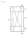
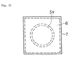
- Figs. 10 and 11 are a side view and a plan view illustrating a bead inductor having metallic caps mounted thereon.
- One end 5a of the conductor coil 5 is electrically connected to a metallic cap 7, while the other end 5b of the conductor coil 5 is electrically connected to a metallic cap 8.
- the metallic caps 7 and 8 are used as external terminal electrodes.
- the spacer pin is removed after formation of the outer portion located outside of the conductor coil via molding.
- To remove the spacer pin it is necessary to open the mold and to cut the protruding portion at the top portion of the molded body. This makes it difficult to automate and simplify the injection molding cycle. Therefore, when the conventional bead inductor production method is used, molded bodies cannot be formed with high productivity.
- preferred embodiments of the present invention provide a method of manufacturing a bead inductor and a bead inductor molded body producing apparatus, which achieve improved and highly efficient production of bead inductor molded bodies having a conductor coil embedded therein.
- a method of producing a bead inductor in which a molded body having a hollow core conductor coil embedded in rubber or resin material containing magnetic powder is formed, and in which both ends of the conductor coil in the molded body are exposed to electrically connect external terminal electrodes to both of the exposed ends of the conductor coil, the method including the steps of forming an outer portion outside of the conductor coil via molding, by disposing the conductor coil in a cavity of a mold having a first gate and a second gate formed therein, disposing a spacer pin which passes through the core of the conductor coil and extends up to the second gate to close the second gate, and supplying the rubber or the resin material containing magnetic powder into the mold cavity from the first gate and forming the molded body with the conductor coil embedded therein, by, after the formation of the outer portion outside of the conductor coil, closing the first gate, pulling the spacer pin out of the mold cavity, and supplying from the second gate the rubber
- the spacer pin is pulled out.
- the spacer pin is disposed so as to pass through the core of the conductor coil and to extend up to the second gate to close the second gate.
- the spacer pin is pulled out, a space which extends through the core of the conductor coil from the second gate is formed. From the second gate, resin or rubber material is supplied into the space located inside of the conductor coil.
- the outer portion does not have to be removed after the formation of the outer portion outside of the conductor coil, so that the next step of forming an inner portion inside of the conductor coil can be carried out with the outer portion being disposed in the mold cavity.
- the mold may have an accommodating hole for accommodating the spacer pin therein.
- a portion of the spacer pin may be pushed out of the accommodating hole and pushed into the mold cavity.
- the spacer pin may be pulled out so that a portion of the spacer pin is accommodated in the accommodating hole.
- the mold may include an upper mold portion and a lower mold portion.
- the mold may include an upper mold portion and a lower mold portion, it possible to stably and easily insert the conductor coil into the mold.
- the spacer pin may be divided into a first spacer pin portion and a second spacer pin portion, the first spacer pin portion having a shape which fits into the accommodating hole formed in the lower mold portion, and the second spacer pin portion having a shape which fits into the second gate formed in the upper mold portion.
- a portion of the first spacer pin portion and a portion of the second spacer pin portion of the spacer pin may be pushed into the mold cavity from the accommodating hole and from the second gate, respectively, in order to bring the first spacer pin portion and the second spacer pin portion into contact with each other, whereby the spacer pin is formed so as to pass through the mold cavity.
- the first spacer pin portion may be pulled out so that a portion thereof is accommodated in the accommodating hole formed in the lower mold portion, and the second spacer pin portion may be pulled out and removed out of the mold from the second gate.
- the spacer pin may be divided into a first spacer pin portion and a second spacer pin portion and formed so as to pass through the mold cavity.
- a spacer pin may be formed by pushing a portion of the first spacer pin portion and a portion of the second spacer pin portion into the mold cavity and causing the first and second spacer pin portions to contact each other.
- the first gate may be formed in the upper mold portion.
- the first gate may be formed in the upper mold portion, it is much easier to design, for example, a molding machine or a mold.
- the spacer pin is divided into a first spacer pin portion and a second spacer pin portion and formed so as to pass through the mold cavity, or in the case where the first gate is formed in the upper mold portion, when the conductor coil is disposed in the mold cavity, a portion of the first spacer pin portion may be pushed out of the accommodating hole, and the core of the conductor coil may be mounted onto the first spacer pin portion in order to position the conductor coil in the cavity.
- the conductor coil may be positioned by inserting the core of the conductor coil onto the first spacer pin portion, it is much easier to design a molding machine.
- the first gate may be closed by inserting a closing pin into the first gate.
- the first gate may be closed by inserting a closing pin into the first gate, the structure of, for example, a molding machine or a mold is greatly simplified.
- the molded body When the first gate is closed by inserting a closing pin, after the formation of the inner portion inside of the conductor coil via molding, the molded body may be ejected from the mold by pushing a portion of the closing pin out of the first gate and inserting the portion of the closing pin into the mold cavity.
- the molded body may be ejected from the mold via the closing pin used to close the first gate, the structure of, for example, a molding machine or a mold can be greatly simplified, and the molded body can be automatically ejected after molding.
- the second spacer pin portion which is removed out of the mold may be used as the closing pin for insertion into the first gate.
- the second spacer pin portion may be used as the closing pin, the structure of, for example, a molding machine or a mold can be greatly simplified.
- a molding cycle including the steps of inserting the conductor coil into the mold cavity, forming the outer portion outside of the conductor coil via molding, forming the inner portion inside of the conductor coil via molding, and ejecting the molded body from the mold may be repeated by automatic control.
- an apparatus for producing a molded body to be included in a bead inductor in which the molded body is formed in a mold cavity via injection molding when producing the bead inductor by electrically connecting external terminal electrodes to both ends of a hollow core conductor coil disposed in the molded body formed by embedding the hollow core conductor coil in rubber or resin material containing magnetic powder
- the apparatus including an upper mold portion having a first gate and a second gate arranged to allow rubber or the resin material containing magnetic powder to be supplied into the mold cavity, a lower mold portion which is fitted to the upper mold portion to define the mold cavity, the lower mold portion having an accommodating hole in a portion thereof located at a position in correspondence with a substantially center portion of the mold cavity, a first spacer pin portion arranged to be movably disposed in the accommodating hole in the lower mold portion, a second spacer pin portion arranged to be movably disposed in the second gate in the upper mold portion, and a closing pin
- the rubber or the resin material containing magnetic powder is supplied into the cavity from the first gate to form an outer portion outside of the conductor coil the molding.
- the first spacer pin portion is pulled out so that a portion thereof is accommodated in the accommodating hole formed in the lower mold portion, and the second spacer pin portion is pulled out and removed out of the mold from the second gate.
- a closing pin is inserted into the first gate to close the first gate.
- the rubber or the resin material containing magnetic powder is supplied into a space formed inside of the conductor coil, by pulling out the first spacer pin portion and the second spacer pin portion, whereby the molded body having the conductor coil embedded therein is formed.
- an inner portion can be formed inside of the conductor coil, without taking out the outer portion from the mold. This makes it possible to produce molded bodies efficiently and easily.
- the closing pin may be used as the second spacer pin portion.
- the structure of, for example, an injection mold or a mold can be greatly simplified. This makes it possible to automate the molding process and to reduce molding costs.
- the apparatus according to preferred embodiments of the present invention when used or when the closing pin is used as the second spacer pin portion, after the formation of the molded body with the conductor coil embedded therein, the upper mold portion and the lower mold portion which have been fitted together may be separated from each other, and the closing pin may be moved downward to push out and eject the molded body from the cavity.
- the molded body since the molded body may be pushed out of and ejected from the cavity by moving the closing pin downward, the molded body can be easily taken out, and the molding process can be automated.
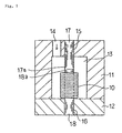
- Fig. 1 is a sectional view of a mold of an apparatus for producing a molded body to be included in a bead inductor, according to a preferred embodiment of the present invention.
- This mold is used to form a molded body via injection molding.
- the mold preferably includes an upper mold portion 11 and a lower mold portion 12. As shown in Fig. 1, when the upper mold portion 11 and the lower mold portion 12 are fitted together, a cavity 13 is formed. A molded body will be formed in the cavity 13 as described below.
- a first gate 14 and a second gate 15 are provided at the upper mold portion 11.
- the first gate 14 and the second gate 15 are arranged to allow rubber or molten resin containing magnetic powder to flow into the cavity 13.
- An accommodating hole 16 is formed in a portion of the lower mold portion 12 located so as to correspond to a location of the approximate center portion of the cavity 13.
- a first spacer pin portion 18 is movably disposed in the accommodating hole 16.
- a second spacer pin portion 17 is movably disposed in the second gate 15 formed in the upper mold portion 11.
- first spacer pin portion 18 and the second spacer pin portion 17 are both pushed into the cavity 13 so that an end portion 18a of the first spacer pin portion 18 and an end portion 17a of the second spacer pin portion 17 contact each other.
- a closing pin (described later) can be movably disposed in the first gate 14. In the state shown in Fig. 1, the closing pin is disposed outside the mold.
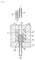
- a conductor coil 10 is inserted onto the first spacer pin portion 18.
- the coil 10 is preferably formed as an hollow core conductor coil by, for example, winding in a spiral or other configuration, a metallic wire (such as a copper wire) coated with an insulating material (such as polyester resin).
- the mold is in an open state, with the upper mold portion 11 being located separate from and above the lower mold portion 12, and the lower mold portion 12 being disposed below the upper mold portion 11.
- a portion of the first spacer pin portion 18 is pushed upward from the through hole 16 in the lower mold portion 12.
- the conductor coil 10 is disposed in the mold by inserting the hollow core of the conductor coil 10 onto the first spacer pin portion 18, so that the conductor coil 10 is fitted onto the first spacer pin portion 18.
- the conductor coil 10 is positioned in the cavity 13 by inserting the conductor coil 10 onto the first spacer pin portion 18.
- the first gate 14 formed in the upper mold portion 11 is in an open state.
- the second spacer pin portion 17 is inserted into the second gate 15 so that the end portion 17a of the second spacer pin portion 17 is pushed downward and protrudes from the second gate 15.
- the upper mold portion 11 is moved downward relative to the lower mold portion 12 in order to fit the upper and lower mold portions 11, 12 together, as shown in Fig. 1.
- the end portion 18a of the first spacer pin portion 18 and the end portion 17a of the second spacer pin portion 17 are brought into contact with each other in the cavity 13, whereby a spacer pin which passes through the cavity 13 in the vertical direction so as to pass through the hollow core of the coil 10 is formed.
- the second spacer pin portion 17 does not necessarily have to be moved downward before fitting the upper mold portion 11 and the lower mold portion 12 together.
- the second spacer pin 17 may be moved downward so that the end portion 17a thereof comes into contact with the end portion 18a of the first spacer pin portion 18 after fitting the upper mold portion 11 and the lower mold portion 12 together.
- molten rubber or molten resin containing magnetic powder is injected into the cavity 13 from the first gate 14 to form an outer portion outside of the conductor coil 10 via molding. Since the spacer pin defined by the first spacer pin portion 18 and the second spacer pin portion 17 is disposed in the cavity 13, resin is molded in the area around the spacer pin.
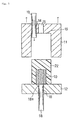
- Fig. 3 illustrates a state after formation of an outer portion outside of the conductor coil 10 using the above-described molding method.
- a molded body 20 is formed outside of the conductor coil 10.
- the first spacer pin portion 18 is moved downward and pulled out of the molded body 20.
- the first spacer pin portion 18 is moved until its top end 18a is level with the top surface of the lower mold portion 12. Then, the first spacer pin portion 18 is fixed at that location.
- the second spacer pin portion 17 is moved upward and pulled out of the molded body 20. Then, the second spacer pin portion 17 is pulled up through the second gate 15 and removed out of the mold. Pulling the first spacer pin portion 18 and the second spacer pin portion 17 out of the molded body 20 causes a space 21 to be formed in the approximate center portion of the molded body 20. The space 21 is formed so as to extend through the core of the conductor coil 10 and so as to lead to the second gate 15. A closing pin 19 is inserted into the first gate 14 in order to close the first gate 14.
- Fig. 4 illustrates the first gate 14 which has been closed as a result of inserting the closing pin 19 into the first gate 14.
- the second gate 15 leads to the space 21 in the approximate center portion of the molded body 20, and the space 21 leads to a portion located inside of the conductor coil 10.
- molten rubber or molten resin material is injected into the space 21 from the second gate 15 so as to form in the space 21 an inner portion inside of the conductor coil 10.
- Fig. 5 is a sectional view illustrating a state after formation of an inner portion inside of the molded body 20, in the space 21, using the above-described method.
- filling the space 21 in the approximate center portion of the molded body 20 results in the formation of a molded body 22 having the conductor coil 10 embedded therein.
- the core of the conductor coil 10 is also filled with resin or rubber material, which is preferably molded.
- the upper mold portion 11 is moved upward relative to the lower mold portion 12 and separated therefrom, whereby the mold is opened, as shown in Fig. 5.
- Molded bodies 22 having the conductor coil 10 embedded therein tend to remain fitted to the upper mold portion 11 in which cavity 13 is formed. In such a case, molded bodies 22 are ejected from the upper mold portion 11 by moving the closing pin 19 in the first gate 14 downward and pushing out the molded bodies 22.
- a molded body 22 with a conductor coil 10 embedded therein is produced.
- the first spacer pin portion 18 is moved upward in order to set the mold in the state shown in Fig. 2. Then, the conductor coil 10 is inserted onto the first spacer pin portion 18 to form the next molded body.
- both ends of the molded body 22 obtained by the above-described method are cut with a dicing saw or similar device so that the ends of the conductor coil are exposed.
- the exposed ends of the conductor coil in the preferred embodiments have external terminal electrodes, such as metallic caps, mounted thereon so as to complete a bead inductor.
- an inner portion can be formed inside of the conductor coil 10 without taking the molded body 20 out of the mold. Therefore, molded bodies used to form bead inductors can be efficiently produced. Since manual operations do not have to be carried out during the molding process, the molding process can be automatically controlled, making it possible to repeat by automatic control the molding process cycle which includes placing the conductor coil into a mold, forming an outer portion outside of the conductor coil via molding, forming an inner portion inside of the conductor coil via molding, and ejecting the molded body. Therefore, molded bodies can be automatically produced, and operation efficiency of the injection mold can be greatly increased, allowing a large number of molded bodies to be produced with high efficiency.
- the first gate 14 can be closed by inserting therein the second spacer pin portion 17 pulled out of the mold from the second gate 15.
- the second spacer pin portion 17, instead of the closing pin 19, can be used as closing pin.
- a method of producing a bead inductor in which after the formation of the outer portion outside of the conductor coil, molded bodies with a conductor coil embedded therein can be produced by forming an inner portion inside of the conductor coil, without taking out the outer portion from the mold. This makes it possible to produce molded bodies used to form bead inductors very efficiently and automatically.
- An accommodating hole may be formed in the mold to allow insertion and removal of the spacer pin into and from the cavity. This makes it possible to provide an improved production method which allows automation of the molding process.
- the mold may include an upper mold portion and a lower mold portion. This makes it possible to stably dispose the conductor coil in the mold.
- the spacer pin may be divided into a first spacer pin portion and a second spacer pin portion and formed so as to pass through the mold cavity.
- the spacer pin is formed by bringing the first spacer pin portion and the second spacer pin portion into contact with each other in the cavity, thereby making it easier to design the upper mold portion and the lower mold portion so that they are, for example, positioned precisely with respect to each other.
- the first gate may be formed in the upper mold portion. This makes it easier to design, for example, a molding machine or a mold.
- the conductor coil may be positioned by inserting the core of the conductor coil onto the first spacer pin portion. This makes it easier to design a molding machine.
- the first gate may be closed by inserting a closing pin into it. This simplifies the structure of, for example, a molding machine or a mold.
- the molded body When the first gate is closed by inserting a closing pin into it, the molded body may be ejected from the mold by using the closing pin used to close the first gate. This simplifies the structure of, for example, a molding machine or a mold, and allows the molded body to be ejected automatically after molding.
- the second spacer pin portion may be used as the closing pin. This simplifies the structure of, for example, a molding machine or a mold.
- a molding process including the steps of inserting the conductor coil into the mold cavity, forming the outer portion outside of the conductor coil via molding, forming the inner portion inside of the conductor coil via molding, and ejecting the molded body from the mold can be repeated by automatic control. This makes it possible to automate the molding process carried out to form a bead inductor molded body, making it possible to increase operation efficiency of the molding machine, and to mass-produce molded bodies economically.
- an apparatus for producing a molded body to be included in a bead inductor in which after the formation of the outer portion outside of the conductor coil via molding, an inner portion can be formed inside of the conductor coil, without taking out the outer portion from the mold. This makes it possible to produce molded bodies efficiently.
- the closing pin may be used as the second spacer pin portion. Therefore, the structure of, for example, an injection mold or a mold can be simplified. This makes it possible to automate the molding process and to greatly reduce molding costs.
- the molded body may be pushed out of and ejected from the cavity by moving the closing pin downward. This allows the molded body to be easily and automatically ejected.
Landscapes
- Engineering & Computer Science (AREA)
- Power Engineering (AREA)
- Manufacturing & Machinery (AREA)
- Moulds For Moulding Plastics Or The Like (AREA)
- Insulating Of Coils (AREA)
Applications Claiming Priority (2)
| Application Number | Priority Date | Filing Date | Title |
|---|---|---|---|
| JP25110098 | 1998-09-04 | ||
| JP25110098A JP3318654B2 (ja) | 1998-09-04 | 1998-09-04 | ビーズインダクタの製造方法及び製造装置 |
Publications (2)
| Publication Number | Publication Date |
|---|---|
| EP0984465A2 true EP0984465A2 (de) | 2000-03-08 |
| EP0984465A3 EP0984465A3 (de) | 2000-03-22 |
Family
ID=17217653
Family Applications (1)
| Application Number | Title | Priority Date | Filing Date |
|---|---|---|---|
| EP99117262A Withdrawn EP0984465A3 (de) | 1998-09-04 | 1999-09-02 | Herstellungsverfahren eines Induktors und Vorrichtung zu seiner Herstellung |
Country Status (4)
| Country | Link |
|---|---|
| US (2) | US6375884B1 (de) |
| EP (1) | EP0984465A3 (de) |
| JP (1) | JP3318654B2 (de) |
| SG (1) | SG89293A1 (de) |
Cited By (2)
| Publication number | Priority date | Publication date | Assignee | Title |
|---|---|---|---|---|
| GB2360394A (en) * | 2000-03-14 | 2001-09-19 | Murata Manufacturing Co | Inductor chip and its method of manufacture providing exposed projecting coil ends for connection to external electrodes |
| EP1282143A3 (de) * | 2001-08-01 | 2003-04-02 | Kitagawa Industries Co., Ltd. | Herstellungsverfahren eines Magnetkörpers, Magnetkörper und Leiterplatte |
Families Citing this family (14)
| Publication number | Priority date | Publication date | Assignee | Title |
|---|---|---|---|---|
| US6793863B1 (en) * | 1999-06-15 | 2004-09-21 | Lexington Insulators | Process for producing a spark plug boot resistor assembly |
| US6943392B2 (en) * | 1999-08-30 | 2005-09-13 | Micron Technology, Inc. | Capacitors having a capacitor dielectric layer comprising a metal oxide having multiple different metals bonded with oxygen |
| DE10023208A1 (de) * | 2000-05-12 | 2001-11-15 | Alstom Power Nv | Isolierung von Statorwicklungen im Spritzgussverfahren |
| US7015783B2 (en) * | 2001-02-27 | 2006-03-21 | Matsushita Electric Industrial Co., Ltd. | Coil component and method of manufacturing the same |
| US20070159753A1 (en) * | 2006-01-09 | 2007-07-12 | Randall Michael S | System for EMI/RFI filtering and transient voltage suppression |
| JP5256010B2 (ja) * | 2008-12-19 | 2013-08-07 | 東光株式会社 | モールドコイルの製造方法 |
| JP5329202B2 (ja) * | 2008-12-19 | 2013-10-30 | 東光株式会社 | モールドコイルの製造方法 |
| JP5534551B2 (ja) * | 2009-05-07 | 2014-07-02 | 住友電気工業株式会社 | リアクトル |
| JP5255577B2 (ja) * | 2010-01-13 | 2013-08-07 | 古河電気工業株式会社 | 基板および基板の製造方法 |
| EP2551864A4 (de) * | 2010-03-20 | 2014-11-05 | Daido Steel Co Ltd | Verfahren zur herstellung eines eingekapselten spulenkörpers und eingekapselter spulenkörper |
| US9947465B2 (en) * | 2014-06-23 | 2018-04-17 | Mag. Layers Scientific-Technics Co., Ltd. | Magnetic assembly packaging process |
| JP6447405B2 (ja) * | 2015-08-04 | 2019-01-09 | 株式会社村田製作所 | 可変インダクタ |
| JP6477429B2 (ja) * | 2015-11-09 | 2019-03-06 | 株式会社村田製作所 | コイル部品 |
| CN112103029B (zh) * | 2020-09-16 | 2022-03-11 | 横店集团东磁股份有限公司 | 一种电感器及其制作方法 |
Family Cites Families (26)
| Publication number | Priority date | Publication date | Assignee | Title |
|---|---|---|---|---|
| US1284553A (en) * | 1918-05-17 | 1918-11-12 | Vincent G Apple | Mold. |
| US1864331A (en) * | 1929-11-30 | 1932-06-21 | Gen Electric | Electrical coil |
| US2018480A (en) * | 1932-05-04 | 1935-10-22 | Herbert F Apple | Mold for dynamo machine elements |
| CH374767A (fr) * | 1961-11-20 | 1964-01-31 | Lucifer Sa | Procédé pour noyer une bobine de fil électrique dans une masse de matière synthétique thermoplastique et bobine noyée obtenue par ce procédé |
| US3293694A (en) * | 1962-03-05 | 1966-12-27 | Dayton Prec Corp | Mold apparatus for making subflush commutators |
| US3254372A (en) * | 1962-06-19 | 1966-06-07 | Bendix Corp | Apparatus for fabricating and insulating lamination assemblies of a stator or rotor unit for use in an electrical device |
| US3268845A (en) * | 1965-09-21 | 1966-08-23 | Henry B Whitmore | Respiration and movement transducer |
| US3543349A (en) * | 1967-03-10 | 1970-12-01 | Drymit Sa | Mould for use in an injection moulding process |
| US3809733A (en) * | 1968-11-06 | 1974-05-07 | Ici Ltd | Production of double layer laminates |
| US3584345A (en) * | 1968-12-09 | 1971-06-15 | Keith P Beastrom | Die casting apparatus |
| US4025269A (en) * | 1976-02-09 | 1977-05-24 | Acro Products, Inc. | Mold structure and cavity forming insert arrangement therefor |
| US4075273A (en) * | 1976-04-14 | 1978-02-21 | Liautaud James P | Method of making a coil form by injection molding |
| US4193185A (en) * | 1978-01-12 | 1980-03-18 | Liautaud James P | Method of making a high tolerance coil assembly |
| JPS6048893B2 (ja) * | 1978-07-25 | 1985-10-30 | 八十太郎 塚田 | 密封電気コイルの製造法およびその型 |
| US4385025A (en) * | 1979-10-22 | 1983-05-24 | Barry Wright Corporation | Method of coinjection molding of thermoplastic and thermoplastic elastomer |
| JPS5834988A (ja) | 1981-08-25 | 1983-03-01 | Nec Corp | 半導体レ−ザの製造方法 |
| JPS5834908A (ja) | 1981-08-26 | 1983-03-01 | Toshiba Corp | モ−ルドコイルの製造方法 |
| JPS59144109A (ja) | 1983-02-07 | 1984-08-18 | Hitachi Metals Ltd | インダクタンス導線部品 |
| DE3334827A1 (de) | 1983-09-27 | 1985-04-11 | Vogt Gmbh & Co Kg, 8391 Erlau | Stoerschutzdrossel und verfahren zur herstellung solcher stoerschutzdrosseln |
| US4725395A (en) * | 1985-01-07 | 1988-02-16 | Motorola, Inc. | Antenna and method of manufacturing an antenna |
| CA1307330C (en) * | 1988-09-20 | 1992-09-08 | Sanyo Electric Co., Ltd. | High voltage through type capacitor and manufacturing method therefor |
| JPH02249217A (ja) | 1989-03-22 | 1990-10-05 | Sony Corp | 磁性樹脂モールドコイルの製造方法 |
| US5589129A (en) * | 1993-02-19 | 1996-12-31 | Kabushiki Kaisha Toshiba | Method of manufacturing a molding using a filler or an additive concentrated on an arbitrary portion or distributed at a gradient concentration |
| FR2723248B1 (fr) * | 1994-07-29 | 1996-09-20 | Seb Sa | Procede de realisation d'un inducteur |
| US6198373B1 (en) * | 1997-08-19 | 2001-03-06 | Taiyo Yuden Co., Ltd. | Wire wound electronic component |
| JP3301384B2 (ja) * | 1998-06-23 | 2002-07-15 | 株式会社村田製作所 | ビーズインダクタの製造方法及びビーズインダクタ |
-
1998
- 1998-09-04 JP JP25110098A patent/JP3318654B2/ja not_active Expired - Lifetime
-
1999
- 1999-09-02 SG SG9904285A patent/SG89293A1/en unknown
- 1999-09-02 US US09/388,797 patent/US6375884B1/en not_active Expired - Fee Related
- 1999-09-02 EP EP99117262A patent/EP0984465A3/de not_active Withdrawn
-
2002
- 2002-02-06 US US10/066,718 patent/US6702562B2/en not_active Expired - Fee Related
Cited By (5)
| Publication number | Priority date | Publication date | Assignee | Title |
|---|---|---|---|---|
| GB2360394A (en) * | 2000-03-14 | 2001-09-19 | Murata Manufacturing Co | Inductor chip and its method of manufacture providing exposed projecting coil ends for connection to external electrodes |
| GB2360394B (en) * | 2000-03-14 | 2002-09-11 | Murata Manufacturing Co | Method for manufacturing inductor |
| US6614338B2 (en) | 2000-03-14 | 2003-09-02 | Murata Manufacturing Co., Ltd. | Inductor and method for manufacturing same |
| EP1282143A3 (de) * | 2001-08-01 | 2003-04-02 | Kitagawa Industries Co., Ltd. | Herstellungsverfahren eines Magnetkörpers, Magnetkörper und Leiterplatte |
| US6758999B2 (en) | 2001-08-01 | 2004-07-06 | Kitagawa Industries Co., Ltd. | Forming method of magnetic body and printed circuit board |
Also Published As
| Publication number | Publication date |
|---|---|
| SG89293A1 (en) | 2002-06-18 |
| EP0984465A3 (de) | 2000-03-22 |
| JP2000082629A (ja) | 2000-03-21 |
| JP3318654B2 (ja) | 2002-08-26 |
| US6375884B1 (en) | 2002-04-23 |
| US20020102319A1 (en) | 2002-08-01 |
| US6702562B2 (en) | 2004-03-09 |
Similar Documents
| Publication | Publication Date | Title |
|---|---|---|
| US6375884B1 (en) | Method of manufacturing bead inductor | |
| US5341149A (en) | Antenna rod and procedure for manufacturing same | |
| CA2273769C (en) | Method of producing inductor | |
| JP6890260B2 (ja) | インダクタ部品およびその製造方法 | |
| CA1043974A (en) | Method for encapsulating electrical components and the mould used for the method | |
| JP2002083732A (ja) | インダクタ及びその製造方法 | |
| US20100134233A1 (en) | Inductor and method for making the same | |
| US6590487B2 (en) | Moulded coil and production method thereof | |
| US6189204B1 (en) | Method of manufacturing a bead inductor | |
| KR20020090856A (ko) | 인덕터 및 그 제조방법 | |
| CN1006745B (zh) | 小型电感器及其制造方法 | |
| CN114023548A (zh) | 一种电感磁性元件制作方法及电感磁性元件 | |
| JPH05315176A (ja) | コイル装置の製造方法 | |
| KR100367769B1 (ko) | 비드 인덕터 및 그 제조 방법 | |
| CN102034589A (zh) | 电感元件与电感元件的制造方法 | |
| GB2034128A (en) | Flyback transformers and methods of manufacture thereof | |
| US4112576A (en) | Method of making a switch | |
| KR100812974B1 (ko) | 코아일체형 보빈제작용 금형 및 보빈제조방법 | |
| EP4362050B1 (de) | Wasserdichte elektromagnetische vorrichtung und herstellungsverfahren dafür | |
| KR910004803B1 (ko) | 리드선과 일체로 되는 콘넥터 제조방법 | |
| KR100387082B1 (ko) | 매립형 절연변압기 및 제조방법 | |
| KR200222264Y1 (ko) | 칩형 인덕터 | |
| JPH09266122A (ja) | フェライト製キャップ状コアの成形方法 | |
| JPS5846945B2 (ja) | カップ形電機子の製造方法 | |
| JPS59222915A (ja) | モ−ルドコイルの製造方法 |
Legal Events
| Date | Code | Title | Description |
|---|---|---|---|
| PUAI | Public reference made under article 153(3) epc to a published international application that has entered the european phase |
Free format text: ORIGINAL CODE: 0009012 |
|
| PUAL | Search report despatched |
Free format text: ORIGINAL CODE: 0009013 |
|
| 17P | Request for examination filed |
Effective date: 19990902 |
|
| AK | Designated contracting states |
Kind code of ref document: A2 Designated state(s): DE FR GB |
|
| AX | Request for extension of the european patent |
Free format text: AL;LT;LV;MK;RO;SI |
|
| AK | Designated contracting states |
Kind code of ref document: A3 Designated state(s): AT BE CH CY DE DK ES FI FR GB GR IE IT LI LU MC NL PT SE |
|
| AX | Request for extension of the european patent |
Free format text: AL;LT;LV;MK;RO;SI |
|
| AKX | Designation fees paid |
Free format text: DE FR GB |
|
| 17Q | First examination report despatched |
Effective date: 20021017 |
|
| GRAH | Despatch of communication of intention to grant a patent |
Free format text: ORIGINAL CODE: EPIDOS IGRA |
|
| STAA | Information on the status of an ep patent application or granted ep patent |
Free format text: STATUS: THE APPLICATION HAS BEEN WITHDRAWN |
|
| 18W | Application withdrawn |
Effective date: 20030626 |