EP0984522B1 - Elektrischer Verbinder mit Lagesicherungsvorrichtung - Google Patents
Elektrischer Verbinder mit Lagesicherungsvorrichtung Download PDFInfo
- Publication number
- EP0984522B1 EP0984522B1 EP99117010A EP99117010A EP0984522B1 EP 0984522 B1 EP0984522 B1 EP 0984522B1 EP 99117010 A EP99117010 A EP 99117010A EP 99117010 A EP99117010 A EP 99117010A EP 0984522 B1 EP0984522 B1 EP 0984522B1
- Authority
- EP
- European Patent Office
- Prior art keywords
- connector
- locking arm
- cpa
- cpa device
- stop
- Prior art date
- Legal status (The legal status is an assumption and is not a legal conclusion. Google has not performed a legal analysis and makes no representation as to the accuracy of the status listed.)
- Expired - Lifetime
Links
- 230000000903 blocking effect Effects 0.000 claims description 11
- 230000013011 mating Effects 0.000 claims description 9
- 230000036316 preload Effects 0.000 description 12
- 125000006850 spacer group Chemical group 0.000 description 7
- 230000007246 mechanism Effects 0.000 description 4
- 230000000295 complement effect Effects 0.000 description 2
- 239000000463 material Substances 0.000 description 2
- 230000003213 activating effect Effects 0.000 description 1
- 230000001419 dependent effect Effects 0.000 description 1
- 239000003989 dielectric material Substances 0.000 description 1
Images


Classifications
-
- H—ELECTRICITY
- H01—ELECTRIC ELEMENTS
- H01R—ELECTRICALLY-CONDUCTIVE CONNECTIONS; STRUCTURAL ASSOCIATIONS OF A PLURALITY OF MUTUALLY-INSULATED ELECTRICAL CONNECTING ELEMENTS; COUPLING DEVICES; CURRENT COLLECTORS
- H01R11/00—Individual connecting elements providing two or more spaced connecting locations for conductive members which are, or may be, thereby interconnected, e.g. end pieces for wires or cables supported by the wire or cable and having means for facilitating electrical connection to some other wire, terminal, or conductive member, blocks of binding posts
-
- H—ELECTRICITY
- H01—ELECTRIC ELEMENTS
- H01R—ELECTRICALLY-CONDUCTIVE CONNECTIONS; STRUCTURAL ASSOCIATIONS OF A PLURALITY OF MUTUALLY-INSULATED ELECTRICAL CONNECTING ELEMENTS; COUPLING DEVICES; CURRENT COLLECTORS
- H01R13/00—Details of coupling devices of the kinds covered by groups H01R12/70 or H01R24/00 - H01R33/00
- H01R13/62—Means for facilitating engagement or disengagement of coupling parts or for holding them in engagement
- H01R13/639—Additional means for holding or locking coupling parts together, after engagement, e.g. separate keylock, retainer strap
-
- H—ELECTRICITY
- H01—ELECTRIC ELEMENTS
- H01R—ELECTRICALLY-CONDUCTIVE CONNECTIONS; STRUCTURAL ASSOCIATIONS OF A PLURALITY OF MUTUALLY-INSULATED ELECTRICAL CONNECTING ELEMENTS; COUPLING DEVICES; CURRENT COLLECTORS
- H01R13/00—Details of coupling devices of the kinds covered by groups H01R12/70 or H01R24/00 - H01R33/00
- H01R13/62—Means for facilitating engagement or disengagement of coupling parts or for holding them in engagement
- H01R13/627—Snap or like fastening
- H01R13/6271—Latching means integral with the housing
- H01R13/6273—Latching means integral with the housing comprising two latching arms
-
- H—ELECTRICITY
- H01—ELECTRIC ELEMENTS
- H01R—ELECTRICALLY-CONDUCTIVE CONNECTIONS; STRUCTURAL ASSOCIATIONS OF A PLURALITY OF MUTUALLY-INSULATED ELECTRICAL CONNECTING ELEMENTS; COUPLING DEVICES; CURRENT COLLECTORS
- H01R13/00—Details of coupling devices of the kinds covered by groups H01R12/70 or H01R24/00 - H01R33/00
- H01R13/64—Means for preventing incorrect coupling
- H01R13/641—Means for preventing incorrect coupling by indicating incorrect coupling; by indicating correct or full engagement
-
- H—ELECTRICITY
- H01—ELECTRIC ELEMENTS
- H01R—ELECTRICALLY-CONDUCTIVE CONNECTIONS; STRUCTURAL ASSOCIATIONS OF A PLURALITY OF MUTUALLY-INSULATED ELECTRICAL CONNECTING ELEMENTS; COUPLING DEVICES; CURRENT COLLECTORS
- H01R13/00—Details of coupling devices of the kinds covered by groups H01R12/70 or H01R24/00 - H01R33/00
- H01R13/40—Securing contact members in or to a base or case; Insulating of contact members
- H01R13/42—Securing in a demountable manner
- H01R13/436—Securing a plurality of contact members by one locking piece or operation
- H01R13/4367—Insertion of locking piece from the rear
- H01R13/4368—Insertion of locking piece from the rear comprising a temporary and a final locking position
Definitions
- This invention generally relates to the art of electrical connectors and, particularly, to a connector position assurance system for an electrical connector adapted to mate with another mateable connecting device.
- latching systems have been used with electrical connectors to provide such secure engagement. Such systems usually provide this secure engagement with ease of attachment and detachment. For instance, latching mechanisms have been developed which include pivotally supported latch arms that interlock with each other or that interlock with a complementary latching mechanism of the mateable connector or connecting device.
- connector position assurance devices also are known in the art. Typically, the primary function of such devices is to verify that the connectors are fully mated and latched, i.e. that the latching mechanisms are fully or securely engaged. A secondary function often is to prevent the latching mechanisms from inadvertently unlatching and permitting the connectors to separate.
- These connector position assurance functions may be accomplished in a variety of ways, but most prior art connector position assurance systems employ a spacer that cannot be inserted into its intended position unless the latching arm is fully engaged, and the latching arm cannot be moved when the spacer is properly positioned. Problems often are encountered with such removable spacers because they may be lost or misplaced. Therefore, in some position assurance systems, the spacers may be preloaded on the connector housing. However, one of the problems with such systems is that, should the preloaded spacer be inadvertently moved to its final locking position before the connectors are mated, mating cannot take place.
- US- PS 5,330,369 discloses a connector which comprises a pair of connector housings, wherein the connector housings are locked and connected by means of locking members.
- a detecting spacer locked and connected to one of the pair of connector housings serves to indicate a properly locked connector.
- the detecting spacer is constructed to be withdrawn when the connector housings are properly coupled with each other.
- US- PS 5,681,178 discloses an electrical connector assembly having a mateable plughousing and receptacle housing as well as a connector position assurance device for indicating that mateable connector housings have been fully mated together.
- the connector position assurance device CPA includes a central beam having a central detent thereon with an end section for engaging a front section of the plughousing when the connector position assurance device is in a fully advanced position.
- the connector position assurance device can be latched to the plughousing in a pre-engagement position for preventing inadvertent withdrawal of the CPA from a plughousing.
- EP-A-0840398 discloses a connector with a pair of havings and a CPA.
- a locking arm is set on a fulerum to rotate for latching with a mating housing portion.
- the CPA is slidable along the locking arm, and movable towards its bloching position when a wedge of the mating housing releases the CPA from a stop edge. To ride over the whole step, the CPA is lifted over it.
- the present invention is directed to solving these problems and satisfying a need for an improved connector position assurance system.
- An object, therefore, of the invention is to provide a new and improved connector position assurance system for an electrical connector adapted to mate with another mateable connecting device.
- an electrical connector in the exemplary embodiment of the invention, includes a housing having a guideway and at least one stop surface near the guideway.
- a primary flexible locking arm is pivoted on the housing and includes a latch for mechanically interlocking with a cooperating latch of the mateable connecting device.
- a connector position assurance (CPA) device is slidably mounted on the housing for movement along the guideway between a first position allowing movement of the locking arm and mating of the connector with the mateable connecting device and a second position blocking movement of the locking arm away from a latched position.
- the CPA device includes a flexible stop arm engageable with the stop surface on the housing to prevent the CPA device from moving from its first to its second position.
- the mateable connecting device includes an actuator for moving the flexible stop arm of the CPA device out of engagement with the stop surface automatically when the connector is fully mated with the connecting device. Thereby, the CPA device is allowed to move from its first position to its second position indicating full mating of the connector.
- the primary flexible locking arm is pivoted to the housing on a fulcrum between a latch end and a rear end of the locking arm.
- the guideaway comprises a pair of guide rails between which the CPA device slides, each guide rail including one of the stop surfaces.
- the CPA device is generally E-shaped to include a pair of outside legs and a center leg.
- the outside legs comprise a pair of the flexible stop arms engageable with the two stop surfaces of the pair of guide rails.
- the mateable connecting device includes a pair of actuators for moving the stop arms out of engagement with the stop surfaces.
- the center leg of the E-shaped CPA device extends from a blocking surface which is movable beneath the rear end of the primary locking arm when the CPA device is in its second position to prevent flexing of the front latch end of the locking arm.
- the center leg of the E-shaped CPA device includes detents engageable with the rear end of the primary locking arm to define the first and second positions of the CPA device.
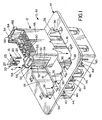
- an electrical connector assembly generally designated 10 which includes an electrical connector, generally designated 12, adapted for mating with another mateable connecting device, generally designated 14.
- a connector position assurance (CPA) device generally designated 16 is mounted on each opposite side of connector 12 in the direction of arrow "A". Only one of the CPA devices is shown in the drawings.
- Mateable connecting device 14 is a mateable connecting receptacle structure having a plurality (three) of receptacles 18. Although only one connector 12 is shown in the drawings, one of the connectors is inserted into each receptacle 18 in the direction of arrow "B".
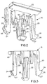
- FIGS 2 and 3 show CPA device 16.
- the device is generally E-shaped to define a pair of outside legs 20 and a center leg 22 joined by a cross portion 23 which defines an enlarged flange for grasping by a user to manually manipulate and move the CPA device.
- Each outside leg 20 includes an outwardly directed latch hook 24 having a forwardly facing angled or chamfered surface 26.
- the outside legs have blunt distal ends 27.
- Center leg 22 extends from a central blocking surface 25 and includes a latch hook 28 with an angled or chamfered surface 30, along with a raised boss 32 having chamfered surfaces 34 on opposite sides thereof.
- latch hook 28 and raised boss 32 form detents which define respective positions of the CPA device on connector 12.
- mateable connecting device 14 has a pair of actuator posts 36 at opposite sides of a recessed area 38 at each opposite end of each receptacle 18.
- the connecting device may be a one-piece structure unitarily molded of plastic material or the like.
- a cut-out wall 40 is located at each opposite end of each receptacle 18 so as to be somewhat flexible in relation to a more rigid side wall 42 of the connecting device.
- a cooperating latch 44 having a lead-in chamfered surface 46, projects outwardly from each flexible wall 40.
- latches 44 are provided for cooperating with latches on primary locking arms of connectors 12, and actuator posts 36 are provided for activating CPA device 16 so that the CPA device can move to its blocking position.
- connector 12 includes a housing 48 of dielectric material for mounting a plurality of terminals (not shown) in respective terminal-receiving cavities or passages 50.
- the housing may be molded of plastic material or the like.
- the housing has a guideway defined by a pair of laterally spaced guide rails 52 and a mouth 54 defined by a pair of laterally spaced guide rail flanges 56.
- a primary flexible locking arm 58 is pivotally mounted on a fulcrum 60 between or intermediate a front latch end 62 of the locking arm and a rear end 64 of the locking arm.
- a closed slot 66 extends between the opposite ends of the locking arm to define a front latch shoulder 68 and a rear positioning shoulder 70.
- Each guide rail 52 has an aperture 72 defining a stop surface 74.
- CPA device 16 is shown removed from connector 12, but the CPA device is mountable on its respective end of the connector housing 48 in the direction of arrows "A" until the CPA device is in its first or pre-load position shown in Figures 6 and 7.
- CPA device 16 has been moved through mouth 54 and slidably between guide rail flanges 56 and guide rails 52.
- Outside legs 20 (Figs. 2 and 3) of the CPA device define flexible stop arms thereof.
- chamfered leading surfaces 26 of latch hooks 24 engage the inside corners of guide rail flanges 56 to flex stop arms 20 inwardly until the latch hooks become aligned with apertures 72 in guide rails 58.
- the stop arms snap back outwardly as latch hooks 24 snap into apertures 72. This defines the pre-load position of CPA device 16.
- the CPA device In the pre-load position, the CPA device cannot back out of mouth 54 because of the interengagement of latch hooks 24 with the bottom ends 56a of guide rail flanges 56 as clearly shown in Figure 7.
- abrupt distal ends 27 (Figs. 2 and 3) of flexible stop arms 20 engage stop surfaces 74 defined by apertures 72. This prevents the CPA device from being moved inwardly beyond its pre-load position. In other words, when latch hooks 24 snap into apertures 72 in guide rails 52, the CPA device cannot move either in or out of its pre-load position.
- rear end 64 of primary locking arm 58 is disposed between latch hook 28 and raised boss 32 of center leg 22 of the CPA device. This allows free pivoting movement of primary locking arm 52 about fulcrum 60. In other words, either opposite end 62 or 64 of the primary locking arm can "teeter” about fulcrum 60 when the CPA device is in its pre-load position.
- Figure 8 shows connector 12 and CPA device 16 being moved further into its respective receptacle 18 (Fig. 1) of mateable connecting device 14 in the direction of arrow "B".
- FIG. 1 shows connector 12 and CPA device 16 being moved further into its respective receptacle 18 (Fig. 1) of mateable connecting device 14 in the direction of arrow "B”.
- front latch end 62 of primary locking arm 52 snaps into mechanical interlocking engagement with cooperating latch 44 on the mateable connecting device.
- actuator posts 36 engage chamfered surfaces 26 of latch hooks 24 which project outwardly from stop arms 20 of the CPA device. This causes the stop arms to be biased inwardly in the direction of arrows "D".
- the latch hooks When the latch hooks are biased inwardly, the latch hooks clear apertures 72 (Fig. 7) in guide rails 58, allowing the CPA device to move in the direction of arrow "E" (Fig. 9) to a second position blocking movement of primary locking arm 58 from its latched position.
- the connector can be unmated only by applying a force, in a direction opposite arrow "A" (Fig. 5), to the CPA device at cross portion 23 to push raised boss 32 past rear end 64 and move the CPA device back to its pre-load position.
- a force in a direction opposite arrow "A" (Fig. 5)
- front latch end 62 of primary locking arm 52 can be moved out of interlocking with latch 44 on the mateable connecting device by pushing in on rear end 64 of the locking arm, whereupon the connector can be pulled out of its receptacle 18 in the mateable connecting device.
Landscapes
- Details Of Connecting Devices For Male And Female Coupling (AREA)
Claims (5)
- Verbinder-Lagesicherungssystem für einen elektrischen Verbinder (12), welcher zum Paaren mit einer weiteren verbindbaren Verbindungseinrichtung (14) ausgebildet ist, aufweisend:den Verbinder (12), der ein Gehäuse (48) mit einer Führung (52, 56) und wenigstens einer Anschlagsfläche (74) in der Nähe der Führung enthält;einen primären flexiblen Verriegelungsarm (58) am Gehäuse, der eine Verriegelung (68) zum mechanischen Verriegeln mit einer zusammenwirkenden Verriegelung (44) der verbindbaren Verbindungsvorrichtung (14) enthält; wobei der primäre Verriegelungsarm (58) zu dem Gehäuse (48) um einen Hebeldrehpunkt (60) zwischen einem vorderen Verriegelungsende (62) und einem hinteren Ende (64) des Verriegelungsarms geschwenkt wird,eine Verbinder-Lagesicherungs-(CPA)-Einrichtung (16), die verschiebbar an dem Gehäuse zur Bewegung entlang der Führung (52, 56) zwischen einer ersten Position, die eine Bewegung des Verriegelungsarms (58) und ein Zusammenfügen des Verbinders (12) mit der verbindbaren Verbindungseinrichtung (14) zuläßt, und einer zweiten Position, welche die Bewegung des Verriegelungsarms (58) weg aus einer verriegelten Position verhindert, montiert ist, wobei die CPA-Einrichtung (16) einen flexiblen Anschlagarm (20) enthält, der in die Anschlagsfläche (74) an dem Gehäuse eingreifen kann, um zu verhindern, daß sich die CPA-Einrichtung (16) aus ihrer ersten Position in die zweite Position bewegt, gekennzeichnet durchArretierungen (32, 28) der CPA-Einrichtung (16), die in das hintere Ende (64) des Verriegelungsarms (58) eingreifen können, um die erste und zweite Position der CPA-Einrichtung (16) zu definieren; wobeidie verbindbare Verbindungseinrichtung (14) eine Betätigungseinrichtung (36) enthält, um den flexiblen Anschlagarm (20) der CPA-Einrichtung (16) automatisch aus dem Eingriff mit der Anschlagfläche (74) zu bewegen, wenn der Verbinder vollständig mit der verbindbaren Verbindungseinrichtung zusammengefügt ist, um dadurch die Bewegung der CPA-Einrichtung (16) aus ihrer ersten Position in ihre zweite Position zu ermöglichen, die ein vollständiges Zusammenfügen des Verbinders anzeigt.
- Verbinder-Lagesicherungssystem nach Anspruch 1, wobei der primäre flexible Verriegelunsarm (58) zu dem Gehäuse (48) um einen Hebeldrehpunkt (60) zwischen einem vorderen Verriegelungsende (62) und einem hinteren Ende (64) der Verriegelungsarms geschwenkt wird, und die CPA-Einrichtung (16) einen Blockierungsabschnitt (32) enthält, der unter das hintere Ende (64) des Verriegelungsarms (58) bewegbar ist, wenn sich die CPA-Einrichtung (16) in ihrer zweiten Position befindet, um das Biegen des vorderen Verriegelungsendes (62) des Verriegelungsarms zu verhindern.
- Verbinder-Lagesicherungssystem nach Anspruch 1, wobei die Führung ein Paar von Führungsschienen (52) aufweist, zwischen welchen die CPA-Einrichtung (16) gleitet.
- Verbinder-Lagesicherungssystem nach Anspruch 3, wobei jede Führungsschiene (52) eine der Anschlagflächen (74) enthält, die CPA-Einrichtung (16) ein Paar von flexiblen Anschlagarmen (52) enthält, die in die Anschlagflächen eingreifen können, und die zusammenfügbare Verbindungseinrichtung (14) ein Paar von den Betätigungselementen (36) enthält, um die Anschlagarme (20) aus dem Eingriff mit den Anschlagflächen zu bewegen.
- Verbinder-Lagesicherungssystem nach Anspruch 1, wobei die CPA-Einrichtung (16) einen vergrößerten Flansch (24) zum Erfassen durch einen Benutzer enthält, um eine manuelle Betätigung der CPA-Einrichtung (16) zu erleichtern.
Applications Claiming Priority (2)
| Application Number | Priority Date | Filing Date | Title |
|---|---|---|---|
| US09/145,892 US6045388A (en) | 1998-09-02 | 1998-09-02 | Electrical connector position assurance system |
| US145892 | 1998-09-02 |
Publications (3)
| Publication Number | Publication Date |
|---|---|
| EP0984522A2 EP0984522A2 (de) | 2000-03-08 |
| EP0984522A3 EP0984522A3 (de) | 2000-07-12 |
| EP0984522B1 true EP0984522B1 (de) | 2003-05-14 |
Family
ID=22515007
Family Applications (1)
| Application Number | Title | Priority Date | Filing Date |
|---|---|---|---|
| EP99117010A Expired - Lifetime EP0984522B1 (de) | 1998-09-02 | 1999-08-28 | Elektrischer Verbinder mit Lagesicherungsvorrichtung |
Country Status (5)
| Country | Link |
|---|---|
| US (1) | US6045388A (de) |
| EP (1) | EP0984522B1 (de) |
| JP (1) | JP3131836B2 (de) |
| KR (1) | KR100396977B1 (de) |
| DE (1) | DE69907832T2 (de) |
Families Citing this family (41)
| Publication number | Priority date | Publication date | Assignee | Title |
|---|---|---|---|---|
| US6234826B1 (en) * | 1999-04-30 | 2001-05-22 | Cardell Corporation | Connector position assurance device |
| FR2799889B1 (fr) * | 1999-10-14 | 2006-08-04 | Fci France | Connecteur demontable |
| US6261116B1 (en) * | 1999-11-22 | 2001-07-17 | Yazaki North America, Inc. | Connector position assurance element with lock protection feature |
| GB0011460D0 (en) * | 2000-05-13 | 2000-06-28 | Meritor Light Vehicle Sys Ltd | Method of assembly of first and second component |
| US6514098B2 (en) | 2000-12-28 | 2003-02-04 | Tyco Electronics Corporation | Electrical connector with terminal and connector position assurance devices |
| US7043281B2 (en) * | 2001-08-07 | 2006-05-09 | Darfon Electronics Corp. | Portable electronic apparatus and detachable input device thereof |
| US6884106B2 (en) * | 2002-02-07 | 2005-04-26 | Tyco Electronics Corporation | Electrical connector assembly |
| US6780045B2 (en) * | 2002-03-06 | 2004-08-24 | Tyco Electronics Corporation | Connector position assurance device |
| US6811424B2 (en) * | 2003-03-26 | 2004-11-02 | Fci Americas Technology, Inc. | Electrical connector having connector position assurance member |
| JP4356567B2 (ja) * | 2004-09-09 | 2009-11-04 | 住友電装株式会社 | コネクタ |
| US20060249507A1 (en) * | 2005-04-11 | 2006-11-09 | Watlow Electric Manufacturing Company | Modular controller user interface and method |
| US20060229740A1 (en) * | 2005-04-11 | 2006-10-12 | Watlow Electric Manufacturing Company | Portable user interface assembly and method |
| US7652888B2 (en) * | 2005-04-11 | 2010-01-26 | Watlow Electric Manufacturing Company | Controller housing with connector retention assembly and method |
| US8044329B2 (en) | 2005-04-11 | 2011-10-25 | Watlow Electric Manufacturing Company | Compact limiter and controller assembly and method |
| US7399195B2 (en) * | 2006-12-06 | 2008-07-15 | J.S.T. Corporation | Connector position assurance device and connector assembly incorporating the same |
| US7326074B1 (en) * | 2006-12-06 | 2008-02-05 | J.S.T. Corporation | Connector position assurance device and a connector assembly incorporating the connector position assurance device |
| KR100866090B1 (ko) * | 2007-03-30 | 2008-10-30 | 한국단자공업 주식회사 | 커넥터 어셈블리 |
| US7659732B2 (en) * | 2007-06-15 | 2010-02-09 | Fluke Corporation | Four-wire ohmmeter connector and ohmmeter using same |
| US7780478B2 (en) * | 2007-06-28 | 2010-08-24 | Apple Inc. | Apparatus and methods for connecting two electrical devices together |
| US7470138B1 (en) * | 2007-07-18 | 2008-12-30 | J.S.T. Corporation | Connector position assurance device and connector assembly apparatus incorporating the same |
| GB2486258B (en) * | 2010-12-10 | 2015-02-25 | Paul Foung | Connector locking device |
| JP5751196B2 (ja) * | 2012-03-09 | 2015-07-22 | 住友電装株式会社 | コネクタ |
| US8920187B2 (en) * | 2012-03-09 | 2014-12-30 | Sumitomo Wiring Systems, Ltd. | Connector and connector assembly |
| US8926355B2 (en) * | 2012-06-29 | 2015-01-06 | Lear Corporation | Connector position assurance device for a connector assembly |
| EP3005486B1 (de) * | 2013-06-07 | 2019-09-11 | Amphenol FCI Asia Pte. Ltd. | Elektrischer steckverbinder |
| KR101657362B1 (ko) | 2014-10-29 | 2016-09-13 | 델피 인터내셔널 오퍼레이션즈 룩셈부르크 에스.에이 알.엘. | 커넥터 위치 보장 부재를 갖는 커넥터 조립체 |
| JP2016110851A (ja) * | 2014-12-08 | 2016-06-20 | 矢崎総業株式会社 | コネクタ |
| DE102015201089A1 (de) | 2015-01-22 | 2016-07-28 | Te Connectivity Germany Gmbh | Zwischengehäuse mit einer CPA-Aufnahme und Steckverbindersysteme umfassend ein solches |
| EP3089280A1 (de) * | 2015-04-29 | 2016-11-02 | Delphi International Operations Luxembourg S.à r.l. | Elektrisches verbindersystem mit sekundärverriegelungsvorrichtung |
| US10855025B2 (en) * | 2017-05-01 | 2020-12-01 | J.S.T. Corporation | Connector position assurance device, connector system and method for operating the connector system |
| US10355414B1 (en) | 2018-02-08 | 2019-07-16 | Delphi Technologies, Llc | Connector with a connector position assurance device |
| CN108832358B (zh) * | 2018-05-17 | 2020-05-26 | 得意精密电子(苏州)有限公司 | 电连接器 |
| US11251560B2 (en) * | 2019-03-11 | 2022-02-15 | TE Connectivity Services Gmbh | Terminal position assurance member with multiple latches |
| US11296464B2 (en) * | 2020-02-14 | 2022-04-05 | TE Connectivity Services Gmbh | Impedance control connector |
| DE102020120628B4 (de) | 2020-08-05 | 2022-03-24 | Amphenol-Tuchel Electronics Gesellschaft mit beschränkter Haftung | Verriegelung |
| CN112490774B (zh) * | 2020-12-16 | 2025-02-18 | 东莞立讯技术有限公司 | 线端连接器和连接器组件 |
| CN214625472U (zh) * | 2021-01-20 | 2021-11-05 | 泰科电子科技(苏州工业园区)有限公司 | 一种充电插座 |
| JP7598540B2 (ja) * | 2021-03-25 | 2024-12-12 | 住友電装株式会社 | コネクタ |
| US20230062275A1 (en) * | 2021-08-31 | 2023-03-02 | Robert Bosch Gmbh | Electronic Control Unit with Slide-In Printed Circuit Board |
| EP4513685A1 (de) * | 2023-08-22 | 2025-02-26 | Aptiv Technologies AG | Durchgangsverbinder mit verriegelungselement |
| GB2636070A (en) * | 2023-11-21 | 2025-06-11 | Cucumber Lighting Controls Ltd | A housing for a lighting control module |
Family Cites Families (30)
| Publication number | Priority date | Publication date | Assignee | Title |
|---|---|---|---|---|
| US4634204A (en) * | 1985-12-24 | 1987-01-06 | General Motors Corporation | Electrical connector with connector position assurance/assist device |
| US4708413A (en) * | 1986-03-21 | 1987-11-24 | General Motors Corporation | Electrical connector with position assurance and assist |
| US4801275A (en) * | 1987-11-30 | 1989-01-31 | Yazaki Corporation | Connector lock device |
| JPH0425817Y2 (de) * | 1988-01-22 | 1992-06-22 | ||
| JPH0433666Y2 (de) * | 1988-05-13 | 1992-08-12 | ||
| JPH025277U (de) * | 1988-06-24 | 1990-01-12 | ||
| JPH0220288U (de) * | 1988-07-27 | 1990-02-09 | ||
| JPH0433667Y2 (de) * | 1988-09-08 | 1992-08-12 | ||
| JPH0743971Y2 (ja) * | 1988-10-17 | 1995-10-09 | マツダ株式会社 | コネクタ装置 |
| JP2537302B2 (ja) * | 1990-03-01 | 1996-09-25 | 矢崎総業株式会社 | 電気コネクタのロック確認装置 |
| US5217390A (en) * | 1990-04-16 | 1993-06-08 | Sumitomo Wiring Systems, Ltd. | Connector |
| JP2571978B2 (ja) * | 1990-06-22 | 1997-01-16 | 住友電装株式会社 | コネクタ |
| JP2546579Y2 (ja) * | 1990-11-13 | 1997-09-03 | 住友電装株式会社 | コネクタ |
| JPH04147583A (ja) * | 1990-10-08 | 1992-05-21 | Yazaki Corp | コネクタのロック結合検知装置 |
| JP2563323Y2 (ja) * | 1990-10-22 | 1998-02-18 | 矢崎総業株式会社 | コネクタ |
| JPH0735332Y2 (ja) * | 1990-11-14 | 1995-08-09 | 古河電気工業株式会社 | コネクタ付きグロメット |
| JP2571310B2 (ja) * | 1990-12-14 | 1997-01-16 | 矢崎総業株式会社 | コネクタのロック保障機構 |
| JP2546237Y2 (ja) * | 1991-12-06 | 1997-08-27 | 矢崎総業株式会社 | 車輛用コネクタ |
| JP2907258B2 (ja) * | 1993-12-28 | 1999-06-21 | 矢崎総業株式会社 | コネクタのロック保障部材 |
| US5507666A (en) * | 1993-12-28 | 1996-04-16 | Yazaki Corporation | Lock securing mechanism for connectors |
| JP2907373B2 (ja) * | 1994-05-10 | 1999-06-21 | 矢崎総業株式会社 | コネクタのロック結合検知構造 |
| JP2907377B2 (ja) * | 1994-06-03 | 1999-06-21 | 矢崎総業株式会社 | コネクタの結合検知装置 |
| US5672073A (en) * | 1994-06-14 | 1997-09-30 | Yazaki Corporation | Connector having engagement detecting device |
| DE69415164T2 (de) * | 1994-10-10 | 1999-10-28 | Molex Inc., Lisle | Elektrischer Verbinder mit Lagesicherungssystem. |
| US5628648A (en) * | 1995-03-17 | 1997-05-13 | Molex Incorporated | Electrical connector position assurance system |
| US5643003A (en) * | 1995-06-02 | 1997-07-01 | The Whitaker Corporation | Housing latch with connector position assurance device |
| US5681178A (en) * | 1995-06-27 | 1997-10-28 | The Whitaker Corporation | Electrical connector with connector position assurance device |
| JP3228854B2 (ja) * | 1995-09-21 | 2001-11-12 | 矢崎総業株式会社 | 電気コネクタ |
| EP0840398B1 (de) * | 1996-11-04 | 2007-01-24 | Molex Incorporated | Gehäuse angepasst an ein Lagesicherungssystem für einen elektrischen Verbinder |
| US5910027A (en) * | 1997-10-08 | 1999-06-08 | Ut Automotive Dearborn, Inc. | Connector position assurance |
-
1998
- 1998-09-02 US US09/145,892 patent/US6045388A/en not_active Expired - Fee Related
-
1999
- 1999-08-28 DE DE69907832T patent/DE69907832T2/de not_active Expired - Fee Related
- 1999-08-28 EP EP99117010A patent/EP0984522B1/de not_active Expired - Lifetime
- 1999-08-30 JP JP11242717A patent/JP3131836B2/ja not_active Expired - Fee Related
- 1999-09-01 KR KR10-1999-0036783A patent/KR100396977B1/ko not_active Expired - Fee Related
Also Published As
| Publication number | Publication date |
|---|---|
| DE69907832D1 (de) | 2003-06-18 |
| KR20000022824A (ko) | 2000-04-25 |
| DE69907832T2 (de) | 2004-03-11 |
| JP2000082533A (ja) | 2000-03-21 |
| US6045388A (en) | 2000-04-04 |
| EP0984522A3 (de) | 2000-07-12 |
| EP0984522A2 (de) | 2000-03-08 |
| JP3131836B2 (ja) | 2001-02-05 |
| KR100396977B1 (ko) | 2003-09-02 |
Similar Documents
| Publication | Publication Date | Title |
|---|---|---|
| US6045388A (en) | Electrical connector position assurance system | |
| US5928038A (en) | Electrical connector position assurance system | |
| US5628648A (en) | Electrical connector position assurance system | |
| US5688142A (en) | Eletrical connector position assurance system | |
| US7137844B2 (en) | Lever type electrical connector with CPA member | |
| US5591041A (en) | Electrical connector position assurance system | |
| JP6710310B2 (ja) | コネクタ位置保証を有するコネクタシステム | |
| US6234826B1 (en) | Connector position assurance device | |
| US6186819B1 (en) | Latching mechanism for a connector | |
| KR100868623B1 (ko) | 맞물림 어시스트 부재 및 커넥터 위치 보증 장치를 갖춘커넥터 어셈블리 | |
| US5681184A (en) | Connector with secondary locking and coupling mechanisms | |
| US6592390B1 (en) | HMZD cable connector latch assembly | |
| US5211572A (en) | Security locking key mechanism for electrical connectors | |
| EP1054481B1 (de) | Ein Verbinder | |
| CN111326915B (zh) | 包括成型闩锁的插头连接器 | |
| EP1096616A2 (de) | Verbinderanordnung | |
| EP0510229B1 (de) | Elektrischer Verbinder mit positiver Einrastung | |
| US7255593B2 (en) | Electrical connector with connector position assurance (CPA) member | |
| US6149473A (en) | Connector with secondary locking and coupling mechanism | |
| CN103688421B (zh) | 电连接器组件 | |
| KR102415154B1 (ko) | 피드백을 갖는 정합 보조를 구비한 전기 커넥터 | |
| US5352133A (en) | Connector assembly having anti-overstress latch means | |
| CN115441225A (zh) | 具有连接器位置保证件和机械辅助件的电连接器 | |
| CN115036750A (zh) | 具有小型化的连接器位置保证构件的电连接器系统 | |
| EP0542130A1 (de) | Entriegelungsmechanismus für elektrische Verbinderpaare |
Legal Events
| Date | Code | Title | Description |
|---|---|---|---|
| PUAI | Public reference made under article 153(3) epc to a published international application that has entered the european phase |
Free format text: ORIGINAL CODE: 0009012 |
|
| AK | Designated contracting states |
Kind code of ref document: A2 Designated state(s): DE FR GB IT |
|
| AX | Request for extension of the european patent |
Free format text: AL;LT;LV;MK;RO;SI |
|
| PUAL | Search report despatched |
Free format text: ORIGINAL CODE: 0009013 |
|
| AK | Designated contracting states |
Kind code of ref document: A3 Designated state(s): AT BE CH CY DE DK ES FI FR GB GR IE IT LI LU MC NL PT SE |
|
| AX | Request for extension of the european patent |
Free format text: AL;LT;LV;MK;RO;SI |
|
| RIC1 | Information provided on ipc code assigned before grant |
Free format text: 7H 01R 13/627 A, 7H 01R 13/629 B |
|
| 17P | Request for examination filed |
Effective date: 20010109 |
|
| AKX | Designation fees paid |
Free format text: DE FR GB IT |
|
| 17Q | First examination report despatched |
Effective date: 20020123 |
|
| GRAH | Despatch of communication of intention to grant a patent |
Free format text: ORIGINAL CODE: EPIDOS IGRA |
|
| GRAH | Despatch of communication of intention to grant a patent |
Free format text: ORIGINAL CODE: EPIDOS IGRA |
|
| GRAA | (expected) grant |
Free format text: ORIGINAL CODE: 0009210 |
|
| AK | Designated contracting states |
Designated state(s): DE FR GB IT |
|
| PG25 | Lapsed in a contracting state [announced via postgrant information from national office to epo] |
Ref country code: IT Free format text: LAPSE BECAUSE OF FAILURE TO SUBMIT A TRANSLATION OF THE DESCRIPTION OR TO PAY THE FEE WITHIN THE PRE;WARNING: LAPSES OF ITALIAN PATENTS WITH EFFECTIVE DATE BEFORE 2007 MAY HAVE OCCURRED AT ANY TIME BEFORE 2007. THE CORRECT EFFECTIVE DATE MAY BE DIFFERENT FROM THE ONE RECORDED.SCRIBED TIME-LIMIT Effective date: 20030514 Ref country code: FR Free format text: LAPSE BECAUSE OF FAILURE TO SUBMIT A TRANSLATION OF THE DESCRIPTION OR TO PAY THE FEE WITHIN THE PRESCRIBED TIME-LIMIT Effective date: 20030514 |
|
| REG | Reference to a national code |
Ref country code: GB Ref legal event code: FG4D |
|
| REF | Corresponds to: |
Ref document number: 69907832 Country of ref document: DE Date of ref document: 20030618 Kind code of ref document: P |
|
| PGFP | Annual fee paid to national office [announced via postgrant information from national office to epo] |
Ref country code: GB Payment date: 20030702 Year of fee payment: 5 |
|
| PGFP | Annual fee paid to national office [announced via postgrant information from national office to epo] |
Ref country code: FR Payment date: 20030804 Year of fee payment: 5 |
|
| PLBE | No opposition filed within time limit |
Free format text: ORIGINAL CODE: 0009261 |
|
| STAA | Information on the status of an ep patent application or granted ep patent |
Free format text: STATUS: NO OPPOSITION FILED WITHIN TIME LIMIT |
|
| 26N | No opposition filed |
Effective date: 20040217 |
|
| EN | Fr: translation not filed | ||
| PG25 | Lapsed in a contracting state [announced via postgrant information from national office to epo] |
Ref country code: GB Free format text: LAPSE BECAUSE OF NON-PAYMENT OF DUE FEES Effective date: 20040828 |
|
| GBPC | Gb: european patent ceased through non-payment of renewal fee |
Effective date: 20040828 |
|
| PGFP | Annual fee paid to national office [announced via postgrant information from national office to epo] |
Ref country code: DE Payment date: 20080930 Year of fee payment: 10 |
|
| PG25 | Lapsed in a contracting state [announced via postgrant information from national office to epo] |
Ref country code: DE Free format text: LAPSE BECAUSE OF NON-PAYMENT OF DUE FEES Effective date: 20100302 |