EP0984548B1 - Moteur électrique destiné à être accouplé à une transmission, notamment d'un véhicule automobile - Google Patents
Moteur électrique destiné à être accouplé à une transmission, notamment d'un véhicule automobile Download PDFInfo
- Publication number
- EP0984548B1 EP0984548B1 EP99402164A EP99402164A EP0984548B1 EP 0984548 B1 EP0984548 B1 EP 0984548B1 EP 99402164 A EP99402164 A EP 99402164A EP 99402164 A EP99402164 A EP 99402164A EP 0984548 B1 EP0984548 B1 EP 0984548B1
- Authority
- EP
- European Patent Office
- Prior art keywords
- transmission
- yoke
- cavity
- cooling liquid
- ducts
- Prior art date
- Legal status (The legal status is an assumption and is not a legal conclusion. Google has not performed a legal analysis and makes no representation as to the accuracy of the status listed.)
- Expired - Lifetime
Links
Images
Classifications
-
- B—PERFORMING OPERATIONS; TRANSPORTING
- B60—VEHICLES IN GENERAL
- B60K—ARRANGEMENT OR MOUNTING OF PROPULSION UNITS OR OF TRANSMISSIONS IN VEHICLES; ARRANGEMENT OR MOUNTING OF PLURAL DIVERSE PRIME-MOVERS IN VEHICLES; AUXILIARY DRIVES FOR VEHICLES; INSTRUMENTATION OR DASHBOARDS FOR VEHICLES; ARRANGEMENTS IN CONNECTION WITH COOLING, AIR INTAKE, GAS EXHAUST OR FUEL SUPPLY OF PROPULSION UNITS IN VEHICLES
- B60K6/00—Arrangement or mounting of plural diverse prime-movers for mutual or common propulsion, e.g. hybrid propulsion systems comprising electric motors and internal combustion engines
- B60K6/20—Arrangement or mounting of plural diverse prime-movers for mutual or common propulsion, e.g. hybrid propulsion systems comprising electric motors and internal combustion engines the prime-movers consisting of electric motors and internal combustion engines, e.g. HEVs
- B60K6/22—Arrangement or mounting of plural diverse prime-movers for mutual or common propulsion, e.g. hybrid propulsion systems comprising electric motors and internal combustion engines the prime-movers consisting of electric motors and internal combustion engines, e.g. HEVs characterised by apparatus, components or means specially adapted for HEVs
- B60K6/26—Arrangement or mounting of plural diverse prime-movers for mutual or common propulsion, e.g. hybrid propulsion systems comprising electric motors and internal combustion engines the prime-movers consisting of electric motors and internal combustion engines, e.g. HEVs characterised by apparatus, components or means specially adapted for HEVs characterised by the motors or the generators
-
- H—ELECTRICITY
- H02—GENERATION; CONVERSION OR DISTRIBUTION OF ELECTRIC POWER
- H02K—DYNAMO-ELECTRIC MACHINES
- H02K5/00—Casings; Enclosures; Supports
- H02K5/04—Casings or enclosures characterised by the shape, form or construction thereof
- H02K5/20—Casings or enclosures characterised by the shape, form or construction thereof with channels or ducts for flow of cooling medium
- H02K5/203—Casings or enclosures characterised by the shape, form or construction thereof with channels or ducts for flow of cooling medium specially adapted for liquids, e.g. cooling jackets
-
- B—PERFORMING OPERATIONS; TRANSPORTING
- B60—VEHICLES IN GENERAL
- B60K—ARRANGEMENT OR MOUNTING OF PROPULSION UNITS OR OF TRANSMISSIONS IN VEHICLES; ARRANGEMENT OR MOUNTING OF PLURAL DIVERSE PRIME-MOVERS IN VEHICLES; AUXILIARY DRIVES FOR VEHICLES; INSTRUMENTATION OR DASHBOARDS FOR VEHICLES; ARRANGEMENTS IN CONNECTION WITH COOLING, AIR INTAKE, GAS EXHAUST OR FUEL SUPPLY OF PROPULSION UNITS IN VEHICLES
- B60K11/00—Arrangement in connection with cooling of propulsion units
-
- B—PERFORMING OPERATIONS; TRANSPORTING
- B60—VEHICLES IN GENERAL
- B60K—ARRANGEMENT OR MOUNTING OF PROPULSION UNITS OR OF TRANSMISSIONS IN VEHICLES; ARRANGEMENT OR MOUNTING OF PLURAL DIVERSE PRIME-MOVERS IN VEHICLES; AUXILIARY DRIVES FOR VEHICLES; INSTRUMENTATION OR DASHBOARDS FOR VEHICLES; ARRANGEMENTS IN CONNECTION WITH COOLING, AIR INTAKE, GAS EXHAUST OR FUEL SUPPLY OF PROPULSION UNITS IN VEHICLES
- B60K6/00—Arrangement or mounting of plural diverse prime-movers for mutual or common propulsion, e.g. hybrid propulsion systems comprising electric motors and internal combustion engines
- B60K6/20—Arrangement or mounting of plural diverse prime-movers for mutual or common propulsion, e.g. hybrid propulsion systems comprising electric motors and internal combustion engines the prime-movers consisting of electric motors and internal combustion engines, e.g. HEVs
- B60K6/22—Arrangement or mounting of plural diverse prime-movers for mutual or common propulsion, e.g. hybrid propulsion systems comprising electric motors and internal combustion engines the prime-movers consisting of electric motors and internal combustion engines, e.g. HEVs characterised by apparatus, components or means specially adapted for HEVs
- B60K6/40—Arrangement or mounting of plural diverse prime-movers for mutual or common propulsion, e.g. hybrid propulsion systems comprising electric motors and internal combustion engines the prime-movers consisting of electric motors and internal combustion engines, e.g. HEVs characterised by apparatus, components or means specially adapted for HEVs characterised by the assembly or relative disposition of components
- B60K6/405—Housings
-
- B—PERFORMING OPERATIONS; TRANSPORTING
- B60—VEHICLES IN GENERAL
- B60K—ARRANGEMENT OR MOUNTING OF PROPULSION UNITS OR OF TRANSMISSIONS IN VEHICLES; ARRANGEMENT OR MOUNTING OF PLURAL DIVERSE PRIME-MOVERS IN VEHICLES; AUXILIARY DRIVES FOR VEHICLES; INSTRUMENTATION OR DASHBOARDS FOR VEHICLES; ARRANGEMENTS IN CONNECTION WITH COOLING, AIR INTAKE, GAS EXHAUST OR FUEL SUPPLY OF PROPULSION UNITS IN VEHICLES
- B60K6/00—Arrangement or mounting of plural diverse prime-movers for mutual or common propulsion, e.g. hybrid propulsion systems comprising electric motors and internal combustion engines
- B60K6/20—Arrangement or mounting of plural diverse prime-movers for mutual or common propulsion, e.g. hybrid propulsion systems comprising electric motors and internal combustion engines the prime-movers consisting of electric motors and internal combustion engines, e.g. HEVs
- B60K6/42—Arrangement or mounting of plural diverse prime-movers for mutual or common propulsion, e.g. hybrid propulsion systems comprising electric motors and internal combustion engines the prime-movers consisting of electric motors and internal combustion engines, e.g. HEVs characterised by the architecture of the hybrid electric vehicle
- B60K6/48—Parallel type
- B60K6/485—Motor-assist type
-
- H—ELECTRICITY
- H02—GENERATION; CONVERSION OR DISTRIBUTION OF ELECTRIC POWER
- H02K—DYNAMO-ELECTRIC MACHINES
- H02K5/00—Casings; Enclosures; Supports
- H02K5/04—Casings or enclosures characterised by the shape, form or construction thereof
- H02K5/20—Casings or enclosures characterised by the shape, form or construction thereof with channels or ducts for flow of cooling medium
-
- H—ELECTRICITY
- H02—GENERATION; CONVERSION OR DISTRIBUTION OF ELECTRIC POWER
- H02K—DYNAMO-ELECTRIC MACHINES
- H02K7/00—Arrangements for handling mechanical energy structurally associated with dynamo-electric machines, e.g. structural association with mechanical driving motors or auxiliary dynamo-electric machines
- H02K7/006—Structural association of a motor or generator with the drive train of a motor vehicle
-
- H—ELECTRICITY
- H02—GENERATION; CONVERSION OR DISTRIBUTION OF ELECTRIC POWER
- H02K—DYNAMO-ELECTRIC MACHINES
- H02K9/00—Arrangements for cooling or ventilating
- H02K9/19—Arrangements for cooling or ventilating for machines with closed casing and closed-circuit cooling using a liquid cooling medium, e.g. oil
- H02K9/197—Arrangements for cooling or ventilating for machines with closed casing and closed-circuit cooling using a liquid cooling medium, e.g. oil in which the rotor or stator space is fluid-tight, e.g. to provide for different cooling media for rotor and stator
-
- Y—GENERAL TAGGING OF NEW TECHNOLOGICAL DEVELOPMENTS; GENERAL TAGGING OF CROSS-SECTIONAL TECHNOLOGIES SPANNING OVER SEVERAL SECTIONS OF THE IPC; TECHNICAL SUBJECTS COVERED BY FORMER USPC CROSS-REFERENCE ART COLLECTIONS [XRACs] AND DIGESTS
- Y02—TECHNOLOGIES OR APPLICATIONS FOR MITIGATION OR ADAPTATION AGAINST CLIMATE CHANGE
- Y02T—CLIMATE CHANGE MITIGATION TECHNOLOGIES RELATED TO TRANSPORTATION
- Y02T10/00—Road transport of goods or passengers
- Y02T10/60—Other road transportation technologies with climate change mitigation effect
- Y02T10/62—Hybrid vehicles
Definitions
- the present invention relates to an electric motor intended to be coupled to a transmission, in particular of a motor vehicle.
- It relates more particularly to permanent magnet motors, in which the rotor which carries the magnets to a bell shape and is arranged coaxially around the stator.
- This type of motor requires a gap value that is as low as possible to minimize yield losses.
- the permanent magnets of this type of motor exert a strong attraction on the surrounding ferrous parts during the establishment of the rotor around the stator in a transmission, in particular of a motor vehicle. This difficulty of assembly can cause a variation of the air gap and thus a degradation of the yield.
- the object of the present invention is to overcome the aforementioned drawback by proposing an electric motor of the type described above which is easily mountable and removable in a power train of a motor vehicle, and which is also compact.
- the present invention relates to an electric motor according to claim 1.
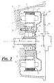
- FIG. 1 shows an electric motor 1 conventionally constituted by a wound stator 2 and a bell-shaped rotor 3 carrying permanent magnets 4 distributed regularly over the internal face 4a of its cylindrical part. .
- said electric motor 1 is coupled to an input shaft 5a of a transmission 5 including a motor vehicle for example an automatic gearbox and is disposed between a heat engine represented only by the end of a crankshaft 6 and the transmission 5 so as to transmit an auxiliary power to the latter.
- a transmission 5 including a motor vehicle for example an automatic gearbox and is disposed between a heat engine represented only by the end of a crankshaft 6 and the transmission 5 so as to transmit an auxiliary power to the latter.
- the coupling between the electric motor and the transmission 5 is achieved by means of a sleeve 3a integral with the bell of the rotor 3, for example by welding, which is provided with longitudinal grooves 7 made in its inner bore capable of meshing with complementary splines 8 made on the input shaft 5a of the transmission 5.
- stator 2 of the electric motor is fixedly mounted, in particular by fitting on the periphery of a substantially cylindrical yoke 9 having a bore for receiving the outer ring of centering bearings 10 fitted on the sleeve 3a, as visible more clearly in Figure 1.
- stator 2 thus assembled on the yoke 9 and the sleeve 3a integral with the rotor 3 constitutes a pre-assembled assembly which is advantageously, from the centering of the rotor and the stator to means of the bearing 10, provided with a constant air gap 11.
- This pre-assembled assembly can thus be coupled to the transmission shaft 5a.
- This coupling is achieved by the cooperation of the grooves 8 of the shaft 5a and those 7 of the sleeve 3a until contacting the lateral plane face 12 of the transmission housing 5 and the flat face 13 perpendicular to the 9.
- the cylinder head 9 is fixedly mounted by screw type fixing means 14 on the housing.
- a seal or a sealing paste is interposed between these two flat faces 12 and 13.
- the yoke 9 is provided with at least one cavity 16 emerging on the flat face 12 intended to be traversed by a fluid such as a cooling liquid which cooperates with conduits respectively supply 17 and discharge 18 of said liquid made in the case of the transmission 5, more clearly visible in Figures 2 and 3.
- a fluid such as a cooling liquid which cooperates with conduits respectively supply 17 and discharge 18 of said liquid made in the case of the transmission 5, more clearly visible in Figures 2 and 3.
- these ducts 17 and 18 are connected to a pump and a radiator, not shown, thus constituting the cooling circuit.
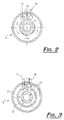
- FIG. 2 shows a first embodiment of a cooling circuit, in which the cavity 16 is provided with a longitudinal partition 20.
- This cylinder head 9 is pressed against the flat face 13 of the casing so that the respectively supply ducts 17 and exhaust ducts 18 of the cooling liquid are arranged on either side of this partition 20, in order to establish a circulation of the coolant in a circumferential manner, as represented by the arrows on this Fig.
- the yoke 9 is provided with two channels 21 and 22 having in cross section a semi-circular shape and substantially concentric with each other, thus forming an outer channel 21 and an inner channel 22.
- Each of the channels 21, 22 cooperates respectively with one of the ducts 17 or 17 for draining the coolant.
- the outer channel is fed by the supply duct 17.
- a plate is interposed between the transmission casing and the cylinder head 9 and is provided with a plurality of orifices 25, shown in FIG. Figure 3.
- Such an architecture advantageously allows a toroidal circulation of the liquid in the cylinder head 9 and also a supply at all points of the stator 2 of the liquid at the same temperature, and therefore a uniform cooling.
- FIG. 1 shows, as a guide, means for driving the heat engine with the electric motor.
- These means consist of a flange plate 26 of which one of these ends is fixedly mounted on the end of the crankshaft by means of screws 27 and whose other end is secured to the bell of the rotor 3 by means in particular of threaded studs 28 welded to the latter, as can be seen more clearly in FIG.
- the electric motor according to the present invention proves particularly easy to assemble or disassemble due to the fact of making a pre-assembly between the rotor and the stator thus constituting a unit ready to use.
- Such a unit of an electric motor finds particular application in electric or hybrid vehicles and can be compact.
- the engine according to the invention is also very effective at the level of the cooling circuit by the cooperation of supply ducts and the discharge of the cooling liquid provided on the casing of the transmission.
Landscapes
- Engineering & Computer Science (AREA)
- Power Engineering (AREA)
- Chemical & Material Sciences (AREA)
- Combustion & Propulsion (AREA)
- Transportation (AREA)
- Mechanical Engineering (AREA)
- Motor Or Generator Cooling System (AREA)
- Connection Of Motors, Electrical Generators, Mechanical Devices, And The Like (AREA)
Description
- La présente invention se rapporte à un moteur électrique destiné à être accouplé à une transmission, notamment d'un véhicule automobile.
- Elle se rapporte plus particulièrement aux moteurs à aimants permanents, dans lesquels le rotor qui porte les aimants à une forme de cloche et est disposé coaxialement autour du stator.
- Les documents
DE 196 29 346 A etDE 196 18 865 décrivent de tels moteurs. - Ce type de moteur nécessite une valeur de l'entrefer qui soit le plus faible possible afin de minimiser les pertes de rendement. Or, les aimants permanents de ce type de moteur exercent une forte attraction sur les parties ferreuses environnantes lors de la mise en place du rotor autour du stator dans une transmission, notamment de véhicule automobile. Cette difficulté de montage peut engendrer une variation de l'entrefer et ainsi une dégradation du rendement.
- Le but de la présente invention est de remédier à l'inconvénient susmentionné en proposant un moteur électrique du type décrit ci-dessus qui soit facilement montable et démontable dans une chaîne de traction d'un véhicule automobile, et qui soit également peu encombrant.
- A cet effet, la présente invention concerne un moteur électrique selon la revendication 1.
- Suivant quelques dispositions intéressantes de l'invention:
- la culasse est munie d'une cavité débouchante sur l'une de ces faces latérales plane qui coopère avec une face plane du carter de transmission en position de montage, la cavité étant destinée a être traversée par un fluide tel qu'un liquide de refroidissement qui coopère avec des conduits respectivement d'amenée et d'évacuation dudit liquide réalisés dans le carter de la transmission;
- l'accouplement de l'ensemble pré-assemblé sur l'arbre de la transmission est assuré par la coopération de cannelures réalisées respectivement sur l'arbre d'entrée de la transmission et dans l'alésage du manchon et en ce que la culasse est pourvue de moyen de fixation sur le carter.
- la cavité est munie d'une cloison longitudinale de telle sorte qu'en position de montage de la culasse les conduits respectivement d'amenée et d'évacuation du liquide sont disposés de part et d'autre de cette cloison afin d'établir une circulation du liquide de refroidissement de manière circonférentielle;
- la culasse est pourvue de deux chenaux présentant en coupe transversale une forme semi-circulaire et sensiblement concentrique l'un à l'autre formant ainsi un chenal extérieur et un chenal intérieur, et en ce que chacun des chenaux coopère respectivement avec un des conduits d'amenée ou d'évacuation du liquide de refroidissement;
- une plaque pourvue d'une pluralité d'orifices est interposée entre la face plane de la culasse et la face plane du carter de la transmission afin de permettre une circulation toroïdale du liquide de refroidissement dans la culasse;
- le chenal extérieur est alimenté par le conduit d'amenée du liquide de refroidissement.
- Les caractéristiques de l'invention mentionnées ci-dessus, ainsi que d'autres, apparaîtront plus clairement à la lecture de la description suivante d'un exemple de réalisation, en se référant aux dessins annexés sur lesquels :
- la figure 1 est une vue schématique en coupe longitudinale d'un moteur électrique suivant l'invention accouplé à une transmission notamment d'un véhicule automobile,
- la figure 2 est une vue de face de la culasse du moteur électrique suivant l'invention selon un premier mode de réalisation, et
- la figure 3 est une vue de face similaire à la figure 2 selon un second mode de réalisation.
- On a représenté à la figure 1, un moteur électrique 1 constitué de manière classique d'un stator bobiné 2 et d'un rotor 3 en forme de cloche portant des aimants permanents 4 répartis de façon régulière sur la face interne 4a de sa partie cylindrique.
- Comme visible sur cette figure, ledit moteur électrique 1 est accouplé à un arbre d'entrée 5a d'une transmission 5 notamment d'un véhicule automobile par exemple une boîte de vitesses automatique et est disposé entre un moteur thermique représenté uniquement par l'extrémité d'un vilebrequin 6 et la transmission 5 de manière à transmettre une puissance auxiliaire à cette dernière.
- L'accouplement entre le moteur électrique et la transmission 5 est réalisé par l'intermédiaire d'un manchon 3a solidaire de la cloche du rotor 3, par exemple par soudure, qui est pourvu de cannelures longitudinales 7 réalisé dans son alésage intérieur aptes à engrener avec des cannelures complémentaires 8 réalisées sur l'arbre d'entrée 5a de la transmission 5.
- Selon la présente invention, le stator 2 du moteur électrique est monté fixement, notamment par emmanchement sur le pourtour d'une culasse 9 de forme sensiblement cylindrique comportant un alésage destiné à recevoir la bague extérieure de roulements de centrage 10 emmanchés sur le manchon 3a, comme visible plus clairement sur la figure 1.
- On comprend aisément à la lecture de la description ci-dessus que le stator 2 ainsi assemblé sur la culasse 9 et le manchon 3a solidaire du rotor 3 constitue un ensemble pré-assemblé qui est avantageusement, de part le centrage du rotor et du stator au moyen des roulement 10, muni d'un entrefer 11 constant. Cet ensemble pré-assemblé peut ainsi être accouplé sur l'arbre de la transmission 5a.
- On notera que le montage du rotor autour du stator est effectué préalablement en usine avec un outillage particulier afin d'assurer un centrage adéquat entre ces deux pièces.
- Cet accouplement est réalisé par la coopération des cannelures 8 de l'arbre 5a et celles 7 du manchon 3a jusqu'à la mise en contact de la face plane latéral 12 du carter de la transmission 5 et de la face plane 13 perpendiculaire à l'axe du moteur de la culasse 9. Afin d'assurer une stabilité à l'ensemble, la culasse 9 est montée fixement par des moyens de fixation du type vis 14 sur le carter.
- Avantageusement, un joint d'étanchéité ou une pâte d'étanchéité est interposé entre ces deux faces planes 12 et 13.
- On notera que l'accès aux vis 14 est réalisé par l'intermédiaire de trous 15 réalisés parallèlement à l'axe du moteur dans la cloche du rotor 3 au droit des vis 14, comme visible plus clairement sur la figure 1.
- La culasse 9 est munie d'au moins une cavité 16 débouchante sur la face plane 12 destinée a être traversée par un fluide tel qu'un liquide de refroidissement qui coopère avec des conduits respectivement d'amenée 17 et d'évacuation 18 dudit liquide réalisés dans le carter de la transmission 5, visible plus clairement sur les figures 2 et 3. De manière classique ces conduits 17 et 18 sont reliés à une pompe et à un radiateur, non représentés, constituant ainsi le circuit de refroidissement.
- On a représenté à la figure 2, un premier mode de réalisation d'un circuit de refroidissement, dans lequel la cavité 16 est munie d'une cloison longitudinale 20. Cette culasse 9 est plaquée contre la face plane 13 du carter de telle sorte que les conduits respectivement d'amenée 17 et d'évacuation 18 du liquide de refroidissement sont disposés de part et d'autre de cette cloison 20, afin d'établir une circulation du liquide de refroidissement de manière circonférentielle, comme représentée par les flèches sur cette figure.
- Suivant un autre mode de réalisation, représenté à la figure 3, la culasse 9 est pourvue de deux chenaux 21 et 22 présentant en coupe transversale une forme semi-circulaire et sensiblement concentrique l'un à l'autre formant ainsi un chenal extérieur 21 et un chenal intérieur 22. Chacun des chenaux 21, 22 coopère respectivement avec un des conduits soit d'amenée 17 ou d'évacuation 18 du liquide de refroidissement. Selon un mode préférentiel de réalisation le chenal extérieur est alimenté par le conduit d'amenée 17.
- Afin de permettre la circulation du liquide de refroidissement d'un chenal à l'autre, une plaque, non représentée, est interposée entre le carter de la transmission et la culasse 9 et est pourvue d'une pluralité d'orifices 25, représentée en silhouette sur la figure 3. Une telle architecture permet avantageusement une circulation toroïdale du liquide dans la culasse 9 et également une amenée en tous points du stator 2 du liquide à la même température, et par conséquent un refroidissement uniforme.
- On a représenté sur la figure 1, a titre indicatif, des moyens d'entraînement du moteur thermique avec le moteur électrique. Ces moyens sont constitués d'un flasque 26 en tôle dont l'une de ces extrémités est monté fixement sur l'extrémité du vilebrequin au moyen de vis 27 et dont l'autre extrémité est solidaire de la cloche du rotor 3 au moyen notamment de plots taraudés 28 soudés sur ce dernier, comme visible plus clairement à la figure 1.
- On comprend à la lecture de la description ci-dessus que le moteur électrique selon la présente invention s'avère particulièrement facile à monter ou à démonter du fait de la réalisation d'un pré-montage entre le rotor et le stator constituant ainsi une unité prêt à l'emploi. Une telle unité d'un moteur électrique trouve particulièrement une application dans les véhicules électriques ou hybrides et permet d'être peu encombrant.
- Le moteur selon l'invention s'avère également très efficace au niveau du circuit de refroidissement par la coopération de conduits d'amenée et d'évacuation du liquide de refroidissement prévu sur le carter de la transmission.
- Bien que l'invention ait été décrite en liaison avec un mode de réalisation particulier, elle comprend tous les équivalents techniques des moyens décrits.
Claims (6)
- Moteur électrique du type à aimants permanents destiné à être accouplé à une transmission (5), notamment d'un véhicule automobile, comprenant un stator bobiné (2) et un rotor (3) en forme de cloche portant des aimants permanents (4) répartis de façon régulière sur la face interne (4a) de sa partie cylindrique, le stator (2) du moteur électrique (1) est monté fixement, sur le pourtour d'une culasse (9) de forme sensiblement cylindrique comportant un alésage recevant la bague extérieure de roulements de centrage (10) emmanchés sur un manchon (3a) solidaire de la cloche du rotor (3) formant ainsi un ensemble pré-assemblé apte à être accouplé à un arbre d'entrée (5a) de la transmission (5), caractérisé en ce que la culasse (9) est munie d'au moins une cavité (16) débouchante sur l'une de ses faces latérales plane (13) alignée avec une des faces latérales du stator (2) et qui est destinée coopérer avec une face plane (12) du carter de transmission (5) en position de montage, la cavité (16) étant destinée a être traversée par un fluide tel qu'un liquide de refroidissement, ladite cavité étant destiné à coopérer avec des conduits respectivement d'amenée (17) et d'évacuation (18) dudit liquide réalisés dans le carter de la transmission (5).
- Moteur selon la revendication 1, caractérisé en ce que l'accouplement de l'ensemble pré-assemblé sur l'arbre (5a) de la transmission (5) est assuré par la coopération de cannelures (7; 8) réalisées respectivement sur l'arbre d'entrée (5a) de la transmission et dans l'alésage du manchon (3a) et en ce que la culasse (9) est pourvue de moyen de fixation (14) sur le carter de la transmission.
- Moteur selon l'une quelconque des revendications précédentes, caractérisé en ce que la cavité (16) est munie d'une cloison longitudinale (20) de telle sorte qu'en position de montage de la culasse (9) les conduits respectivement d'amenée (17) et d'évacuation (18) du liquide sont disposés de part et d'autre de cette cloison (20) afin d'établir une circulation du liquide de refroidissement de manière circonférentielle.
- Moteur selon l'une quelconque des revendications 1 à 2, caractérisé en ce que la cavité de la culasse (9) est constituée de deux chenaux (21, 22) présentant en coupe transversale une forme semi-circulaire et sensiblement concentrique l'un à l'autre formant ainsi un chenal extérieur (21) et un chenal intérieur (22), et en ce que chacun des chenaux coopère respectivement avec un des conduits d'amenée (17) ou d'évacuation (18) du liquide de refroidissement.
- Moteur selon la revendication 4, caractérisé en ce qu'une plaque pourvue d'une pluralité d'orifices (25) est interposée entre la face plane (13) de la culasse (9) et la face plane (12) du carter de la transmission (5) afin de permettre une circulation toroïdale du liquide de refroidissement dans la culasse (9).
- Moteur selon la revendication 4, caractérisée en ce que le chenal extérieur (21) est alimenté par le conduit d'amenée (17) du liquide de refroidissement.
Applications Claiming Priority (2)
| Application Number | Priority Date | Filing Date | Title |
|---|---|---|---|
| FR9810969A FR2782856B1 (fr) | 1998-09-02 | 1998-09-02 | Moteur electrique destine a etre accouple a une transmission notamment d'un vehicule automobile |
| FR9810969 | 1998-09-02 |
Publications (2)
| Publication Number | Publication Date |
|---|---|
| EP0984548A1 EP0984548A1 (fr) | 2000-03-08 |
| EP0984548B1 true EP0984548B1 (fr) | 2007-08-01 |
Family
ID=9530049
Family Applications (1)
| Application Number | Title | Priority Date | Filing Date |
|---|---|---|---|
| EP99402164A Expired - Lifetime EP0984548B1 (fr) | 1998-09-02 | 1999-09-01 | Moteur électrique destiné à être accouplé à une transmission, notamment d'un véhicule automobile |
Country Status (4)
| Country | Link |
|---|---|
| EP (1) | EP0984548B1 (fr) |
| DE (1) | DE69936693T2 (fr) |
| ES (1) | ES2291012T3 (fr) |
| FR (1) | FR2782856B1 (fr) |
Cited By (1)
| Publication number | Priority date | Publication date | Assignee | Title |
|---|---|---|---|---|
| US20250030303A1 (en) * | 2023-07-21 | 2025-01-23 | Borgwarner Inc. | Housing component for an electric motor and electric motor |
Families Citing this family (13)
| Publication number | Priority date | Publication date | Assignee | Title |
|---|---|---|---|---|
| FR2809880B1 (fr) * | 2000-06-05 | 2002-08-30 | Peugeot Citroen Automobiles Sa | Moteur electrique pour vehicule a propulsion hybride |
| ES2302621B1 (es) * | 2006-07-18 | 2009-05-21 | GAMESA INNOVATION & TECHNOLOGY, S.L. | Generador electrico refrigerado con tubos embebidos en su cubierta. |
| FR2912695B1 (fr) * | 2007-02-21 | 2009-08-28 | Renault Soc Par Actions Simpli | Transmission a derivation de puissance a machine electrique independante. |
| AT10549U1 (de) | 2007-06-06 | 2009-05-15 | Steyr Motors Gmbh | Aus einer verbrennungskraftmaschine und einem generator bestehendes stromerzeugungsaggregat |
| DE102007051227A1 (de) * | 2007-10-26 | 2009-04-30 | Schaeffler Kg | Elektrische Direktantriebsvorrichtung |
| CN103475145B (zh) * | 2013-09-03 | 2015-10-28 | 深圳红河马智能数字动力技术有限公司 | 电动汽车电机的端盖及其电机 |
| CN104325893A (zh) * | 2014-11-28 | 2015-02-04 | 冯军 | 电动车辆能量转换系统 |
| CN106763233A (zh) * | 2017-02-13 | 2017-05-31 | 兖州煤业股份有限公司 | 一种冷却短轴及包含该短轴的破碎机 |
| CN106972690B (zh) * | 2017-05-19 | 2022-09-06 | 宁德时代电机科技有限公司 | 集成制动器差动无级变速器的混合动力永磁外转子双电机 |
| CN108644273B (zh) * | 2018-06-20 | 2024-03-12 | 重庆市涪陵区李渡星耀橡塑有限公司 | 一种汽车散热器橡胶垫 |
| CN109412328A (zh) * | 2018-11-02 | 2019-03-01 | 宁波安信数控技术有限公司 | 一种汽车增程器用永磁发电机 |
| TWI816123B (zh) * | 2021-05-14 | 2023-09-21 | 士林電機廠股份有限公司 | 具有驅動器之液冷動力系統 |
| DE102022117847A1 (de) * | 2022-07-18 | 2024-01-18 | Dr. Ing. H.C. F. Porsche Aktiengesellschaft | Vorrichtung zum Kühlen einer elektrischen Antriebsmaschine |
Family Cites Families (7)
| Publication number | Priority date | Publication date | Assignee | Title |
|---|---|---|---|---|
| EP0124547A1 (fr) * | 1982-11-01 | 1984-11-14 | Storage Technology Partners Ii | Moteur sans balai a courant continu avec cuvette d'aimant inversee |
| JP2830050B2 (ja) * | 1989-05-18 | 1998-12-02 | 松下電器産業株式会社 | アウターロータモータ |
| DE4404791C1 (de) * | 1994-02-08 | 1995-03-30 | Mannesmann Ag | Baueinheit aus einem Verbrennungsmotor und einem elektrischen Generator |
| US5654598A (en) * | 1995-12-14 | 1997-08-05 | Siemens Electric Limited | Brushless motor with inside mounted single bearing |
| DE19547745A1 (de) * | 1995-12-20 | 1997-06-26 | Bosch Siemens Hausgeraete | Antriebsvorrichtung für eine von vorn beschickbare Waschmaschine |
| DE19655301B4 (de) * | 1996-05-10 | 2006-12-28 | Zf Sachs Ag | Antriebsanordnung für ein Kraftfahrzeug |
| DE19629346C2 (de) * | 1996-07-20 | 1998-05-14 | Mannesmann Sachs Ag | Hybridantrieb |
-
1998
- 1998-09-02 FR FR9810969A patent/FR2782856B1/fr not_active Expired - Fee Related
-
1999
- 1999-09-01 DE DE69936693T patent/DE69936693T2/de not_active Expired - Lifetime
- 1999-09-01 EP EP99402164A patent/EP0984548B1/fr not_active Expired - Lifetime
- 1999-09-01 ES ES99402164T patent/ES2291012T3/es not_active Expired - Lifetime
Cited By (1)
| Publication number | Priority date | Publication date | Assignee | Title |
|---|---|---|---|---|
| US20250030303A1 (en) * | 2023-07-21 | 2025-01-23 | Borgwarner Inc. | Housing component for an electric motor and electric motor |
Also Published As
| Publication number | Publication date |
|---|---|
| FR2782856B1 (fr) | 2002-01-18 |
| DE69936693D1 (de) | 2007-09-13 |
| FR2782856A1 (fr) | 2000-03-03 |
| DE69936693T2 (de) | 2008-04-30 |
| ES2291012T3 (es) | 2008-02-16 |
| EP0984548A1 (fr) | 2000-03-08 |
Similar Documents
| Publication | Publication Date | Title |
|---|---|---|
| EP0984548B1 (fr) | Moteur électrique destiné à être accouplé à une transmission, notamment d'un véhicule automobile | |
| FR2719261A1 (fr) | Dispositif hydrodynamique servant de générateur de chauffage pour un véhicule automobile. | |
| CA2588956C (fr) | Boitier d'accessoires dans un moteur d'avion tel qu'un turboreacteur | |
| FR2806223A1 (fr) | Machine electrique tournante polyphasee | |
| FR2803452A1 (fr) | Dispositif de fixation d'un equipement electrique, tel qu'un alternateur-demarreur, dans un carter d'embrayage d'un vehicule automobile | |
| EP3879133B1 (fr) | Double embrayage humide | |
| FR2766235A1 (fr) | Dispositif de fixation d'un groupe moto-ventilateur sur un element d'un vehicule automobile, notamment un echangeur de chaleur | |
| WO2000031411A1 (fr) | Groupe motopropulseur comportant une machine electrique interposee entre le moteur thermique et la transmission | |
| FR2765296A1 (fr) | Appareil d'accouplement hydrocinetique a embrayage de verrouillage, pour vehicule automobile | |
| EP4083489B1 (fr) | Connecteur | |
| FR3086124A1 (fr) | Ensemble a machine electrique tournante et element reducteur evitant les infiltrations dans la machine electrique tournante | |
| WO2019149540A1 (fr) | Actionneur d'embrayage | |
| EP3850235A1 (fr) | Machine électrique tournante munie d'un manchon de liaison intégrant un amortisseur | |
| FR2881587A1 (fr) | Dispositif permettant le refroidissement d'une machine electrique tournante par circulation d'un fluide de refroidissement | |
| FR2881382A1 (fr) | Dispositif d'accouplement entre le rotor d'une machine electrique tournante reversible et l'arbre primaire de la boite de vitesses d'un moteur thermique d'un vehicule automobile | |
| EP0983435A1 (fr) | Bloc de prechauffage du liquide de refroidissement pour vehicule a moteur thermique | |
| FR3069597B1 (fr) | Actionneur d'embrayage | |
| FR2766894A1 (fr) | Appareil d'accouplement hydrocinetique a piece d'entrainement de languettes, notamment pour vehicule automobile | |
| FR2809880A1 (fr) | Moteur electrique pour vehicule a propulsion hybride | |
| WO2026087458A1 (fr) | Carter de machine electrique | |
| FR2594184A1 (fr) | Pompe a liquide, notamment pompe a eau pour vehicule automobile | |
| JP2003158851A (ja) | 車両用モータの配線接続装置 | |
| EP3746670B1 (fr) | Actionneur d'embrayage | |
| FR3154259A1 (fr) | Machine electrique comprenant des plaques de refroidissement | |
| FR3069595B1 (fr) | Actionneur d'embrayage |
Legal Events
| Date | Code | Title | Description |
|---|---|---|---|
| PUAI | Public reference made under article 153(3) epc to a published international application that has entered the european phase |
Free format text: ORIGINAL CODE: 0009012 |
|
| AK | Designated contracting states |
Kind code of ref document: A1 Designated state(s): DE ES FR GB IT |
|
| AX | Request for extension of the european patent |
Free format text: AL;LT;LV;MK;RO;SI |
|
| 17P | Request for examination filed |
Effective date: 20000622 |
|
| AKX | Designation fees paid |
Free format text: DE ES FR GB IT |
|
| GRAP | Despatch of communication of intention to grant a patent |
Free format text: ORIGINAL CODE: EPIDOSNIGR1 |
|
| GRAS | Grant fee paid |
Free format text: ORIGINAL CODE: EPIDOSNIGR3 |
|
| GRAA | (expected) grant |
Free format text: ORIGINAL CODE: 0009210 |
|
| AK | Designated contracting states |
Kind code of ref document: B1 Designated state(s): DE ES FR GB IT |
|
| REG | Reference to a national code |
Ref country code: GB Ref legal event code: FG4D Free format text: NOT ENGLISH |
|
| REF | Corresponds to: |
Ref document number: 69936693 Country of ref document: DE Date of ref document: 20070913 Kind code of ref document: P |
|
| GBT | Gb: translation of ep patent filed (gb section 77(6)(a)/1977) |
Effective date: 20071002 |
|
| REG | Reference to a national code |
Ref country code: ES Ref legal event code: FG2A Ref document number: 2291012 Country of ref document: ES Kind code of ref document: T3 |
|
| REG | Reference to a national code |
Ref country code: GB Ref legal event code: 746 Effective date: 20080329 |
|
| PLBE | No opposition filed within time limit |
Free format text: ORIGINAL CODE: 0009261 |
|
| STAA | Information on the status of an ep patent application or granted ep patent |
Free format text: STATUS: NO OPPOSITION FILED WITHIN TIME LIMIT |
|
| 26N | No opposition filed |
Effective date: 20080506 |
|
| PGFP | Annual fee paid to national office [announced via postgrant information from national office to epo] |
Ref country code: ES Payment date: 20080924 Year of fee payment: 10 |
|
| PGFP | Annual fee paid to national office [announced via postgrant information from national office to epo] |
Ref country code: IT Payment date: 20080913 Year of fee payment: 10 |
|
| PG25 | Lapsed in a contracting state [announced via postgrant information from national office to epo] |
Ref country code: IT Free format text: LAPSE BECAUSE OF NON-PAYMENT OF DUE FEES Effective date: 20090901 |
|
| REG | Reference to a national code |
Ref country code: ES Ref legal event code: FD2A Effective date: 20110714 |
|
| PG25 | Lapsed in a contracting state [announced via postgrant information from national office to epo] |
Ref country code: ES Free format text: LAPSE BECAUSE OF NON-PAYMENT OF DUE FEES Effective date: 20110704 |
|
| PG25 | Lapsed in a contracting state [announced via postgrant information from national office to epo] |
Ref country code: ES Free format text: LAPSE BECAUSE OF NON-PAYMENT OF DUE FEES Effective date: 20090902 |
|
| PGFP | Annual fee paid to national office [announced via postgrant information from national office to epo] |
Ref country code: GB Payment date: 20110830 Year of fee payment: 13 |
|
| GBPC | Gb: european patent ceased through non-payment of renewal fee |
Effective date: 20120901 |
|
| PG25 | Lapsed in a contracting state [announced via postgrant information from national office to epo] |
Ref country code: GB Free format text: LAPSE BECAUSE OF NON-PAYMENT OF DUE FEES Effective date: 20120901 |
|
| PGFP | Annual fee paid to national office [announced via postgrant information from national office to epo] |
Ref country code: DE Payment date: 20130820 Year of fee payment: 15 |
|
| REG | Reference to a national code |
Ref country code: DE Ref legal event code: R119 Ref document number: 69936693 Country of ref document: DE |
|
| PG25 | Lapsed in a contracting state [announced via postgrant information from national office to epo] |
Ref country code: DE Free format text: LAPSE BECAUSE OF NON-PAYMENT OF DUE FEES Effective date: 20150401 |
|
| REG | Reference to a national code |
Ref country code: FR Ref legal event code: PLFP Year of fee payment: 18 |
|
| PGFP | Annual fee paid to national office [announced via postgrant information from national office to epo] |
Ref country code: FR Payment date: 20160822 Year of fee payment: 18 |
|
| REG | Reference to a national code |
Ref country code: FR Ref legal event code: ST Effective date: 20180531 |
|
| PG25 | Lapsed in a contracting state [announced via postgrant information from national office to epo] |
Ref country code: FR Free format text: LAPSE BECAUSE OF NON-PAYMENT OF DUE FEES Effective date: 20171002 |