EP0984663B1 - Dispositif transducteur pour prothèses auditives partiellement ou totalment implantées - Google Patents
Dispositif transducteur pour prothèses auditives partiellement ou totalment implantées Download PDFInfo
- Publication number
- EP0984663B1 EP0984663B1 EP98121495A EP98121495A EP0984663B1 EP 0984663 B1 EP0984663 B1 EP 0984663B1 EP 98121495 A EP98121495 A EP 98121495A EP 98121495 A EP98121495 A EP 98121495A EP 0984663 B1 EP0984663 B1 EP 0984663B1
- Authority
- EP
- European Patent Office
- Prior art keywords
- housing
- transducer arrangement
- oscillatable
- membrane
- coupling element
- Prior art date
- Legal status (The legal status is an assumption and is not a legal conclusion. Google has not performed a legal analysis and makes no representation as to the accuracy of the status listed.)
- Expired - Lifetime
Links
Images

Classifications
-
- H—ELECTRICITY
- H04—ELECTRIC COMMUNICATION TECHNIQUE
- H04R—LOUDSPEAKERS, MICROPHONES, GRAMOPHONE PICK-UPS OR LIKE ACOUSTIC ELECTROMECHANICAL TRANSDUCERS; ELECTRIC HEARING AIDS; PUBLIC ADDRESS SYSTEMS
- H04R25/00—Electric hearing aids
- H04R25/60—Mounting or interconnection of hearing aid parts, e.g. inside tips, housings or to ossicles
- H04R25/604—Mounting or interconnection of hearing aid parts, e.g. inside tips, housings or to ossicles of acoustic or vibrational transducers
- H04R25/606—Mounting or interconnection of hearing aid parts, e.g. inside tips, housings or to ossicles of acoustic or vibrational transducers acting directly on the eardrum, the ossicles or the skull, e.g. mastoid, tooth, maxillary or mandibular bone, or mechanically stimulating the cochlea, e.g. at the oval window
-
- H—ELECTRICITY
- H04—ELECTRIC COMMUNICATION TECHNIQUE
- H04R—LOUDSPEAKERS, MICROPHONES, GRAMOPHONE PICK-UPS OR LIKE ACOUSTIC ELECTROMECHANICAL TRANSDUCERS; ELECTRIC HEARING AIDS; PUBLIC ADDRESS SYSTEMS
- H04R2225/00—Details of deaf aids covered by H04R25/00, not provided for in any of its subgroups
- H04R2225/67—Implantable hearing aids or parts thereof not covered by H04R25/606
-
- H—ELECTRICITY
- H04—ELECTRIC COMMUNICATION TECHNIQUE
- H04R—LOUDSPEAKERS, MICROPHONES, GRAMOPHONE PICK-UPS OR LIKE ACOUSTIC ELECTROMECHANICAL TRANSDUCERS; ELECTRIC HEARING AIDS; PUBLIC ADDRESS SYSTEMS
- H04R25/00—Electric hearing aids
- H04R25/55—Electric hearing aids using an external connection, either wireless or wired
- H04R25/558—Remote control, e.g. of amplification, frequency
Definitions
- the present invention relates to a transducer assembly for partially or fully implantable hearing for direct mechanical excitation of the middle or inner ear, provided with a fixable at the implantation with respect to the skull housing and a movable with respect to the housing, mechanically rigid coupling element, wherein in the Housing an electromechanical transducer is housed, with which the coupling element can vibrate, which are transmitted after implantation of the transducer assembly to a middle ear ossicle or directly to the inner ear.
- Such a transducer arrangement is made EP 0 499 940 known.
- a wall of the housing as a vibratable membrane, which constitutes an electromechanically active heteromorph composite element with a piezoelectric ceramic disk applied on the inside.
- the coupling element driven via the piezoelectric ceramic disc causes deflections at low frequencies to be transmitted to the middle ear ossicle or directly to the inner ear that may be inadequate for adequate volume levels for moderate and severe hearing losses. This applies in particular to the low electrical voltages prescribed for an implant.
- an implantable middle ear transducer which is an electromagnetic motor housed in a hermetically sealed stainless steel housing which drives a biocompatible probe tip.
- the probe tip engages in a laser beam formed opening of the incus. It is not clear how the electromagnetic motor is built, nor how vibrations are transmitted from the electromagnetic motor to the probe tip.
- the electromechanical transducer is designed as an electromagnet assembly having a component fixed with respect to the housing and a vibratable component, which is in communication with the coupling element, that Vibrations of the oscillatory component are transmitted to the coupling element.
- a wall of the housing is designed as a vibratable membrane, on the inside of the oscillatory component is attached and the outside of the coupling element is connected to the inside of the diaphragm and the oscillatory component forming permanent magnet is connected, and fixed an electromagnetic coil in the housing is mounted to enable the permanent magnet to vibrate, wherein the permanent magnet is formed as a magnetic pin and the coil is a toroidal coil having a central opening, in which the magnetic pin is immersed.
- the solution according to the invention has the advantage that the transducer assembly according to simple and easy as the piezoelectric transducer according to EP 0 499 940 can be implanted because the transducer housing with respect fix on the bone structure of the skull.
- a frequency response of the transducer which is particularly favorable even for low frequencies of the audible range can be achieved, so that an adequate hearing impression is made possible with sufficient loudness level with the necessarily low electrical voltages for an implant.
- a particularly small moving mass transducer assembly is obtained which can rapidly and faithfully follow changes in the electrical signal applied to the solenoid.
- the housing is expediently designed as a hermetically sealed and biocompatible housing. It is advantageously cylindrical, and has a peripheral wall and two substantially mutually parallel, circular end walls, one of which forms the oscillatable membrane, while the other may be integrally connected to the peripheral wall of the housing.
- both the oscillatory component and the coupling element are fastened substantially in the center of the housing end surface forming the oscillatable diaphragm.
- the invention further provides a fully or partially implantable hearing aid which is provided with a transducer assembly of the type disclosed herein.
- FIG. 1 an implantable transducer assembly 10 of a hearing aid for direct mechanical excitation of the middle or inner ear is shown.
- a trained as a microphone 58 transducer which is preferably also implanted.
- the transducer assembly 10 is provided with a hermetically sealed, biocompatible, cylindrical housing 14, preferably made of Metal, such as titanium, niobium, tantalum, iridium or their alloys provided.
- the housing 14 is filled with inert gas 16.
- the housing 14 has a peripheral wall 11 and two circular end walls 12 and 18 extending perpendicular to the peripheral wall 11.
- the one end wall of the housing 14 is formed as a thin, oscillatable membrane 18, attached to the outside, preferably in the center of the outside, a mechanically rigid coupling element 20 for mechanical vibration coupling to a middle ear ossicle or directly to the inner ear, for example, welded or glued , is.
- the other end face 12 is integrally connected to the peripheral wall 11 of the housing
- a pin-shaped permanent magnet 30 is fixed, which dips into a central opening of the toroidal coil 32 and is displaceable therein.
- the coil 32 is fixedly connected in a manner not shown with the housing 14, for example glued to this.
- an electrically insulating, hermetically sealed passage 26 is used in the end wall 12. Connecting wires 34 of the coil 32 are connected to outwardly led out of the housing 14 electrical terminals 36.
- the coupling element 20 may in particular be designed as a coupling rod and be connected to the ossicle chain, for example via a thin wire or hollow wire bow or a bracket made of a carbon fiber reinforced composite material. Suitable arrangements of this type are in the older DE patent application 197 38 587.7 explained in more detail.
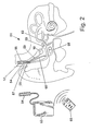
- Fig. 2 shows an implanted hearing aid, generally designated 51, which is equipped with a transducer assembly 10 of the type described above.
- the hearing device 51 also has an accumulator unit 53, a charge receiving coil 54 and an electronic module 55.
- the components 53, 54 and 55 are housed in a hermetically sealed housing 56 which is implanted in the mastoid 57 and fixed with respect to the skull.
- the transducer assembly 10 and the microphone 58 via lines 59 and 60 are connected to the electronic module 55.
- the coupling element 20 is coupled to the ossicular chain 62.
- To a portable charging unit 63 includes a charging coil 64, the transcutaneous charging of the accumulator unit 53 with the charge receiving coil 54 can be inductively coupled.
- a remote control unit is indicated at 65.
- Such a hearing aid is for example off U.S. Patent 5,277,694 known and therefore needs no further description.
Landscapes
- Health & Medical Sciences (AREA)
- General Health & Medical Sciences (AREA)
- Otolaryngology (AREA)
- Neurosurgery (AREA)
- Physics & Mathematics (AREA)
- Engineering & Computer Science (AREA)
- Acoustics & Sound (AREA)
- Signal Processing (AREA)
- Prostheses (AREA)
- Electrotherapy Devices (AREA)
Claims (8)
- Dispositif transducteur pour prothèses auditives partiellement ou totalement implantables pour l'excitation mécanique directe de l'oreille moyenne ou de l'oreille interne, doté d'un boîtier (14) pouvant être fixé sur le point d'implantation par rapport au crâne et d'un élément de couplage (20) mobile par rapport au boîtier et rigide mécaniquement, un transducteur (30, 32) électromécanique étant logé dans le boîtier, avec lequel l'élément de couplage peut être mis en vibration, qui sont transmises, après l'implantation du dispositif transducteur effectuée à un osselet de l'oreille moyenne ou directement à l'oreille interne, le transducteur électromécanique étant conçu comme dispositif à électro-aimant (30, 32), qui présente un composant (32) vissé par rapport au boîtier et un composant (30) vibrant, lequel est en liaison avec l'élément de couplage (20) de telle sorte que les vibrations du composant vibrant sont transmises à l'élément de couplage, caractérisé en ce qu'une paroi du boîtier (14) est conçue comme membrane (18) vibrante, sur le côté intérieur de laquelle le composant (30) vibrant est fixé, l'élément de couplage (20) étant relié au côté extérieur de la membrane et un aimant permanent (30) formant le composant vibrant étant relié au côté intérieur de la membrane (18), et une bobine (32) électromagnétique est placée fixement dans le boîtier (14) afin de mettre l'aimant permanent en vibration, l'aimant permanent (30) étant conçu comme une broche magnétique et la bobine (32) étant une bobine annulaire avec une ouverture centrale (33), dans laquelle la broche magnétique plonge.
- Agencement transducteur selon la revendication 1, caractérisé en ce que le boîtier (14) est conçu comme boîtier hermétiquement étanche et biocompatible.
- Dispositif transducteur selon l'une quelconque des revendications précédentes, caractérisé en ce que le boîtier (14) est cylindrique et présente une paroi périphérique (11) ainsi que deux parois frontales (12, 18) de forme circulaire, agencées sensiblement parallèlement.
- Agencement transducteur selon la revendication 3, caractérisé en ce que l'une des parois frontales du boîtier (14) forme la membrane (18) vibrante.
- Agencement transducteur selon la revendication 4, caractérisé en ce que l'autre paroi frontale (12) du boîtier (14) est reliée d'une seule pièce à la paroi périphérique (11) du boîtier.
- Agencement transducteur selon l'une quelconque des revendications 3 à 5, caractérisé en ce que le composant (30) vibrant est sensiblement au centre de la surface frontale du boîtier formant la membrane (18) vibrante.
- Agencement transducteur selon l'une quelconque des revendications 3 à 6, caractérisé en ce que l'élément de couplage (20) est fixé sensiblement au centre de la surface frontale du boîtier formant la membrane (18) vibrante.
- Prothèse auditive entièrement ou partiellement implantable dotée d'un dispositif transducteur (10) selon l'une quelconque des revendications précédentes.
Applications Claiming Priority (2)
| Application Number | Priority Date | Filing Date | Title |
|---|---|---|---|
| DE19840212A DE19840212C2 (de) | 1998-09-03 | 1998-09-03 | Wandleranordnung für teil- oder vollimplantierbare Hörgeräte |
| DE19840212 | 1998-09-03 |
Publications (3)
| Publication Number | Publication Date |
|---|---|
| EP0984663A2 EP0984663A2 (fr) | 2000-03-08 |
| EP0984663A3 EP0984663A3 (fr) | 2006-05-17 |
| EP0984663B1 true EP0984663B1 (fr) | 2010-10-27 |
Family
ID=7879710
Family Applications (1)
| Application Number | Title | Priority Date | Filing Date |
|---|---|---|---|
| EP98121495A Expired - Lifetime EP0984663B1 (fr) | 1998-09-03 | 1998-11-12 | Dispositif transducteur pour prothèses auditives partiellement ou totalment implantées |
Country Status (6)
| Country | Link |
|---|---|
| US (1) | US6162169A (fr) |
| EP (1) | EP0984663B1 (fr) |
| AU (1) | AU760815B2 (fr) |
| CA (1) | CA2274211C (fr) |
| DE (2) | DE19840212C2 (fr) |
| DK (1) | DK0984663T3 (fr) |
Families Citing this family (25)
| Publication number | Priority date | Publication date | Assignee | Title |
|---|---|---|---|---|
| US6364825B1 (en) | 1998-09-24 | 2002-04-02 | St. Croix Medical, Inc. | Method and apparatus for improving signal quality in implantable hearing systems |
| DE19858399C2 (de) * | 1998-12-17 | 2003-02-20 | Phonak Ag Staefa | Elektroakustischer Wandler für Hörgeräte zur Luftschallabstrahlung in den äußeren Gehörgang |
| DE19859171C2 (de) * | 1998-12-21 | 2000-11-09 | Implex Hear Tech Ag | Implantierbares Hörgerät mit Tinnitusmaskierer oder Noiser |
| DE19931788C1 (de) | 1999-07-08 | 2000-11-30 | Implex Hear Tech Ag | Anordnung zum mechanischen Ankoppeln eines Treibers an eine Ankoppelstelle der Ossikelkette |
| DE19935029C2 (de) | 1999-07-26 | 2003-02-13 | Phonak Ag Staefa | Implantierbare Anordnung zum mechanischen Ankoppeln eines Treiberteils an eine Ankoppelstelle |
| DE10015421C2 (de) | 2000-03-28 | 2002-07-04 | Implex Ag Hearing Technology I | Teil- oder vollimplantierbares Hörsystem |
| DE10018334C1 (de) | 2000-04-13 | 2002-02-28 | Implex Hear Tech Ag | Mindestens teilimplantierbares System zur Rehabilitation einer Hörstörung |
| DE10031832C2 (de) | 2000-06-30 | 2003-04-30 | Cochlear Ltd | Hörgerät zur Rehabilitation einer Hörstörung |
| DE10039401C2 (de) | 2000-08-11 | 2002-06-13 | Implex Ag Hearing Technology I | Mindestens teilweise implantierbares Hörsystem |
| DE10041726C1 (de) | 2000-08-25 | 2002-05-23 | Implex Ag Hearing Technology I | Implantierbares Hörsystem mit Mitteln zur Messung der Ankopplungsqualität |
| DE10047388C1 (de) * | 2000-09-25 | 2002-01-10 | Implex Hear Tech Ag | Mindestens teilweise implantierbares Hörsystem |
| DE10114838A1 (de) * | 2001-03-26 | 2002-10-10 | Implex Ag Hearing Technology I | Vollständig implantierbares Hörsystem |
| US6875166B2 (en) * | 2001-09-06 | 2005-04-05 | St. Croix Medical, Inc. | Method for creating a coupling between a device and an ear structure in an implantable hearing assistance device |
| US7278963B2 (en) * | 2003-01-27 | 2007-10-09 | Otologics, Llc | Implantable hearing aid transducer with advanceable actuator to facilitate coupling with the auditory system |
| EP1422971B1 (fr) * | 2002-11-20 | 2012-11-07 | Phonak Ag | Transducteur implantable pour des systèmes auditifs et procédé d'ajustement de la réponse en fréquence d'un tel transducteur |
| US7273447B2 (en) * | 2004-04-09 | 2007-09-25 | Otologics, Llc | Implantable hearing aid transducer retention apparatus |
| JP4864901B2 (ja) * | 2004-11-30 | 2012-02-01 | アドバンスド・バイオニクス・アクチエンゲゼルシャフト | 補聴器用の埋込式アクチュエータ |
| US20070127757A2 (en) * | 2005-07-18 | 2007-06-07 | Soundquest, Inc. | Behind-The-Ear-Auditory Device |
| WO2007011806A2 (fr) * | 2005-07-18 | 2007-01-25 | Soundquest, Inc. | Dispositif auditif place derriere l'oreille |
| WO2008049933A2 (fr) | 2008-02-07 | 2008-05-02 | Phonak Ag | Prothèse auditive partiellement implantable |
| US9215537B2 (en) | 2010-03-15 | 2015-12-15 | Advanced Bionics Ag | Hearing aid and method of implanting a hearing aid |
| US20130190552A1 (en) | 2010-10-08 | 2013-07-25 | 3Win N.V. | Implantable actuator for hearing applications |
| US9729981B2 (en) | 2011-05-12 | 2017-08-08 | Cochlear Limited | Identifying hearing prosthesis actuator resonance peak(s) |
| US9900709B2 (en) | 2013-03-15 | 2018-02-20 | Cochlear Limited | Determining impedance-related phenomena in vibrating actuator and identifying device system characteristics based thereon |
| US10321247B2 (en) | 2015-11-27 | 2019-06-11 | Cochlear Limited | External component with inductance and mechanical vibratory functionality |
Family Cites Families (11)
| Publication number | Priority date | Publication date | Assignee | Title |
|---|---|---|---|---|
| FR712903A (fr) * | 1931-02-17 | 1931-10-26 | Cornet acoustique pour personnes dures d'oreille | |
| GB1440724A (en) * | 1972-07-18 | 1976-06-23 | Fredrickson J M | Implantable electromagnetic hearing aid |
| US3882285A (en) * | 1973-10-09 | 1975-05-06 | Vicon Instr Company | Implantable hearing aid and method of improving hearing |
| US4628907A (en) * | 1984-03-22 | 1986-12-16 | Epley John M | Direct contact hearing aid apparatus |
| DE4104358A1 (de) * | 1991-02-13 | 1992-08-20 | Implex Gmbh | Implantierbares hoergeraet zur anregung des innenohres |
| US5282858A (en) * | 1991-06-17 | 1994-02-01 | American Cyanamid Company | Hermetically sealed implantable transducer |
| DE4221866C2 (de) * | 1992-07-03 | 1994-06-23 | Guenter Hortmann | Hörgerät zur Anregung des Innenohres |
| US5554096A (en) * | 1993-07-01 | 1996-09-10 | Symphonix | Implantable electromagnetic hearing transducer |
| US5624376A (en) * | 1993-07-01 | 1997-04-29 | Symphonix Devices, Inc. | Implantable and external hearing systems having a floating mass transducer |
| US5558618A (en) * | 1995-01-23 | 1996-09-24 | Maniglia; Anthony J. | Semi-implantable middle ear hearing device |
| US5772575A (en) * | 1995-09-22 | 1998-06-30 | S. George Lesinski | Implantable hearing aid |
-
1998
- 1998-09-03 DE DE19840212A patent/DE19840212C2/de not_active Expired - Fee Related
- 1998-11-12 DK DK98121495.0T patent/DK0984663T3/da active
- 1998-11-12 EP EP98121495A patent/EP0984663B1/fr not_active Expired - Lifetime
- 1998-11-12 DE DE59814473T patent/DE59814473D1/de not_active Expired - Lifetime
-
1999
- 1999-03-25 US US09/275,872 patent/US6162169A/en not_active Expired - Lifetime
- 1999-03-30 AU AU22508/99A patent/AU760815B2/en not_active Ceased
- 1999-06-11 CA CA002274211A patent/CA2274211C/fr not_active Expired - Fee Related
Also Published As
| Publication number | Publication date |
|---|---|
| DE19840212A1 (de) | 2000-03-23 |
| EP0984663A2 (fr) | 2000-03-08 |
| EP0984663A3 (fr) | 2006-05-17 |
| AU760815B2 (en) | 2003-05-22 |
| US6162169A (en) | 2000-12-19 |
| DE59814473D1 (de) | 2010-12-09 |
| DE19840212C2 (de) | 2001-08-02 |
| AU2250899A (en) | 2000-03-16 |
| CA2274211A1 (fr) | 2000-03-03 |
| DK0984663T3 (da) | 2011-02-14 |
| CA2274211C (fr) | 2002-07-09 |
Similar Documents
| Publication | Publication Date | Title |
|---|---|---|
| DE19840212C2 (de) | Wandleranordnung für teil- oder vollimplantierbare Hörgeräte | |
| DE19840211C1 (de) | Wandler für teil- oder vollimplantierbare Hörgeräte | |
| EP1073313B1 (fr) | Dispositif pour le couplage mécanique d'un vibreur à une place de couplage de la chaîne ossiculaire | |
| DE19882589B3 (de) | Wandler mit piezoelektrischem Film | |
| DE3918086C1 (fr) | ||
| EP0499940B1 (fr) | Transducteur électromécanique pour appareils de correction auditive implantables | |
| EP1054573B1 (fr) | Dispositif pour le couplage mécanique d'un transducteur électromécanique de prothèse auditive implantable dans une cavité dans la mastoidite | |
| EP1179969B1 (fr) | Système auditif au moins partiellement implantable | |
| DE69208535T2 (de) | Hermetisch angedichteter implantierbarer Wandler | |
| DE19882593B4 (de) | Implantierbares Hörsystem mit mehreren Wandlern | |
| DE10047388C1 (de) | Mindestens teilweise implantierbares Hörsystem | |
| DE69733837T2 (de) | Verbesserte mikrophone für implantierbares hörhilfegerät | |
| US7753838B2 (en) | Implantable transducer with transverse force application | |
| EP1422971B1 (fr) | Transducteur implantable pour des systèmes auditifs et procédé d'ajustement de la réponse en fréquence d'un tel transducteur | |
| DE3617089A1 (de) | Durch direkte knochenleitung wirkende hoerhilfe | |
| EP1011294A2 (fr) | Dispositif implantable pour le traitement d'oreille | |
| EP1439737B1 (fr) | Transducteur électromécanique implantable | |
| DE4221866C2 (de) | Hörgerät zur Anregung des Innenohres | |
| DE10030372A1 (de) | Implantierbarer hydroakustischer Wandler | |
| DE1616149C3 (de) | Hörhilfegerät | |
| DE102004038078B4 (de) | Implantierbarer Hörgeräteteil | |
| DE102007031114A1 (de) | Hörimplantat mit multidirektional wirkendem Aktor | |
| DE3029067A1 (de) | Vorrichtung zur schallerzeugung, insbesondere fuer weck- oder alarmeinrichtungen |
Legal Events
| Date | Code | Title | Description |
|---|---|---|---|
| PUAI | Public reference made under article 153(3) epc to a published international application that has entered the european phase |
Free format text: ORIGINAL CODE: 0009012 |
|
| AK | Designated contracting states |
Kind code of ref document: A2 Designated state(s): AT BE CH CY DE DK ES FI FR GB GR IE IT LI LU MC NL PT SE |
|
| AX | Request for extension of the european patent |
Free format text: AL;LT;LV;MK;RO;SI |
|
| RAP1 | Party data changed (applicant data changed or rights of an application transferred) |
Owner name: IMPLEX AKTIENGESELLSCHAFT HEARING TECHNOLOGY |
|
| RAP1 | Party data changed (applicant data changed or rights of an application transferred) |
Owner name: PHONAK AG |
|
| PUAL | Search report despatched |
Free format text: ORIGINAL CODE: 0009013 |
|
| AK | Designated contracting states |
Kind code of ref document: A3 Designated state(s): AT BE CH CY DE DK ES FI FR GB GR IE IT LI LU MC NL PT SE |
|
| AX | Request for extension of the european patent |
Extension state: AL LT LV MK RO SI |
|
| 17P | Request for examination filed |
Effective date: 20061102 |
|
| AKX | Designation fees paid |
Designated state(s): CH DE DK FR GB LI |
|
| 17Q | First examination report despatched |
Effective date: 20070411 |
|
| GRAP | Despatch of communication of intention to grant a patent |
Free format text: ORIGINAL CODE: EPIDOSNIGR1 |
|
| RTI1 | Title (correction) |
Free format text: TRANSDUCER ARRANGEMENT FOR PARTIALLY OR COMPLETELY IMPLANTED HEARING AIDS |
|
| GRAS | Grant fee paid |
Free format text: ORIGINAL CODE: EPIDOSNIGR3 |
|
| GRAA | (expected) grant |
Free format text: ORIGINAL CODE: 0009210 |
|
| AK | Designated contracting states |
Kind code of ref document: B1 Designated state(s): CH DE DK FR GB LI |
|
| REG | Reference to a national code |
Ref country code: GB Ref legal event code: FG4D Free format text: NOT ENGLISH |
|
| REG | Reference to a national code |
Ref country code: CH Ref legal event code: NV Representative=s name: TROESCH SCHEIDEGGER WERNER AG Ref country code: CH Ref legal event code: EP |
|
| REF | Corresponds to: |
Ref document number: 59814473 Country of ref document: DE Date of ref document: 20101209 Kind code of ref document: P |
|
| PGFP | Annual fee paid to national office [announced via postgrant information from national office to epo] |
Ref country code: FR Payment date: 20101109 Year of fee payment: 13 Ref country code: DK Payment date: 20101027 Year of fee payment: 13 |
|
| REG | Reference to a national code |
Ref country code: DK Ref legal event code: T3 |
|
| PGFP | Annual fee paid to national office [announced via postgrant information from national office to epo] |
Ref country code: CH Payment date: 20101027 Year of fee payment: 13 |
|
| PGFP | Annual fee paid to national office [announced via postgrant information from national office to epo] |
Ref country code: GB Payment date: 20101027 Year of fee payment: 13 |
|
| PLBE | No opposition filed within time limit |
Free format text: ORIGINAL CODE: 0009261 |
|
| STAA | Information on the status of an ep patent application or granted ep patent |
Free format text: STATUS: NO OPPOSITION FILED WITHIN TIME LIMIT |
|
| 26N | No opposition filed |
Effective date: 20110728 |
|
| REG | Reference to a national code |
Ref country code: DE Ref legal event code: R097 Ref document number: 59814473 Country of ref document: DE Effective date: 20110728 |
|
| REG | Reference to a national code |
Ref country code: CH Ref legal event code: PL |
|
| REG | Reference to a national code |
Ref country code: DK Ref legal event code: EBP |
|
| GBPC | Gb: european patent ceased through non-payment of renewal fee |
Effective date: 20111112 |
|
| PG25 | Lapsed in a contracting state [announced via postgrant information from national office to epo] |
Ref country code: CH Free format text: LAPSE BECAUSE OF NON-PAYMENT OF DUE FEES Effective date: 20111130 Ref country code: LI Free format text: LAPSE BECAUSE OF NON-PAYMENT OF DUE FEES Effective date: 20111130 |
|
| REG | Reference to a national code |
Ref country code: FR Ref legal event code: ST Effective date: 20120731 |
|
| PG25 | Lapsed in a contracting state [announced via postgrant information from national office to epo] |
Ref country code: GB Free format text: LAPSE BECAUSE OF NON-PAYMENT OF DUE FEES Effective date: 20111112 Ref country code: DK Free format text: LAPSE BECAUSE OF NON-PAYMENT OF DUE FEES Effective date: 20111130 |
|
| PG25 | Lapsed in a contracting state [announced via postgrant information from national office to epo] |
Ref country code: FR Free format text: LAPSE BECAUSE OF NON-PAYMENT OF DUE FEES Effective date: 20111130 |
|
| PGFP | Annual fee paid to national office [announced via postgrant information from national office to epo] |
Ref country code: DE Payment date: 20121130 Year of fee payment: 15 |
|
| REG | Reference to a national code |
Ref country code: DE Ref legal event code: R119 Ref document number: 59814473 Country of ref document: DE Effective date: 20140603 |
|
| PG25 | Lapsed in a contracting state [announced via postgrant information from national office to epo] |
Ref country code: DE Free format text: LAPSE BECAUSE OF NON-PAYMENT OF DUE FEES Effective date: 20140603 |