EP1054573B1 - Dispositif pour le couplage mécanique d'un transducteur électromécanique de prothèse auditive implantable dans une cavité dans la mastoidite - Google Patents
Dispositif pour le couplage mécanique d'un transducteur électromécanique de prothèse auditive implantable dans une cavité dans la mastoidite Download PDFInfo
- Publication number
- EP1054573B1 EP1054573B1 EP00105203A EP00105203A EP1054573B1 EP 1054573 B1 EP1054573 B1 EP 1054573B1 EP 00105203 A EP00105203 A EP 00105203A EP 00105203 A EP00105203 A EP 00105203A EP 1054573 B1 EP1054573 B1 EP 1054573B1
- Authority
- EP
- European Patent Office
- Prior art keywords
- coupling
- transducer
- site
- flexible intermediate
- arrangement
- Prior art date
- Legal status (The legal status is an assumption and is not a legal conclusion. Google has not performed a legal analysis and makes no representation as to the accuracy of the status listed.)
- Expired - Lifetime
Links
Images
Classifications
-
- H—ELECTRICITY
- H04—ELECTRIC COMMUNICATION TECHNIQUE
- H04R—LOUDSPEAKERS, MICROPHONES, GRAMOPHONE PICK-UPS OR LIKE ACOUSTIC ELECTROMECHANICAL TRANSDUCERS; ELECTRIC HEARING AIDS; PUBLIC ADDRESS SYSTEMS
- H04R25/00—Electric hearing aids
- H04R25/60—Mounting or interconnection of hearing aid parts, e.g. inside tips, housings or to ossicles
- H04R25/604—Mounting or interconnection of hearing aid parts, e.g. inside tips, housings or to ossicles of acoustic or vibrational transducers
- H04R25/606—Mounting or interconnection of hearing aid parts, e.g. inside tips, housings or to ossicles of acoustic or vibrational transducers acting directly on the eardrum, the ossicles or the skull, e.g. mastoid, tooth, maxillary or mandibular bone, or mechanically stimulating the cochlea, e.g. at the oval window
-
- A—HUMAN NECESSITIES
- A61—MEDICAL OR VETERINARY SCIENCE; HYGIENE
- A61F—FILTERS IMPLANTABLE INTO BLOOD VESSELS; PROSTHESES; DEVICES PROVIDING PATENCY TO, OR PREVENTING COLLAPSING OF, TUBULAR STRUCTURES OF THE BODY, e.g. STENTS; ORTHOPAEDIC, NURSING OR CONTRACEPTIVE DEVICES; FOMENTATION; TREATMENT OR PROTECTION OF EYES OR EARS; BANDAGES, DRESSINGS OR ABSORBENT PADS; FIRST-AID KITS
- A61F2/00—Filters implantable into blood vessels; Prostheses, i.e. artificial substitutes or replacements for parts of the body; Appliances for connecting them with the body; Devices providing patency to, or preventing collapsing of, tubular structures of the body, e.g. stents
- A61F2/02—Prostheses implantable into the body
- A61F2/18—Internal ear or nose parts, e.g. ear-drums
- A61F2002/183—Ear parts
Definitions
- the invention relates to a device for mechanically coupling an output - side converter part, which can be stimulated to mechanical vibrations, to a preselected coupling point on the ossicular chain, the stapes foot plate or the round window or an artificial window in the cochlea, in the artificial limb in an artificial mastoid cavity Vestibulum or in the labyrinth (equilibrium organ) final membrane, with a biocompatible, mechanically passive coupling arrangement which is connected to the output side transducer part and which extends in the implanted state of the mastoid into the tympanic cavity and rests with a remote from the hearing aid transducer Ankoppelende at the Ankoppelstelle.
- Implantable hearing systems differ from conventional hearing aids: the sound signal is converted into an electrical signal with a transducer (microphone) and amplified in an electronic signal processing stage; However, this amplified electrical signal is not supplied to an electro-acoustic transducer (speaker), but an implanted electromechanical transducer whose output side mechanical vibrations directly, ie with direct mechanical contact, the middle or inner ear are fed or indirectly by a frictional connection via an air gap at Example of electromagnetic transducer systems.
- the semi-implantable, piezoelectric hearing system of the Japanese group of Suzuki and Yanigahara requires the lack of Mittelohrossikel and a free tympanic cavity for an implantation of the transducer in order to couple the piezoelectric element to the stapes can (Yanigahara et al .: Efficacy of the partially implantable middle ear implant in middle and inner ear disorders Adv. Audiol., Vol. 4, Karger Basel (1988), pp. 149-159; Suzuki et al .: Implantation of partially implantable middle ear implant and the indication. Adv. Audiol., Vol. 4, Karger Basel (1988), p. 160-166).
- the ball-type electromagnetic transducer (Floating Mass Transducer FMT", US Pat. No. 5,624,376, US Pat. No. 5,554,096) is fixed directly to the long projection of the anvil with the middle ear intact with titanium clips.
- the electromagnetic transducer of the partially implantable FREDRICKSON system (Fredrickson et al .: Ongoing investigations into an implantable electro-magnetic hearing aid for moderate to severe sensorineural hearing loss, Otolaryngologic Clinics of North America, Vol. 28/1 (1995), pp. 107-121 ) is mechanically coupled directly to the anvil body with also intact ossicular chain of the middle ear.
- the converter can be designed as a so-called “floating mass” converter, that is, the transducer element does not require “Reactio” via a fixed screw with the skull bone, but it oscillates due to inertia laws with its transducer housing and transmits them directly onto a middle ossicle (US-A-5,624,376, US-A-5 554 096, US-A-5 707 338, WO 98/06236).
- the converter housing with implantable positioning and fixation systems must be fastened to the skull (advantageous embodiment DE-A-196 18 964 corresponding to US Pat. No. 5,788,711).
- a disadvantage of the variants according to b) is that a depression in the Zielossikel, preferably by means of suitable laser, must be introduced in order to apply the coupling element can. On the one hand, this is technically complicated and expensive, and on the other hand it entails risks for the patient.
- FREDRICKSON Ongoing investigations into an implantable electromagnetic hearing aid for moderate to severe sensorineural hearing loss, Otolaryngologic Clinics of North America, Vol. 28/1 (1995), pp.
- the hearing system according to LEYSIEFFER and ZENNER (HNO 1998, Vol. 46, 853-863 and 844-852) is based on the coupling of the oscillating transducer part to the anvil body for permanent and mechanically safe vibration transmission assumed that the tip of the coupling rod, which in the laser-induced Deepening of Mittelohrossikels is introduced long-term osseointegration undergoes, that is, the coupling rod fuses firmly with the ossicle, thus ensuring a secure transmission of dynamic pressure and tensile forces. This long-term effect is currently not scientifically proven or secured.
- the present invention has for its object to provide a device for coupling a hearing aid transducer and the transmission of the output side transducer oscillations to the middle or inner ear, while maintaining the advantages of the variant b) easier and safer to apply, during implantation in the Inner ear necessary, risky work minimized and also facilitates a possibly later becoming decoupling easier and favors an optimal waveform of Stirrupfußplatte.
- the device according to the invention provides for a coupling of the output-side transducer part of an electromechanical hearing aid transducer implantable in a mastoid cavity to an ossicle (hammer, anvil, stirrup, preferably anvil), to the stapes footplate or to a membrane terminating the round window or an artificial window by surface adhesion ,
- surface adhesion is to be understood as meaning adhesion under the influence of the molecular attractive forces acting on a sufficiently strong approach to the contact surfaces or mutual mechanical blocking of the contact surfaces without the use of an adhesive or cement. Air bubbles that are trapped in surface depressions can also contribute to a corresponding surface adhesion. If the contact surfaces are exposed to forces that seek to separate the surfaces, such air bubbles create a suction effect, which makes the separation considerably more difficult (Bild dermaschine, April 1999, p. 10).
- a fundamental advantage of such an adhesion coupling is that the coupling site of, for example, the ossicle is not "forced” primarily in the direction of vibration of the driving transducer, such "constraining” may result in a non-optimal waveform of the stapes foot plate in the oval window.
- a preferred mode of vibration is a piston-shaped oscillation of the stirrup base plate perpendicular to its plane.
- the ossicle when using the surface adhesion coupling, sets its (frequency-dependent) direction of oscillation due to the dynamic properties of the intact middle ear itself.
- a passive ossicle prosthesis with a head, a shaft and a bendable intermediate piece is known (WO 90/11737).
- the intermediate piece makes it possible to adjust the angular orientation of the shaft with respect to the head.
- the shaft is supported on the stapes arch, stapes leg or stapes foot plate while the prosthetic head rests against the eardrum or hammer under such bias that the eardrum is slightly tensioned.
- the head and stem of the prosthesis are preferably made of hydroxyapatite or a mixture of hydroxyapatite particles and silicone or polyurethane. Human tissue adheres to such a material, which is intended to support the fixation of the prosthesis in the middle ear.
- the coupling arrangement expediently has a coupling rod which is fixedly connected to the output-side converter part and, in the implanted state, extends from the mastoid cavity into the tympanic cavity and a coupling element which is connectable or connected to the end of the coupling rod remote from the output-side transducer part and forms the coupling end of the coupling arrangement
- a coupling rod is a mechanically rigid coupling member of relatively low mass, which may be fixedly attached to the outside of a vibratable membrane of the electromechanical hearing aid transducer and which in the implantation by the natural or artificially slightly enlarged aditus ad antrum, by opening the chorda -facialis angle or by an artificial hole from the mastoid can be pushed into the middle ear to be connected there via the coupling element with the desired coupling point. It is thereby ensured that the vibratory stimulus of the transducer largely lossless, that is, hard-sounding, is introduced into the target os
- the coupling rod and the coupling element can be connected to each other via a flexible intermediate member, which may be a separate component or which may be formed by the coupling element itself.
- the coupling element for the purpose of forming the flexible intermediate member may simply be provided with a constriction.
- the flexible intermediate member can automatically adjust optimally in terms of its solid angle or be adjusted by the surgeon intraoperatively individually optimally plastic.
- the flexible intermediate member may advantageously be designed as a spring element and consist of a Metallegierrung with memory effect or so-called "superelasticity", in particular nitinol.
- the use of such a material has the advantage that the transmitted force remains approximately the same even with different travel ranges.
- the coupling rod and the coupling element can also be connected to one another via a ball joint in order to achieve the above-described optimum solid angle adjustment.
- the coupling arrangement is designed and / or positioned in the implanted state so that the Ankoppelende touches the Ankoppelstelle without static bias or only with slight bias.
- a moisture film is formed at least in the implanted state between the coupling end and the coupling.
- a natural moisture film can be used, which is due to the present in the middle ear space humidity of 100%.
- the Ankoppelende may advantageously be concave prior to coupling with respect to the Ankoppelstelle. This results in the application of Ankoppelendes to the Ankoppelstelle a cavity which is compressed by lightly pressing the Ankoppelendes. The trained negative pressure supports the liability.
- the coupling site can also be formed by an optionally anatomically adaptable coupling plate, which in the implanted state is firmly connected to the surface of the part of the ossicle chain to be contacted, the stapes footplate or a membrane closing off the round window or an artificial window, for example adhesively bonded or cemented on.
- an optionally anatomically adaptable coupling plate which in the implanted state is firmly connected to the surface of the part of the ossicle chain to be contacted, the stapes footplate or a membrane closing off the round window or an artificial window, for example adhesively bonded or cemented on.
- the coupling element has a large-area, openwork structure at the coupling end and / or is provided with a plurality of resilient arms.
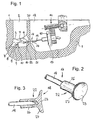
- an electromechanical hearing aid transducer 13 is fixed by means of a positioning and fixing system designated as a whole by 14.
- the hearing aid transducer 13 may be constructed, for example, as a piezo transducer for the vibratory stimulation of the ossicular chain, in particular in the manner known from US Pat. No. 5,277,694, and is part of an at least partially implantable and preferably fully implantable hearing aid, such as a hearing aid of the type known from HNO 1997 Vol. 45, 749-774.
- Fig. 1 For the mechanical coupling of a mechanical oscillations excitable, in Fig. 1 only schematically indicated output side transducer portion 15 of the hearing aid 13 to a preselected Ankoppelstelle 16 on the ossicle chain 5, for example, to the "smooth" body of the anvil 7, from the mastoid side, is a biocompatible , mechanically passive coupling arrangement 17 is provided, which is connected to the actively oscillatable output-side converter part 15 and which rests in the implanted state with a remote from the hearing aid converter 13 Ankoppelende 18 at the coupling point 16. If an electrical voltage is applied to the hearing device converter 13, the coupling arrangement 17 is caused by means of the output-side converter part 15 to vibratory oscillations in the axial direction of the coupling arrangement.
- the audio signals recorded and electrically converted by an input-side converter (microphone) (not shown) on an electronic module in the hearing device directly lead to mechanical deflections of the coupling arrangement 17 after electronic amplification. These deflections correspond to the acoustic information.
- the deflections of the coupling arrangement 17 are forwarded to the ossicular chain of the middle ear or to the stapes or the oval or round window. They thus effect an audiological amplifying effect with appropriate design of the preprocessing electronic system.
- the coupling assembly 17 has in the illustrated embodiment, a mechanically fixedly connected to the output side transducer portion 15 coupling rod 19 which has the shape of a straight cylinder in the illustrated embodiment substantially along its entire length and in the implanted state of the mastoid cavity 12 by a in the the natural auditory canal (Aditus ad antrum) 21 located in the tympanic cavity 4 passes.
- To the coupling assembly 17 further includes a coupling element 22, which with the from the hearing device transducer 13 remote end of the coupling rod 19 is connected and the Ankoppelende 18 of the coupling assembly 17 forms.
- the Ankoppelende 18 has a contact surface 23 which has an adapted to the surface shape of the Ankoppelstelle 16 surface shape and such a surface finish and surface size, that it by applying the Ankoppelendes 18 to the Ankoppelstelle 16 to a dynamic train-pressure power coupling of coupling element 22 and Zielossikel (In the illustrated case the anvil 7) comes through a surface adhesion, which is sufficient for a play-free mutual connection of coupling element 22 and ossicle chain 5.
- the adhesion effect is supported by the fact that the middle ear space 4 always has 100% moisture and as a result a natural moisture film is present on the ossicles 6, 7, 9.
- the coupling element 22 is in its basic form corresponding to the Zielossikel or the locus of Zielossikels at the Ankoppelstelle 16 designed (concave, convex or plan) that it touches the ossicle without static bias or slight bias and a dynamic train-pressure power coupling caused due to the resulting adhesion.
- a desired static bias against the suspension bands of the middle ear can be generated by a suitable feed of the transducer 13 and thus the coupling rod 19 (corresponding to the double arrow 24 in Fig. 1) by means of the positioning and fixing system 14.
- Suitable positioning and fixing systems are described in US-A-5 788 711 and in the earlier EP patent application 99 122 684.6.
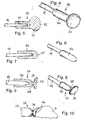
- the coupling element 22 which is shown on a larger scale in FIGS. 2 and 3, has a sleeve-shaped section 26 and a flange section 27 integrally connected thereto, which represents the coupling end 18 of the coupling arrangement 17, which is provided with a concave contact surface 23.
- the coupling element 22 is plugged with its sleeve-shaped portion 26 on the remote from the transducer 13 end of the coupling rod 19 and fixedly connected to the coupling rod, for example, crimped, welded, soldered or glued.
- a coupling element 29 is shown, which differs from the coupling element 22 only in that connects to a sleeve-shaped portion 30, a coupling end forming, spherical head 31.
- the head 31 has a larger diameter than the portion 30, and it has convexly curved contact surface 32.
- Figures 6 and 7 show a plugged onto the free end of the coupling rod 19 coupling element 34 with a substantially constant outer diameter and hemispherical Ankoppelende 35th
- the coupling element 37 illustrated in FIGS. 8, 9 and 10 is similar to the coupling element 22 of FIGS. 2 and 3. However, it additionally has a flexible intermediate element in the form of a constriction 38 at the transition point between the sleeve-shaped section 26 and the flange section 27. Depending on the material selected in the individual case for the coupling element and the dimensioning of the constriction 38, the contact surface 23 can thereby automatically adjust optimally to the coupling point 16 in the solid angle, or the coupling element can be plastically optimally plastically deformed individually by the surgeon intraoperatively.
- a coupling element 40 in the case of the coupling element of FIGS. 2 and 3, has a relatively large-area flange section 41 with a concave contact surface 23.
- the concave contact surface 23 is a complementary convex curved surface 42 of a thin coupling plate 43 opposite, which is firmly connected in the example shown with the surface of the Anboß stressess.
- the dome plate 43 may, if necessary, be anatomically adapted.
- the coupling element 40 is butt-connected to the coupling rod 19. Instead, the free coupling rod end of a to the Flange portion 41 subsequent sleeve-shaped portion corresponding to Figures 5, 7 and 9 are received.
- a coupling element 46 is provided, in which a spherical receptacle 47 adjoins the flange 23 forming the contact surface 23.
- a ball seat 47 engages a ball head 48, which is part of a fixedly connected to the coupling rod 19 ball joint part 49.
- the consisting of the ball seat 47 and the ball joint part 49 ball joint 50 allows not only an adjustment of the solid angle of the contact surface 23 with respect to the longitudinal axis of the coupling rod 19, but in addition, a rotation of the coupling rod 19 relative to the coupling element 46.
- the ball joint part fixedly connected to the coupling rod 19 may be formed as a ball seat, which cooperates with a ball head, which is part of the coupling element. Furthermore, it may be possible to dispense with a separate intermediate part between the coupling rod and the coupling element by the ball head or the ball socket is formed directly on the coupling rod.
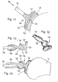
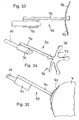
- Figures 15 to 18 show an embodiment in which between the coupling rod 19 and a coupling element 52, a flexible intermediate member 53 is inserted in the form of a separate component in order to adjust the solid angle of the contact surface 23 can.
- the coupling element 52 has a relatively large-area flange portion 54 with a connecting piece 55 which protrudes from the contact surface 23 opposite surface of the coupling element 52.
- the free end of the neck 55 is slightly convex and engages in a complementary recess 56 at one end of the intermediate member 53 a.
- the other end of the intermediate member 53 is connected to the coupling rod 19.
- a coil spring 60 which connects a flange portion 61 of the coupling element with the coupling rod 19.
- the ends of the helical spring 60 are at least non-positively connected to spring supports 63 and 64 of the coupling rod 19 and the flange portion 61.
- the spring 60 may optionally be made of a metal alloy with memory effect, in particular nitinol. Such a metal alloy can also be characterized by what is referred to as "superelasticity", that is to say that the transmitted force remains approximately the same in a certain range, even with different adjustment paths, as can be seen from the stress / strain diagram of FIG.
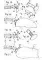
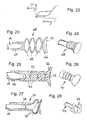
- FIGS. 23 to 28 Further possible spring elements are shown in FIGS. 23 to 28.
- a coupling element 71 is provided with a cylindrical section 72 which is inserted between a flange section 73 forming the contact surface 23 and a sleeve-shaped section 74.
- a series of circumferentially offset by 90 ° notches 75 are provided, whereby the cylindrical portion 72 are given spring characteristics.
- a sleeve-shaped section 78 merges into an arrangement of three spring clips 79 staggered in the circumferential direction.
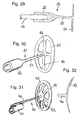
- the coupling element 81 illustrated in FIGS. 29 and 30 has a sleeve-shaped section 82 which is connected to a planar adhesion element 84 via a slender shaft 83 concentric with the section 82.
- the adhesive member 84 has a perforated structure with an outer ring 85 and a plurality of spokes 86.
- the coupling element 88 of the embodiment of FIGS. 31 and 32 is provided with a perforated concave adhesive element 89.
- the adhesion element 89 is connected via a shaft 90 with a sleeve-shaped section 91 which can be pushed onto the coupling rod and which is attached laterally to the shaft 90.
- To the adhesive member 89 in turn include an outer ring 92 and a plurality of spokes 93.
- the outer rings 85, 92 may also be broken (slotted) for a better anatomical adjustment in a manner not shown.
- an adhesion element 96 has a plurality of protruding arms 97.
- the free ends 98 of the arms 97 together form the contact surface.
- the described coupling arrangement can in principle consist of any biocompatible materials, in particular metals, metal alloys and / or plastics.
- biocompatible materials in particular metals, metal alloys and / or plastics.
- titanium, gold, silver, niobium, tantalum, platinum, platinum-iridium, or alloys of these metals, implant steel, NiTi (nitinol) or other biocompatible memory molded metals may be considered as metallic materials.
- the plastics may, above all, be silicones, polyurethanes, PTFE, FEP, polycarbonates and the like. This broad selection, in particular of plastics, must be restricted accordingly if special material properties, such as plastic deformability for individual adaptation to the target ossicle, are required.
- the total mass of the coupling arrangement should preferably be below the mass of the anvil, which is on average 25 mg.
- a lowest possible weight of the coupling arrangement also leads to the reduction of inertial forces during acceleration by external influences such as impact, vibration and the like.
Landscapes
- Health & Medical Sciences (AREA)
- General Health & Medical Sciences (AREA)
- Otolaryngology (AREA)
- Neurosurgery (AREA)
- Physics & Mathematics (AREA)
- Engineering & Computer Science (AREA)
- Acoustics & Sound (AREA)
- Signal Processing (AREA)
- Prostheses (AREA)
- Coupling Device And Connection With Printed Circuit (AREA)
Claims (17)
- Dispositif pour le couplage mécanique d'une partie transducteur (15) côté sortie, pouvant être excitée pour obtenir des vibrations mécaniques, d'un transducteur électromécanique de prothèse auditive (13) implantable à l'extérieur de la zone de l'oreille moyenne dans une cavité de mastoïde artificielle en un point de couplage (16) présélectionné sur la chaîne d'osselets, la plaque de base à étrier ou une membrane terminant la fenêtre ronde ou une fenêtre artificielle dans la cochlée, dans le vestibule ou le labyrinthe (organe d'équilibre), avec un dispositif de couplage (17) biocompatible, mécaniquement passif, qui est relié à la partie transducteur côté sortie, va dans l'état implanté de la cavité de mastoïde à la cage du tympan et s'appuie par une extrémité de couplage (18), éloignée du transducteur de prothèse auditive, sur le point de couplage, caractérisé en ce que l'extrémité de couplage (18) est formé par un élément de couplage (22, 29, 34, 37, 40, 46, 52, 59, 68, 71, 77, 81, 88, 95) avec une surface de couplage (32), qui présente une forme de surface pouvant être adaptée ou adaptée à la forme de surface du point de couplage et une qualité de surface et une grandeur de surface telles que, par le placement de l'extrémité de couplage au point de couplage, on arrive à un couplage de force de traction et de pression dynamique de l'élément de couplage et de la chaîne d'osselets par adhésion de surface qui est suffisant pour une liaison sûre et réciproque de l'élément couplage et de la chaîne d'osselets.
- Dispositif selon la revendication 1, caractérisé en ce que le dispositif de couplage (17) présente une tige de couplage (19) reliée de façon fixe à la partie transducteur (15) côté sortie, allant dans l'état implanté de la cavité de mastoïde à la cage de tympan et un élément de couplage (22, 29, 34, 37, 40, 46, 52, 59, 68, 71, 77, 81, 88, 95) qui peut être relié ou est relié à l'extrémité, opposée à la partie transducteur côté sortie, de la tige de couplage et forme l'extrémité de couplage (18) du dispositif de couplage.
- Dispositif selon la revendication 2, caractérisé en ce que la tige de couplage (19) et l'extrémité de couplage (18) sont reliées entre elles au moyen d'un élément intermédiaire (38, 53, 60, 69, 72, 79) flexible.
- Dispositif selon la revendication 3, caractérisé en ce que l'élément intermédiaire (38, 69, 72, 79) flexible est formé par l'élément de couplage (37, 68, 71, 77) même.
- Dispositif selon la revendication 4, caractérisé en ce que l'élément de couplage (37) est doté d'un rétrécissement (38) pour former l'élément intermédiaire flexible.
- Dispositif selon la revendication 3, caractérisé en ce que l'élément intermédiaire (53, 60) flexible est un composant séparé.
- Dispositif selon l'une quelconque des revendications 3 à 6, caractérisé en ce que l'élément intermédiaire flexible est conçu comme un élément de ressort (60, 69, 79).
- Dispositif selon la revendication 7, caractérisé en ce que l'élément intermédiaire (38, 53, 60, 69, 72, 79) flexible est à base d'un alliage métallique avec effet de mémoire.
- Dispositif selon la revendication 8, caractérisé en ce que l'élément intermédiaire (38, 53, 60, 69, 72, 79) flexible est fabriqué à base de nitinol.
- Dispositif selon l'une quelconque des revendications 2 à 5, caractérisé en ce que la tige de couplage (19) et l'élément de couplage (46) sont reliés entre eux au moyen d'une articulation sphérique (50).
- Dispositif selon l'une quelconque des revendications précédentes, caractérisé en ce que le dispositif de couplage (17) est conçu et/ou positionné dans l'état implanté de telle sorte que l'extrémité de couplage (18) touche la position de couplage (16) sans prétension statique.
- Dispositif selon l'une quelconque des revendications 1 à 10, caractérisé en ce que le dispositif de couplage (17) est conçu et/ou est positionné dans l'état est implanté de telle sorte que l'extrémité de couplage (18) touche le point de couplage (16) avec une légère prétension.
- Dispositif selon l'une quelconque des revendications précédentes, caractérisé en ce qu'un film d'humidité (44) est formé au moins dans l'état implanté entre l'extrémité de couplage (18) et le point de couplage (16).
- Dispositif selon l'une quelconque des revendications précédentes, caractérisé en ce que l'extrémité de couplage (18) est conçue concave avant le couplage par rapport au point de couplage (16).
- Dispositif selon l'une quelconque des revendications précédentes, caractérisé en ce que le point de couplage est formé par une plaquette de couplage (43) qui, dans l'état implanté, est reliée de façon fixe à la surface de la partie à contacter de la chaîne d'osselets, de la plaque de base à étrier ou d'une membrane terminant la fenêtre ronde ou une fenêtre artificielle.
- Dispositif selon l'une quelconque des revendications précédentes, caractérisé en ce que l'élément de couplage (81, 88) a une structure de grande surface et percée sur l'extrémité de couplage.
- Dispositif selon l'une quelconque des revendications 1 à 15, caractérisé en ce que l'élément de couplage (95) est muni sur l'extrémité de couplage de plusieurs bras (97) montés sur ressort.
Applications Claiming Priority (2)
| Application Number | Priority Date | Filing Date | Title |
|---|---|---|---|
| DE19923403A DE19923403C2 (de) | 1999-05-21 | 1999-05-21 | Vorrichtung zum mechanischen Ankoppeln eines in einer Mastoidhöhle implantierbaren elektromechanischen Hörgerätewandlers |
| DE19923403 | 1999-05-21 |
Publications (3)
| Publication Number | Publication Date |
|---|---|
| EP1054573A2 EP1054573A2 (fr) | 2000-11-22 |
| EP1054573A3 EP1054573A3 (fr) | 2006-01-04 |
| EP1054573B1 true EP1054573B1 (fr) | 2007-02-28 |
Family
ID=7908779
Family Applications (1)
| Application Number | Title | Priority Date | Filing Date |
|---|---|---|---|
| EP00105203A Expired - Lifetime EP1054573B1 (fr) | 1999-05-21 | 2000-03-13 | Dispositif pour le couplage mécanique d'un transducteur électromécanique de prothèse auditive implantable dans une cavité dans la mastoidite |
Country Status (5)
| Country | Link |
|---|---|
| US (1) | US6398717B1 (fr) |
| EP (1) | EP1054573B1 (fr) |
| AT (1) | ATE355720T1 (fr) |
| DE (2) | DE19923403C2 (fr) |
| DK (1) | DK1054573T3 (fr) |
Cited By (2)
| Publication number | Priority date | Publication date | Assignee | Title |
|---|---|---|---|---|
| US7720245B2 (en) | 2002-09-10 | 2010-05-18 | Auditory Licensing Company, Llc | Hearing aid system |
| US7751580B2 (en) | 2002-09-10 | 2010-07-06 | Auditory Licensing Company, Llc | Open ear hearing aid system |
Families Citing this family (51)
| Publication number | Priority date | Publication date | Assignee | Title |
|---|---|---|---|---|
| DE20014659U1 (de) * | 2000-08-24 | 2000-11-30 | Heinz Kurz GmbH Medizintechnik, 72144 Dußlingen | Vorrichtung zum Ankoppeln |
| WO2001028288A2 (fr) * | 2000-12-29 | 2001-04-19 | Phonak Ag | Appareil de correction auditive implante dans l'oreille |
| US20030229262A1 (en) * | 2001-11-20 | 2003-12-11 | Easter James Roy | Apparatus and method for ossicular fixation of implantable hearing aid actuator |
| US7278963B2 (en) * | 2003-01-27 | 2007-10-09 | Otologics, Llc | Implantable hearing aid transducer with advanceable actuator to facilitate coupling with the auditory system |
| US20030163021A1 (en) * | 2002-02-26 | 2003-08-28 | Miller Douglas Alan | Method and system for external assessment of hearing aids that include implanted actuators |
| DE10212726A1 (de) * | 2002-03-21 | 2003-10-02 | Armin Bernhard | Schallaufnehmer für ein implantierbares Hörgerät |
| DE20300723U1 (de) * | 2003-01-17 | 2003-03-13 | Heinz Kurz GmbH Medizintechnik, 72144 Dußlingen | Flexible Gehörknöchelchenprothese |
| US6945999B2 (en) * | 2003-01-27 | 2005-09-20 | Otologics Llc | Implantable hearing aid transducer with actuator interface |
| US7273447B2 (en) * | 2004-04-09 | 2007-09-25 | Otologics, Llc | Implantable hearing aid transducer retention apparatus |
| WO2004067061A2 (fr) * | 2003-01-27 | 2004-08-12 | Otologics Llc | Appareil permettant le raccordement de dispositifs implantables au systeme auditif |
| DE10331644B3 (de) * | 2003-07-08 | 2005-01-20 | Technische Universität Dresden | Gehörknöchelchenprothese |
| US7494477B2 (en) | 2003-09-02 | 2009-02-24 | Pulsecath B.V. | Catheter pump, catheter and fittings therefore and methods of using a catheter pump |
| US7137946B2 (en) * | 2003-12-11 | 2006-11-21 | Otologics Llc | Electrophysiological measurement method and system for positioning an implantable, hearing instrument transducer |
| US7153257B2 (en) * | 2004-04-09 | 2006-12-26 | Otologics, Llc | Implantable hearing aid transducer system |
| US7186211B2 (en) | 2004-04-09 | 2007-03-06 | Otologics, Llc | Transducer to actuator interface |
| EP1792519A4 (fr) * | 2004-09-10 | 2010-09-15 | Otologics Llc | Support d'implantation osseuse reglable |
| US7250059B2 (en) * | 2004-09-14 | 2007-07-31 | Clarity Corporation | Myringopexy type titanium prosthesis |
| AU2005312331B2 (en) * | 2004-11-30 | 2010-04-22 | Cochlear Acoustics Ltd | Implantable actuator for hearing aid applications |
| GB0500616D0 (en) * | 2005-01-13 | 2005-02-23 | Univ Dundee | Hearing implant |
| US7582052B2 (en) * | 2005-04-27 | 2009-09-01 | Otologics, Llc | Implantable hearing aid actuator positioning |
| WO2007011846A2 (fr) * | 2005-07-18 | 2007-01-25 | Soundquest, Inc. | Dispositif auditif integre dans l'oreille et ses procedes d'utilisation |
| US20070127757A2 (en) * | 2005-07-18 | 2007-06-07 | Soundquest, Inc. | Behind-The-Ear-Auditory Device |
| US20070142697A1 (en) * | 2005-12-16 | 2007-06-21 | Robert Edwin Schneider | Apparatus for connection of implantable devices to the auditory system |
| US20080004486A1 (en) * | 2006-06-14 | 2008-01-03 | Otologics, Llc | Compressive coupling of an implantable hearing aid actuator to an auditory component |
| US7792587B2 (en) * | 2006-09-12 | 2010-09-07 | Med-El Elektromedizinische Geraete Gmbh | Middle ear fixation structure |
| KR100847673B1 (ko) | 2006-10-23 | 2008-07-23 | 주성대학산학협력단 | 골도 진동자에 사용되는 에어-쿠션형 매스토이드 및매스토이드의 음향 진폭 및 임피던스 조절 방법 |
| GB0704125D0 (en) * | 2007-03-03 | 2007-04-11 | Univ Dundee | Ossicular replacement prosthesis |
| GB2449114A (en) | 2007-05-11 | 2008-11-12 | Sentient Medical Ltd | Middle ear implant with piezoelectric actuator acting on stapes footplate |
| US7722525B2 (en) * | 2007-05-24 | 2010-05-25 | Otologics, Llc | Lateral coupling of an implantable hearing aid actuator to an auditory component |
| WO2009062172A2 (fr) * | 2007-11-08 | 2009-05-14 | Otologics, Llc | Connecteur traversant pour prothèse auditive implantable |
| DE102008015115A1 (de) * | 2008-03-20 | 2009-10-01 | Heinz Kurz Gmbh Medizintechnik | Gehörknöchelchenprothese mit variablen Ankopplungsflächen |
| US20090306458A1 (en) * | 2008-03-31 | 2009-12-10 | Cochlear Limited | Direct acoustic cochlear stimulator for round window access |
| US8262729B2 (en) * | 2008-07-08 | 2012-09-11 | Enteroptyx | Dynamic ossicular prosthesis |
| USD661809S1 (en) * | 2010-01-13 | 2012-06-12 | Widex A/S | Acoustic coupler for a hearing aid |
| EP2583639B1 (fr) * | 2010-01-21 | 2014-06-25 | MED-EL Elektromedizinische Geraete GmbH | Remplacement de l'enclume ossiculaire remplacement partiel de la prothèse |
| WO2011152650A2 (fr) * | 2010-05-31 | 2011-12-08 | 주식회사 메가젠임플란트 | Dispositif de traitement de surface pour implant dentaire |
| EP2629847B1 (fr) * | 2010-10-19 | 2017-11-22 | Cochlear Limited | Interface relais de connexion d'un dispositif médical implanté à un dispositif électronique externe |
| US20120245407A1 (en) * | 2011-03-23 | 2012-09-27 | Vibrant Med-El Hearing Technology Gmbh | Line Transmission for Vibratory Actuation in Implantable Transducers |
| KR101223693B1 (ko) * | 2011-06-16 | 2013-01-21 | 경북대학교 산학협력단 | 구동력이 우수한 3코일 타입의 정원창 구동 진동체 |
| US9119010B2 (en) * | 2011-12-09 | 2015-08-25 | Sophono, Inc. | Implantable sound transmission device for magnetic hearing aid, and corresponding systems, devices and components |
| US9191760B2 (en) | 2012-06-25 | 2015-11-17 | Vibrant Med-El Hearing Technology Gmbh | Optimal pre-load for floating mass transducers |
| US10362417B2 (en) | 2012-09-28 | 2019-07-23 | Cochlear Limited | Adjustable fixation device having reduced infection |
| WO2015077786A1 (fr) * | 2013-11-25 | 2015-05-28 | Massachusetts Eye & Ear Infirmary | Capteurs piézoélectriques pour prothèses auditives |
| US10348891B2 (en) | 2015-09-06 | 2019-07-09 | Deborah M. Manchester | System for real time, remote access to and adjustment of patient hearing aid with patient in normal life environment |
| FR3046323B1 (fr) * | 2015-12-24 | 2018-02-02 | Universite D'aix Marseille | Microphone implantable pour une prothese d’oreille implantable |
| DE202016105874U1 (de) * | 2016-10-19 | 2016-11-04 | Heinz Kurz Gmbh Medizintechnik | Gehörknöchelchenprothese mit faltbarer Kopfplatte |
| DE102017115806B3 (de) * | 2017-07-13 | 2018-08-30 | Heinz Kurz Gmbh | Selbstklemmende Kopfplatte für eine Gehörknöchelchenprothese und Gehörknöchelchenprothese |
| TR201817199A2 (tr) * | 2018-11-14 | 2019-03-21 | Secaattin Guelsen | Bi̇r i̇şi̇tme protezi̇ i̇le sabi̇tleyi̇ci̇ aparat ve bu aparatin uygulama yöntemi̇ |
| CN113058156B (zh) * | 2020-05-26 | 2021-12-07 | 复旦大学 | 一种人工耳蜗的植入装置 |
| DE102021107955A1 (de) * | 2021-03-30 | 2022-10-06 | Med-El Elektromedizinische Geräte GmbH | Gehörknöchelchenprothese |
| RU2766413C1 (ru) * | 2021-04-23 | 2022-03-15 | Общество с ограниченной ответственностью "КОНМЕТ" | Имплантат в качестве протеза слуховых косточек для замещения поврежденных частей среднего уха |
Family Cites Families (21)
| Publication number | Priority date | Publication date | Assignee | Title |
|---|---|---|---|---|
| US3712962A (en) | 1971-04-05 | 1973-01-23 | J Epley | Implantable piezoelectric hearing aid |
| GB1440724A (en) | 1972-07-18 | 1976-06-23 | Fredrickson J M | Implantable electromagnetic hearing aid |
| US3882285A (en) | 1973-10-09 | 1975-05-06 | Vicon Instr Company | Implantable hearing aid and method of improving hearing |
| US4850962A (en) | 1984-12-04 | 1989-07-25 | Medical Devices Group, Inc. | Implantable hearing aid and method of improving hearing |
| US5015225A (en) | 1985-05-22 | 1991-05-14 | Xomed, Inc. | Implantable electromagnetic middle-ear bone-conduction hearing aid device |
| US5015224A (en) | 1988-10-17 | 1991-05-14 | Maniglia Anthony J | Partially implantable hearing aid device |
| US5061280A (en) | 1989-04-04 | 1991-10-29 | Microtek Medical, Inc. | Ossicular prosthesis |
| KR100229086B1 (ko) * | 1990-11-07 | 1999-11-01 | 빈센트 블루비너지 | 청각 장치를 위한 접촉 변환기 조립체 |
| DE4104359A1 (de) | 1991-02-13 | 1992-08-20 | Implex Gmbh | Ladesystem fuer implantierbare hoerhilfen und tinnitus-maskierer |
| DE4104358A1 (de) | 1991-02-13 | 1992-08-20 | Implex Gmbh | Implantierbares hoergeraet zur anregung des innenohres |
| US5624376A (en) | 1993-07-01 | 1997-04-29 | Symphonix Devices, Inc. | Implantable and external hearing systems having a floating mass transducer |
| US5554096A (en) | 1993-07-01 | 1996-09-10 | Symphonix | Implantable electromagnetic hearing transducer |
| DE19618964C2 (de) | 1996-05-10 | 1999-12-16 | Implex Hear Tech Ag | Implantierbares Positionier- und Fixiersystem für aktorische und sensorische Implantate |
| US6005955A (en) | 1996-08-07 | 1999-12-21 | St. Croix Medical, Inc. | Middle ear transducer |
| US5836863A (en) | 1996-08-07 | 1998-11-17 | St. Croix Medical, Inc. | Hearing aid transducer support |
| US5997466A (en) | 1996-08-07 | 1999-12-07 | St. Croix Medical, Inc. | Implantable hearing system having multiple transducers |
| US5707338A (en) | 1996-08-07 | 1998-01-13 | St. Croix Medical, Inc. | Stapes vibrator |
| US5762583A (en) | 1996-08-07 | 1998-06-09 | St. Croix Medical, Inc. | Piezoelectric film transducer |
| DE19738587C1 (de) * | 1997-09-03 | 1999-05-27 | Implex Gmbh | Anordnung zum Einstellen und Fixieren der Relativlage zweier Elemente eines aktiven oder passiven Hör-Implantats |
| DE19745331A1 (de) * | 1997-10-14 | 1999-04-15 | Schumann Klaus | Elektronisches Hörgerät |
| EP0936840A1 (fr) * | 1998-02-16 | 1999-08-18 | Daniel F. àWengen | Prothèse auditive implantable |
-
1999
- 1999-05-21 DE DE19923403A patent/DE19923403C2/de not_active Expired - Fee Related
-
2000
- 2000-03-13 EP EP00105203A patent/EP1054573B1/fr not_active Expired - Lifetime
- 2000-03-13 AT AT00105203T patent/ATE355720T1/de not_active IP Right Cessation
- 2000-03-13 DK DK00105203T patent/DK1054573T3/da active
- 2000-03-13 DE DE50014102T patent/DE50014102D1/de not_active Expired - Lifetime
- 2000-05-22 US US09/576,009 patent/US6398717B1/en not_active Expired - Lifetime
Cited By (3)
| Publication number | Priority date | Publication date | Assignee | Title |
|---|---|---|---|---|
| US7720245B2 (en) | 2002-09-10 | 2010-05-18 | Auditory Licensing Company, Llc | Hearing aid system |
| US7751580B2 (en) | 2002-09-10 | 2010-07-06 | Auditory Licensing Company, Llc | Open ear hearing aid system |
| US8483419B1 (en) | 2002-09-10 | 2013-07-09 | Auditory Licensing Company, Llc | Open ear hearing aid system |
Also Published As
| Publication number | Publication date |
|---|---|
| EP1054573A3 (fr) | 2006-01-04 |
| EP1054573A2 (fr) | 2000-11-22 |
| ATE355720T1 (de) | 2006-03-15 |
| DK1054573T3 (da) | 2007-06-11 |
| DE19923403A1 (de) | 2000-12-07 |
| DE19923403C2 (de) | 2002-11-14 |
| DE50014102D1 (de) | 2007-04-12 |
| US6398717B1 (en) | 2002-06-04 |
Similar Documents
| Publication | Publication Date | Title |
|---|---|---|
| EP1054573B1 (fr) | Dispositif pour le couplage mécanique d'un transducteur électromécanique de prothèse auditive implantable dans une cavité dans la mastoidite | |
| EP1073313B1 (fr) | Dispositif pour le couplage mécanique d'un vibreur à une place de couplage de la chaîne ossiculaire | |
| EP1179969B1 (fr) | Système auditif au moins partiellement implantable | |
| EP0499940B1 (fr) | Transducteur électromécanique pour appareils de correction auditive implantables | |
| EP1173044B1 (fr) | Système implantable de réhabilitation d'un trouble auditif | |
| EP1246503B1 (fr) | Système auditif entièrement implantable | |
| EP1181950B1 (fr) | Système auditif implantable comportant des moyens de mesure de la qualité d'accouplement | |
| EP1067820B1 (fr) | Dispositif pour le couplage mécanique d'un vibreur à un place de couplage du chaîne ossicullair | |
| DE19948375B4 (de) | Anordnung zum mechanischen Ankoppeln eines Treibers an eine Ankoppelstelle der Ossikelkette | |
| EP1145734B1 (fr) | Système au moins partiellement implantable de réhabilitation d'un trouble auditif | |
| DE10047388C1 (de) | Mindestens teilweise implantierbares Hörsystem | |
| DE19882589B3 (de) | Wandler mit piezoelektrischem Film | |
| DE3780245T2 (de) | Implantierbare hoerhilfe. | |
| EP1094687B1 (fr) | Dispositif pour le couplage mécanique d'un vibreur à un place de couplage du chaîne ossicullair | |
| DE10046938A1 (de) | Mindestens teilimplantierbares Hörsystem mit direkter mechanischer Stimulation eines lymphatischen Raums des Innenohres | |
| EP1018988A1 (fr) | Dispositif de polarisation pour protheses auditives implantables | |
| EP1011294A2 (fr) | Dispositif implantable pour le traitement d'oreille | |
| EP1439737B1 (fr) | Transducteur électromécanique implantable | |
| Maniglia | Implantable hearing devices: State of the art | |
| CN108886664B (zh) | 中耳联接器的预加载反馈 | |
| DE102004038078B4 (de) | Implantierbarer Hörgeräteteil | |
| DE102007059748A1 (de) | Positionierungsvorrichtung für aktive Innenohrimplantate |
Legal Events
| Date | Code | Title | Description |
|---|---|---|---|
| PUAI | Public reference made under article 153(3) epc to a published international application that has entered the european phase |
Free format text: ORIGINAL CODE: 0009012 |
|
| AK | Designated contracting states |
Kind code of ref document: A2 Designated state(s): AT BE CH CY DE DK ES FI FR GB GR IE IT LI LU MC NL PT SE |
|
| AX | Request for extension of the european patent |
Free format text: AL;LT;LV;MK;RO;SI |
|
| RAP1 | Party data changed (applicant data changed or rights of an application transferred) |
Owner name: PHONAK AG |
|
| PUAL | Search report despatched |
Free format text: ORIGINAL CODE: 0009013 |
|
| AK | Designated contracting states |
Kind code of ref document: A3 Designated state(s): AT BE CH CY DE DK ES FI FR GB GR IE IT LI LU MC NL PT SE |
|
| AX | Request for extension of the european patent |
Extension state: AL LT LV MK RO SI |
|
| RIC1 | Information provided on ipc code assigned before grant |
Ipc: H04R 25/00 20060101AFI20000905BHEP Ipc: A61F 2/18 20060101ALI20051115BHEP |
|
| 17P | Request for examination filed |
Effective date: 20060601 |
|
| AKX | Designation fees paid |
Designated state(s): AT BE CH CY DE DK ES FI FR GB GR IE IT LI LU MC NL PT SE |
|
| GRAC | Information related to communication of intention to grant a patent modified |
Free format text: ORIGINAL CODE: EPIDOSCIGR1 |
|
| GRAP | Despatch of communication of intention to grant a patent |
Free format text: ORIGINAL CODE: EPIDOSNIGR1 |
|
| GRAS | Grant fee paid |
Free format text: ORIGINAL CODE: EPIDOSNIGR3 |
|
| GRAA | (expected) grant |
Free format text: ORIGINAL CODE: 0009210 |
|
| AK | Designated contracting states |
Kind code of ref document: B1 Designated state(s): AT BE CH CY DE DK ES FI FR GB GR IE IT LI LU MC NL PT SE |
|
| PG25 | Lapsed in a contracting state [announced via postgrant information from national office to epo] |
Ref country code: FI Free format text: LAPSE BECAUSE OF FAILURE TO SUBMIT A TRANSLATION OF THE DESCRIPTION OR TO PAY THE FEE WITHIN THE PRESCRIBED TIME-LIMIT Effective date: 20070228 Ref country code: IE Free format text: LAPSE BECAUSE OF FAILURE TO SUBMIT A TRANSLATION OF THE DESCRIPTION OR TO PAY THE FEE WITHIN THE PRESCRIBED TIME-LIMIT Effective date: 20070228 Ref country code: NL Free format text: LAPSE BECAUSE OF FAILURE TO SUBMIT A TRANSLATION OF THE DESCRIPTION OR TO PAY THE FEE WITHIN THE PRESCRIBED TIME-LIMIT Effective date: 20070228 |
|
| REG | Reference to a national code |
Ref country code: GB Ref legal event code: FG4D Free format text: NOT ENGLISH |
|
| REG | Reference to a national code |
Ref country code: CH Ref legal event code: EP Ref country code: CH Ref legal event code: NV Representative=s name: TROESCH SCHEIDEGGER WERNER AG |
|
| REF | Corresponds to: |
Ref document number: 50014102 Country of ref document: DE Date of ref document: 20070412 Kind code of ref document: P |
|
| REG | Reference to a national code |
Ref country code: IE Ref legal event code: FG4D Free format text: LANGUAGE OF EP DOCUMENT: GERMAN |
|
| PG25 | Lapsed in a contracting state [announced via postgrant information from national office to epo] |
Ref country code: SE Free format text: LAPSE BECAUSE OF FAILURE TO SUBMIT A TRANSLATION OF THE DESCRIPTION OR TO PAY THE FEE WITHIN THE PRESCRIBED TIME-LIMIT Effective date: 20070531 |
|
| PG25 | Lapsed in a contracting state [announced via postgrant information from national office to epo] |
Ref country code: ES Free format text: LAPSE BECAUSE OF FAILURE TO SUBMIT A TRANSLATION OF THE DESCRIPTION OR TO PAY THE FEE WITHIN THE PRESCRIBED TIME-LIMIT Effective date: 20070608 |
|
| GBT | Gb: translation of ep patent filed (gb section 77(6)(a)/1977) |
Effective date: 20070530 |
|
| PG25 | Lapsed in a contracting state [announced via postgrant information from national office to epo] |
Ref country code: PT Free format text: LAPSE BECAUSE OF FAILURE TO SUBMIT A TRANSLATION OF THE DESCRIPTION OR TO PAY THE FEE WITHIN THE PRESCRIBED TIME-LIMIT Effective date: 20070730 |
|
| NLV1 | Nl: lapsed or annulled due to failure to fulfill the requirements of art. 29p and 29m of the patents act | ||
| REG | Reference to a national code |
Ref country code: IE Ref legal event code: FD4D |
|
| EN | Fr: translation not filed | ||
| BERE | Be: lapsed |
Owner name: PHONAK A.G. Effective date: 20070331 |
|
| PG25 | Lapsed in a contracting state [announced via postgrant information from national office to epo] |
Ref country code: BE Free format text: LAPSE BECAUSE OF NON-PAYMENT OF DUE FEES Effective date: 20070331 |
|
| PLBE | No opposition filed within time limit |
Free format text: ORIGINAL CODE: 0009261 |
|
| STAA | Information on the status of an ep patent application or granted ep patent |
Free format text: STATUS: NO OPPOSITION FILED WITHIN TIME LIMIT |
|
| PG25 | Lapsed in a contracting state [announced via postgrant information from national office to epo] |
Ref country code: MC Free format text: LAPSE BECAUSE OF NON-PAYMENT OF DUE FEES Effective date: 20070331 |
|
| 26N | No opposition filed |
Effective date: 20071129 |
|
| PG25 | Lapsed in a contracting state [announced via postgrant information from national office to epo] |
Ref country code: GR Free format text: LAPSE BECAUSE OF FAILURE TO SUBMIT A TRANSLATION OF THE DESCRIPTION OR TO PAY THE FEE WITHIN THE PRESCRIBED TIME-LIMIT Effective date: 20070529 Ref country code: IT Free format text: LAPSE BECAUSE OF FAILURE TO SUBMIT A TRANSLATION OF THE DESCRIPTION OR TO PAY THE FEE WITHIN THE PRESCRIBED TIME-LIMIT Effective date: 20070228 Ref country code: FR Free format text: LAPSE BECAUSE OF FAILURE TO SUBMIT A TRANSLATION OF THE DESCRIPTION OR TO PAY THE FEE WITHIN THE PRESCRIBED TIME-LIMIT Effective date: 20071019 |
|
| PG25 | Lapsed in a contracting state [announced via postgrant information from national office to epo] |
Ref country code: AT Free format text: LAPSE BECAUSE OF NON-PAYMENT OF DUE FEES Effective date: 20070313 |
|
| PG25 | Lapsed in a contracting state [announced via postgrant information from national office to epo] |
Ref country code: FR Free format text: LAPSE BECAUSE OF FAILURE TO SUBMIT A TRANSLATION OF THE DESCRIPTION OR TO PAY THE FEE WITHIN THE PRESCRIBED TIME-LIMIT Effective date: 20070228 |
|
| PG25 | Lapsed in a contracting state [announced via postgrant information from national office to epo] |
Ref country code: CY Free format text: LAPSE BECAUSE OF FAILURE TO SUBMIT A TRANSLATION OF THE DESCRIPTION OR TO PAY THE FEE WITHIN THE PRESCRIBED TIME-LIMIT Effective date: 20070228 |
|
| PG25 | Lapsed in a contracting state [announced via postgrant information from national office to epo] |
Ref country code: LU Free format text: LAPSE BECAUSE OF NON-PAYMENT OF DUE FEES Effective date: 20070313 |
|
| PGFP | Annual fee paid to national office [announced via postgrant information from national office to epo] |
Ref country code: DK Payment date: 20110303 Year of fee payment: 12 |
|
| PGFP | Annual fee paid to national office [announced via postgrant information from national office to epo] |
Ref country code: CH Payment date: 20110303 Year of fee payment: 12 |
|
| PGFP | Annual fee paid to national office [announced via postgrant information from national office to epo] |
Ref country code: GB Payment date: 20110302 Year of fee payment: 12 |
|
| REG | Reference to a national code |
Ref country code: CH Ref legal event code: PL |
|
| REG | Reference to a national code |
Ref country code: DK Ref legal event code: EBP |
|
| GBPC | Gb: european patent ceased through non-payment of renewal fee |
Effective date: 20120313 |
|
| PG25 | Lapsed in a contracting state [announced via postgrant information from national office to epo] |
Ref country code: CH Free format text: LAPSE BECAUSE OF NON-PAYMENT OF DUE FEES Effective date: 20120331 Ref country code: LI Free format text: LAPSE BECAUSE OF NON-PAYMENT OF DUE FEES Effective date: 20120331 Ref country code: GB Free format text: LAPSE BECAUSE OF NON-PAYMENT OF DUE FEES Effective date: 20120313 |
|
| PG25 | Lapsed in a contracting state [announced via postgrant information from national office to epo] |
Ref country code: DK Free format text: LAPSE BECAUSE OF NON-PAYMENT OF DUE FEES Effective date: 20120331 |
|
| PGFP | Annual fee paid to national office [announced via postgrant information from national office to epo] |
Ref country code: DE Payment date: 20130331 Year of fee payment: 14 |
|
| REG | Reference to a national code |
Ref country code: DE Ref legal event code: R082 Ref document number: 50014102 Country of ref document: DE Representative=s name: GRUENECKER, KINKELDEY, STOCKMAIR & SCHWANHAEUS, DE |
|
| REG | Reference to a national code |
Ref country code: DE Ref legal event code: R119 Ref document number: 50014102 Country of ref document: DE |
|
| REG | Reference to a national code |
Ref country code: DE Ref legal event code: R119 Ref document number: 50014102 Country of ref document: DE Effective date: 20141001 |
|
| PG25 | Lapsed in a contracting state [announced via postgrant information from national office to epo] |
Ref country code: DE Free format text: LAPSE BECAUSE OF NON-PAYMENT OF DUE FEES Effective date: 20141001 |