EP0984814B1 - Pompe munie d'un mecanisme empechant un ecoulement denoye - Google Patents
Pompe munie d'un mecanisme empechant un ecoulement denoye Download PDFInfo
- Publication number
- EP0984814B1 EP0984814B1 EP98928948A EP98928948A EP0984814B1 EP 0984814 B1 EP0984814 B1 EP 0984814B1 EP 98928948 A EP98928948 A EP 98928948A EP 98928948 A EP98928948 A EP 98928948A EP 0984814 B1 EP0984814 B1 EP 0984814B1
- Authority
- EP
- European Patent Office
- Prior art keywords
- pump
- carrier
- tubing
- clamp
- door
- Prior art date
- Legal status (The legal status is an assumption and is not a legal conclusion. Google has not performed a legal analysis and makes no representation as to the accuracy of the status listed.)
- Expired - Lifetime
Links
- 230000002572 peristaltic effect Effects 0.000 claims abstract description 13
- 230000000694 effects Effects 0.000 claims abstract description 3
- 239000012530 fluid Substances 0.000 claims description 16
- 238000013461 design Methods 0.000 description 12
- 238000001802 infusion Methods 0.000 description 11
- 230000007246 mechanism Effects 0.000 description 10
- 238000001990 intravenous administration Methods 0.000 description 8
- 210000004027 cell Anatomy 0.000 description 7
- 238000010348 incorporation Methods 0.000 description 3
- 238000000034 method Methods 0.000 description 3
- 238000005086 pumping Methods 0.000 description 3
- 230000009471 action Effects 0.000 description 2
- 230000008901 benefit Effects 0.000 description 2
- 239000008280 blood Substances 0.000 description 2
- 210000003743 erythrocyte Anatomy 0.000 description 2
- 238000003780 insertion Methods 0.000 description 2
- 230000037431 insertion Effects 0.000 description 2
- 238000004519 manufacturing process Methods 0.000 description 2
- 230000008569 process Effects 0.000 description 2
- 210000003462 vein Anatomy 0.000 description 2
- XFVULMDJZXYMSG-ZIYNGMLESA-N 5-amino-1-(5-phospho-D-ribosyl)imidazole-4-carboxylic acid Chemical compound NC1=C(C(O)=O)N=CN1[C@H]1[C@H](O)[C@H](O)[C@@H](COP(O)(O)=O)O1 XFVULMDJZXYMSG-ZIYNGMLESA-N 0.000 description 1
- 230000001580 bacterial effect Effects 0.000 description 1
- 230000009286 beneficial effect Effects 0.000 description 1
- 210000004369 blood Anatomy 0.000 description 1
- 210000000601 blood cell Anatomy 0.000 description 1
- 210000004905 finger nail Anatomy 0.000 description 1
- 238000002347 injection Methods 0.000 description 1
- 239000007924 injection Substances 0.000 description 1
- 239000007788 liquid Substances 0.000 description 1
- 239000004973 liquid crystal related substance Substances 0.000 description 1
- 239000002184 metal Substances 0.000 description 1
- 238000012986 modification Methods 0.000 description 1
- 230000004048 modification Effects 0.000 description 1
- 230000001681 protective effect Effects 0.000 description 1
- 238000010926 purge Methods 0.000 description 1
- 230000000717 retained effect Effects 0.000 description 1
- 238000010079 rubber tapping Methods 0.000 description 1
- 229920001169 thermoplastic Polymers 0.000 description 1
- 239000004416 thermosoftening plastic Substances 0.000 description 1
Images






Classifications
-
- A—HUMAN NECESSITIES
- A61—MEDICAL OR VETERINARY SCIENCE; HYGIENE
- A61M—DEVICES FOR INTRODUCING MEDIA INTO, OR ONTO, THE BODY; DEVICES FOR TRANSDUCING BODY MEDIA OR FOR TAKING MEDIA FROM THE BODY; DEVICES FOR PRODUCING OR ENDING SLEEP OR STUPOR
- A61M5/00—Devices for bringing media into the body in a subcutaneous, intra-vascular or intramuscular way; Accessories therefor, e.g. filling or cleaning devices, arm-rests
- A61M5/14—Infusion devices, e.g. infusing by gravity; Blood infusion; Accessories therefor
- A61M5/142—Pressure infusion, e.g. using pumps
-
- A—HUMAN NECESSITIES
- A61—MEDICAL OR VETERINARY SCIENCE; HYGIENE
- A61M—DEVICES FOR INTRODUCING MEDIA INTO, OR ONTO, THE BODY; DEVICES FOR TRANSDUCING BODY MEDIA OR FOR TAKING MEDIA FROM THE BODY; DEVICES FOR PRODUCING OR ENDING SLEEP OR STUPOR
- A61M39/00—Tubes, tube connectors, tube couplings, valves, access sites or the like, specially adapted for medical use
- A61M39/22—Valves or arrangement of valves
- A61M39/28—Clamping means for squeezing flexible tubes, e.g. roller clamps
- A61M39/281—Automatic tube cut-off devices, e.g. squeezing tube on detection of air
-
- A—HUMAN NECESSITIES
- A61—MEDICAL OR VETERINARY SCIENCE; HYGIENE
- A61M—DEVICES FOR INTRODUCING MEDIA INTO, OR ONTO, THE BODY; DEVICES FOR TRANSDUCING BODY MEDIA OR FOR TAKING MEDIA FROM THE BODY; DEVICES FOR PRODUCING OR ENDING SLEEP OR STUPOR
- A61M39/00—Tubes, tube connectors, tube couplings, valves, access sites or the like, specially adapted for medical use
- A61M39/22—Valves or arrangement of valves
- A61M39/28—Clamping means for squeezing flexible tubes, e.g. roller clamps
- A61M39/286—Wedge clamps, e.g. roller clamps with inclined guides
- A61M39/287—Wedge formed by a slot having varying width, e.g. slide clamps
-
- A—HUMAN NECESSITIES
- A61—MEDICAL OR VETERINARY SCIENCE; HYGIENE
- A61M—DEVICES FOR INTRODUCING MEDIA INTO, OR ONTO, THE BODY; DEVICES FOR TRANSDUCING BODY MEDIA OR FOR TAKING MEDIA FROM THE BODY; DEVICES FOR PRODUCING OR ENDING SLEEP OR STUPOR
- A61M5/00—Devices for bringing media into the body in a subcutaneous, intra-vascular or intramuscular way; Accessories therefor, e.g. filling or cleaning devices, arm-rests
- A61M5/14—Infusion devices, e.g. infusing by gravity; Blood infusion; Accessories therefor
- A61M5/142—Pressure infusion, e.g. using pumps
- A61M5/14212—Pumping with an aspiration and an expulsion action
- A61M5/14228—Pumping with an aspiration and an expulsion action with linear peristaltic action, i.e. comprising at least three pressurising members or a helical member
Definitions
- This invention relates to a liquid delivery system and is especially suitable for use as part of an infusion pump system designed to deliver parenteral and enteral fluids, as well as whole blood or red blood cell components, using a wide variety of standard intravenous administration sets and fluid containers.
- One conventional type of infusion pump system employs a peristaltic pump in conjunction with an intravenous administration set.
- the set consists of flexible thermoplastic tubing through which fluid flows from a suspended container, such as a flexible bag or rigid bottle, to a patient's indwelling vein access device, such as a needle or cannula inserted into the patient.
- a length of the administration set tubing between the fluid container and the patient is mounted in the peristaltic pump which sequentially squeezes adjacent sections of the tubing so as to pump the fluid via a peristaltic action along the tubing into the patient. Examples of such conventional type of infusion a system are presented by the patent applications WO-A-9305829 and US-A-5482446.
- such an improved system could be employed with a relatively simple clamp mounted on the tubing.
- such an improved system should be capable of functioning with a simple or standard slide clamp on standard intravenous administration set tubing and should not require the use of a more complicated, multi-piece clamping mechanism on such tubing.
- a standard intravenous administration set is disposable and is provided to medical personnel in a sterile, protective package. It would be desirable to provide such an administration set with a tubing clamp that can be automatically operated by the improved pump system and that has a relatively simple design which employs a relatively small size and shape facilitating low cost manufacture, which is easy to sterilize, and which is convenient to package, store, and handle.
- an improved infusion pump system should accommodate relatively simple assembly procedures.
- Such a simple tubing loading process can be easier to learn and is less likely to be improperly executed than less intuitive processes.
- the present invention provides an improved infusion pump system which can accommodate designs that have the above-discussed benefits and features, which is convenient to use, and which is cost-effective with respect to its manufacture and operation.
- the system is easily operated and can be used with a wide variety of standard administration sets and fluid containers.
- the system is designed to meet the growing demand for hospital-wide standardization, as well as alternate-site, in-home healthcare standardization.
- the present invention relates to a pump, according to claim 1.
- the clamp has an open condition in which the tubing is free to return to an open configuration.
- the tubing, with the clamp disposed thereon, can be loaded into the receiving path of the pump from the inlet end to the outlet end.
- a pump incorporating features of this invention is described in one normal (upright) orientation, and terms such as upper, lower, horizontal, etc., are used with reference to this orientation. It will be understood, however, that the pump of this invention may be stored, transported, and sold in an orientation other than the orientation described.
- the improved system of the present invention accommodates delivery of a fluid to a patient with a variety of standard, intravenous administration sets, one of which is illustrated in FIG. 1 and is designated generally therein by the reference numeral 40.
- the administration set 40 is typically employed to deliver parenteral fluids, enteral fluids, whole blood, red blood cell components, and the like from a fluid container, such as a bottle or such as a flexible bag 42 which is shown in FIG. 2 supported on an intravenous administration stand 44.
- a portion of the administration set 40 is engaged by a peristaltic pump 50, and a distal portion of the administration set 40 downstream of the pump 50 can be connected to a patient's indwelling vein access device, such as a needle or cannula (not illustrated) which is inserted into the patient.
- a peristaltic pump 50 a distal portion of the administration set 40 downstream of the pump 50 can be connected to a patient's indwelling vein access device, such as a needle or cannula (not illustrated) which is inserted into the patient.
- the container 42 may be of any suitable conventional or special design. The detailed design and specific structure of the container 42 form no part of the present invention.
- the administration set 40 may be of any appropriate conventional or special design.
- the set 40 illustrated in FIG. 1 is a primary, vented, intravenous set sold in the U.S.A. under the designation No. 1881 by Abbott Laboratories, 100 Abbott Park Road, Abbott Park, Illinois 60064-3500, U.S.A.
- the administration set 40 has a proximal end defined by a hollow, piercing pin 46 projecting from a conventional bacterial retentive air filter 48 at the upper end of a drip chamber 52.
- a length of hollow, flexible tubing 54 extends from the bottom of the drip chamber 52 through a roller clamp 56 of the type sold by Abbott Laboratories under the designation CAIR.
- a slide clamp 60 Disposed on the tubing 54 downstream of the roller clamp 56 is a slide clamp 60 of the type sold by Abbott Laboratories under the designation DUO SLIDE.
- the DUO SLIDE clamp 60 is described in more detail hereinafter.
- a conventional Y-injection site 62 is provided on the tubing 54 downstream of the slide clamp 60.
- the distal end of the tubing 54 is provided with a conventional male adaptor 64.
- the adaptor 64 is designed to be attached to a venipuncture device.
- the administration set components may be of any suitable special or conventional design, the details of which form no part of the present invention except that some features of a preferred embodiment of the invention are designed to accommodate, and cooperate with, conventional, flexible tubing 54 and with the slide clamp 60 having the structure as embodied in the above-identified DUO SLIDE clamp 60.
- the structure of DUO SLIDE clamp 60 is described in more detail hereinafter.
- the pump 50 includes a housing 70 and a rearwardly projecting mounting clamp 72 by which the pump 50 can be mounted to the stand 44.
- the clamp 72 includes a manually operable knob 73.
- a convenient carrying handle 74 projects upwardly from the top of the housing 70. Electric power is provided through the rear of the pump via a power cord 71.
- the pump 50 has a front panel 76 containing a liquid crystal display screen device 78 and a key pad 80.
- a front door 90 on which is mounted a door handle 94.
- the door 90 can be opened about 90° by initially pivoting the handle 94 from a substantially vertical orientation (as shown in FIG. 2) to a substantially horizontal orientation (as shown in FIG. 3) to unlatch the door 90 from the housing 70, and then swinging the door 90 outwardly.
- the open pump 50 is shown with the tubing 54 removed so as to better illustrate the details of the pump structure.
- the housing 70 includes an exterior covering or shell 96 which is partly shown in phantom by dashed lines so as to reveal interior details.
- the door 90 has an exterior cover or shell 98 which is shown partly in phantom by dashed lines to better illustrate interior details.
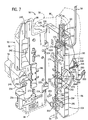
- the open face of the pump housing 70 defines a receiving path 100 for receiving the administration set tubing 54 which is shown loaded in the pump housing 70 in FIG. 7.
- the receiving path 100 is defined along a generally planar, front, inside face of the open pump housing 70.
- the pump 50 includes a block or chassis 104 (FIGS. 3-7) which may be characterized as generally defining a part of the housing 70 to which other pump components are mounted.
- the chassis 104 includes various cavities and apertures for receiving such other components which are mounted to the chassis or which coact with the chassis 104 as described in detail hereinafter.
- the receiving path 100 in the upper right-hand corner of the chassis 104 is oriented generally horizontally and opens outwardly to the right-hand side of the pump 50 through the exterior shell 96.
- the exterior shell 96 thus defines an inlet portion of the receiving path 100, and the exterior shell 96 may be characterized as also generally forming part of the pump housing 70.
- the chassis 104 is illustrated separately in FIGS. 28, 29, and 30.
- the upper right-hand corner of the chassis 104 defines a vertically oriented slot 106.
- the chassis 104 defines upwardly projecting posts 108 to which are mounted an insert block or skirt 110.
- the skirt 110 is shown separately in FIGS. 26, 27.
- the skirt 110 defines a pair of receiving apertures 112. Each aperture 112 receives one of the chassis posts 108 as shown in FIG. 28A.
- the skirt 110 can be further secured to the chassis 104 with screws (not illustrated) through screw-receiving bores 113 (FIGS. 26 and 27).
- the front of the skirt 110 defines a vertical groove 114 which communicates with the horizontal portion of the tubing receiving path 100 as can be seen in FIGS. 3, 4, 5, 9, and 28A.
- the upper, front portion of the skirt 110 defines an inwardly extending notch 118 on either side of the vertical groove 114, and the notch 118 defines a part of the receiving path 100 in the face of the pump.
- the bottom of the notch 118 at the front of the skirt 110 is defined by a pair of spaced-apart support ledges 120 which define between them a continuation of the vertical groove 114 (FIG. 5).
- the top surfaces of the ledges 120 form bottom portions of the tubing receiving path 100 on either side of the vertical groove 114.
- the vertical groove 114 extends upwardly into the housing 70 above the skirt 110 as illustrated in FIGS. 3, 4, 5, and 9.
- the chassis slot 106 below the skirt ledges 120 is relatively wide.
- the slot 106 is adapted to receive a carrier means for holding a tubing clamp.
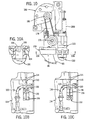
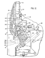
- the carrier means includes a slide clamp carrier 130 which holds the slide clamp 60 and which is adapted to move between (1) an elevated or raised position as shown in FIGS. 7, 7A, and 10C, and (2) a lowered position as shown in FIGS. 7B, 10B, and 11.
- the slide clamp 60 and tubing 54 are omitted to better illustrate details of the carrier and other components of the housing 70.
- the mechanisms for effecting movement of the carrier 130 between the upper, elevated position (shown in FIGS. 3, 4, 5, 7, 7A, and 10C) and the lowered position (illustrated in FIGS. 7B, 10B, 11, and 12) are described in detail hereinafter.
- the carrier 130 is adapted to receive and hold the slide clamp 60 in a generally vertical orientation as illustrated in FIGS. 5 and 7.
- the slide clamp 60 has a lower end defined by a laterally extending foot 134 (FIG. 5). Projecting upwardly from the foot 134 is an elongate, four-sided frame 138 surrounding a slightly thinner, generally planar, web 140.
- the web 140 defines an elongate aperture 142 having a lower, narrow portion 144 and an upper, wide portion 146.
- the clamp 60 Prior to the tubing 54 and slide clamp 60 being inserted into the pump 50, the clamp 60 is initially disposed on the tubing 54 in an orientation wherein the tubing 54 is located in the narrow portion 144 of the clamp aperture 142 so as to be squeezed into a closed configuration occluding flow therethrough (FIG. 5).
- the slide clamp 60 is adapted to accommodate subsequent movement downwardly (in the direction of the arrow 148 in FIG. 5) relative to the tubing 54, after the clamp 60 is inserted into the carrier 130.
- the downward movement is generally perpendicular to the longitudinal axis of that portion of the tubing 54 adjacent the clamp 60 so as to position the wide portion 146 of the clamp aperture 142 about the tubing 54 (FIG. 7B).
- Movement of the carrier 130 downwardly (in the direction of the arrow 148 as shown in FIG. 7B) from the elevated position (illustrated in FIGS. 5 and 7A) to the lowered position (illustrated in FIG. 7B) carries the slide clamp 60 downwardly relative to the tubing 54 which is held in the tubing receiving path on the ledges 120 above the carrier 130.
- the mechanisms for moving the clamp 60 in the carrier 130 downwardly are described in detail hereinafter.
- the carrier 130 has a configuration adapted to permit convenient insertion of the clamp 60 into the carrier 130.
- the carrier 130 includes a front portion 152 (FIGS. 13-18) which projects beyond the front face of the housing chassis 104 as shown in FIGS. 3 and 7.
- the front portion 152 is wider than the chassis slot 106 (FIG. 10B).
- the carrier 130 includes a reduced width, intermediate portion 156 (FIGS. 13-15, 17, and 18).
- the reduced width, intermediate portion 156 extends through the chassis slot 106.
- the carrier 130 includes a wider, rear portion 160.
- the wider, rear portion 160 is disposed along the rear, vertical surface of the chassis 104 along the chassis slot 106.
- the carrier 130 is initially mounted in the chassis slot 106 during assembly of the pump components prior to mounting the skirt 110 over the top of the chassis slot 106 as shown in FIG. 28A.
- the carrier 130 is adapted to reciprocate vertically within the chassis slot 106.
- the bottom, front edge of the carrier rear portion 160 includes a bridging rib 153 (FIGS. 11, 13, 14, 17, and 18) and a slot 155 (FIGS. 15 and 17) behind the bridging rib 153.
- the carrier 130 defines a first slot 161 (FIGS. 13 and 16) extending through the front portion 152, through reduced width intermediate portion 156, and partway through the rear portion 160 as can be seen in FIG. 17.
- the first slot 161 has a configuration adapted to receive the bottom end of the slide clamp 60, including the outwardly projecting foot 134 (FIG. 5).
- the bottom of the carrier slot 161 in the carrier rear portion 160 communicates with the top of the rear portion slot 155 as shown in FIG. 17.
- the carrier 130 has a second slot 162 which extends from, and which is generally normal to, the first slot 161.
- the second slot 162 is adapted to receive the vertical, upwardly extending portion of the slide clamp 60 which projects above the foot 134 when the slide clamp 60, along with the tubing 54 disposed therein, is inserted into the carrier 130 (in the direction of the arrow 166 (FIG. 5)).
- The. carrier 130 includes detents 162A and 162B (FIGS. 13 and 16) along the surface that defines the second slot 162. These detents 162A and 162B are used to grip the bottom portion of the frame 138 of the slide clamp 60 when the slide clamp 60 is inserted into the carrier 130 as shown in FIG. 7.
- the carrier vertical slot 162 is aligned in registry with the vertical groove 114 defined by the chassis skirt 110 and by the upper portion of the housing 70 as shown in FIG. 5.
- the chassis 104 includes pairs of opposed tabs 170 (FIG. 5) which project slightly into the channel of the receiving path 100 so as to grip the tubing 54 (FIG. 7) by effecting a small, local deformation of the tubing adjacent the tabs 170.
- the tabs 170 are preferably separately molded insert pieces which are mounted in appropriate receiving cavities within the chassis 104. A number of such pairs of confronting tabs 170 are provided along the receiving path 100 as shown in FIG. 4.
- a peristaltic pump head 174 is disposed along the vertical portion of the tubing receiving path 100 as shown in FIGS. 3, 4, and 7.
- the peristaltic pump head 174 may have any suitable conventional or special configuration.
- the peristaltic pump head 174 typically comprises a plurality of keys, such as keys 174A-174H, which are sequentially engaged and moved outwardly against the tubing by cam sections on a crank shaft 176 (FIG. 10) which is vertically disposed behind the keys within the pump housing 70.
- the crank shaft 176 is rotated by a timing belt driven from a shaft 180 of a stepping motor 182 (FIG. 10).
- a platen 186 is mounted in the door 90 and confronts the tubing 54 adjacent the pump head 174 when the door 90 is closed.
- Each pump head key 174A-174H forces the tubing 54 against the platen 186 (FIG. 3) on the closed door 90.
- the platen 186 is biased toward the pump head 174 by a spring (not visible) acting between the door and the platen 186.
- the next, adjacent downstream key is moved outwardly to force the fluid contained within the tube further downstream in the tubing 54 in a peristaltic action.
- the peristaltic pumping system including the above-discussed peristaltic pump system elements 174A-174H, 176, 178, 180, 182, and 186, may be of any suitable conventional or special design.
- the tubing 54 extends below the pump head 174 within the channel defining the tubing receiving path 100.
- the tubing 54 extends through an anti-flood clamp 190 near the bottom of the pump.
- the anti-flood clamp 190 includes an engaging rib 192 and a laterally extending finger press pad 194 (FIG. 6).
- the tubing 54 is normally loaded between the anvil 196 and the engaging rib 192 as shown in FIG. 7.
- a portion of the anti-flood clamp 190 extends behind the chassis 104 and includes a spring-biased, over-center toggle spring latch mechanism (not visible in the figures). Normally, when the pump door 90 is open, the anti-flood clamp rib 192 is biased to the closed position (illustrated by solid lines in FIGS. 3 and 7, and shown in phantom by dashed lines in FIG. 6).
- the finger press pad 194 In order to load the tubing 54 into the tubing receiving path 100 between the anvil 196 and the tubing engaging rib 192, the finger press pad 194 is pressed rearwardly toward the chassis 104 (in the direction of the arrow 198 as shown in FIG. 6). When the finger press pad 194 is pushed rearwardly to the point where it is substantially parallel to, and adjacent, the surface of the chassis 104, the over-center toggle spring latch mechanism behind the chassis 104 holds the anti-flood clamp 190 in the open position--even after the finger is removed from the finger press pad 194. This establishes clearance between the engaging rib 192 and the anvil 196 to accommodate positioning of the tubing 54 between the rib 192 and the anvil 196.
- the anti-flood clamp 190 described above may be of any suitable special or conventional design.
- the pump 50 may include an air sensor assembly, such as the air sensor assembly 210 below the anti-flood clamp 190 as illustrated in FIGS. 3, 4, and 7.
- the air sensor assembly 210 may be of any suitable special or conventional design for sensing the presence of air bubbles within the tubing 54.
- the sensor assembly 210 includes a piezoelectric sensor around a slot that defines part of the tubing receiving path 100.
- the pump 50 may include other sensors, switches, alarms, etc., as may be suitable or desired, but such other elements form no part of the present invention.
- the inside surface of the door 90 may include a plurality of projections 172 which align with the channel defining the tubing receiving path 100 when the door 90 is closed and which function to push the tubing 54 into the channel defining the receiving path 100.
- the tubing 54 can be easily loaded into the above-described tubing receiving path 100 in the pump 50.
- the container 42 (FIG. 2) is connected to the tubing 54.
- the roller clamp 56 Prior to connecting the tubing 54 to the container 42, the roller clamp 56 (FIG. 1) is first closed to occlude flow through the tubing 54. Then the outlet on the container 42 (FIG. 2) is exposed.
- the administration set piercing pin 46 (FIG. 1) is then inserted into the outlet of the container 42 with a twisting motion.
- the container 42 is then suspended from the stand 44, and the drip chamber 52 (FIG. 1) is filled to the score mark.
- the administration set 40 is primed. With the pump 50 located below the container 42, the roller clamp 56 is opened to expel air from the administration set tubing 54 while the slide clamp 60 located on the tubing is in an open condition so as not to occlude the tubing. The roller clamp 56 is then closed. The male adapter 64 at the distal end of the administration set tubing 54 can then be attached to a venipuncture device. If the venipuncture device is not indwelling, then the device must primed prior to making the venipuncture.
- Air is dislodged from the back check valve in the Y-site 62 by inverting and tapping it sharply while fluid is flowing.
- the operator Prior to loading the tubing 54 into the pump 50, the operator should verify that the roller clamp 56 is between the container 42 and the slide clamp 60. The operator should also verify that the roller clamp 56 is closed and confirm that there is no flow in the drip chamber 52. Next, the slide clamp 60 is closed by pushing the clamp 60 so that the tubing 54 is squeezed closed in the narrow portion 144 of the clamp aperture.
- the pump door 90 is opened by lifting the door handle 94.
- the anti-flood clamp 190 is then opened by pushing the finger press pad 194 (in the direction of the arrow 198 as shown in FIG. 6).
- the clamp 190 will remain open after the operator's finger is removed owing to the action of the over-center toggle spring mechanism with the clamp 190 as described above.
- the administration set tubing 54 is then positioned along the open face of the pump 50.
- the slide clamp 60 is aligned with the carrier slots 161 and 162 as illustrated in FIG. 5.
- the slide clamp 60, along with the closed tubing 54 disposed therein, is moved inwardly (in the direction of arrow 166 as shown in FIG. 5) so as to position the slide clamp 60 within the carrier slots 161 and 162 and within the housing vertical groove 114. This results in the portion of the tubing 54 adjacent the slide clamp 60 being received within the channel defined in the tubing receiving path 100 above the carrier 130.
- the tubing 54 is pressed into the channel defining the receiving path 100 with the pad of a finger tip while avoiding contacting the tubing with sharp objects, such as finger nails.
- the door 90 is then closed over the loaded tubing 54, and the handle 94 is latched by pushing it downwardly to the fully closed position illustrated in FIGS. 1 and 11.
- the roller clamp 56 above the pump 50 should be opened, and the lack of flow into the drip chamber 52 should be confirmed.
- the tubing receiving path is defined substantially in a plane along the housing 70 (which housing 70 includes the chassis 104 and the top skirt 110 that define the channel of the tubing receiving path).
- the plane in which the loaded tubing 54 lies is generally vertical when the pump is in the normal operating orientation.
- the clamp carrier 130 is movable between the elevated position (FIGS. 7, 7A, and 10C) and the lowered position (FIGS. 7B, 9 and 10B) in a direction that is parallel to the plane defined by the tubing receiving path.
- the pump 50 is adapted to be disposed in a normal operating orientation, as shown in FIGS. 3, 4, and 7, wherein the pump has (1) a middle portion that includes the pump head 174, (2) an upper portion that extends above the pump head and that includes the carrier 130, and (3) a lower portion that extends below the pump head 174 and that can include the anti-flood clamp 190 (if provided) and the air sensor 210 (if provided)).
- the tubing receiving path is oriented substantially in a plane which is generally vertical when the pump is in the normal operating orientation. Further, the portion of the receiving path (and tubing) along the pump head 174 lies generally in a straight line.
- the door 90 is preferably mounted on a generally vertical axis for pivoting between the open and closed positions.
- the pivot axis of the door 90 is parallel to the portion of the tubing receiving path defined along the face of the pump head 174 and is also parallel to the direction of the movement of the carrier 130 between the elevated position (FIGS. 7, 7A, and 10C) and the lowered position (FIGS. 7B, 9 and 10B).
- the door pivot axis is defined in the chassis 104, as shown in FIG. 28, by a pair of door pin-receiving projections 220.
- the door 90 defines two slots 224 for each receiving one of the chassis projections 220.
- Each of the chassis projections 220 defines a pin-receiving bore 226, and the bores 226 are aligned with bores in the door 90, such as an upper bore 228 visible in FIG. 7.
- Pins, such as the upper pin 230 visible in FIG. 7, are disposed in the bores in the door 90 and chassis projections 220 for providing a connection accommodating pivoting movement of the door 90.
- the inside of the door 90 includes an upper groove 240 (FIGS. 3 and 7) and a cavity or recess 242 (FIGS. 3 and 7) for receiving the outwardly projecting portions of the slide clamp 60 and carrier 130, respectively, when the door 90 is closed.
- the door handle 94 includes a bore 244 as shown in FIG. 31 for receiving a pin 246 (FIGS. 7 and 12) pivotally mounting the handle 94 to the door 90 for rotation between the open position (FIG. 7) and the closed position (FIG. 2).
- the handle 94 includes an arcuate latch slot 250 (FIG. 31) and an exterior camming surface 254 (FIGS. 31 and 32).
- the housing chassis 104 defines a recessed latch region 260 for receiving the curved camming surface 254 of the door handle 94.
- a boss 262 Projecting outwardly from the edge of the chassis 104 adjacent the latch region 260 is a boss 262 (FIG. 7).
- the boss 262 is a separate metal insert which is mounted in a receiving cavity 264 (FIG. 28) in the chassis 104.
- a latch roller 268 is disposed on a pin 270 mounted in the boss 262.
- the latch pin 270 and roller 268 are received in the arcuate slot 250 of the handle 94 as shown in FIG. 8A.
- the handle latch slot 250 slides along the roller 268 until the handle 94 is in the fully closed orientation as shown in FIGS. 8B, 11, and 12.
- the resiliency of the system (especially as may be provided by the spring-biased platen 186 in the door 90) creates an over-center toggle latch action holding the door handle 94 in the fully closed position to maintain the door 90 latched closed.
- the carrier 130 (FIG. 7) has previously been described as being movable between an elevated position (FIGS. 7, 7A, and 10B) and a lowered position (FIGS. 7B, 9, and 10C).
- the movement of the door handle 94 to the closed, latched position (illustrated in FIGS. 2, 9, 8B, and 11), effects movement of the carrier 130 between the elevated and lowered positions by.a novel linkage mechanism which is next described.
- the exterior camming surface 254 on the door handle 94 is designed to engage a cam follower element or crank 280 (FIGS. 7, 8B, 11, 19, and 20).
- the crank 280 defines a cam follower surface 282. As shown in FIG.
- the portion of the crank 280 defining the cam follower surface 282 extends through a slot 283 in a portion of the chassis 104 which defines the recessed latch region 260.
- the crank 280 is pivotally mounted to the back of the chassis 104 adjacent the recessed latch region 260.
- the chassis 104 has a pair of spaced-apart, rearwardly projecting, mounting bosses 284, and each boss 284 defines a bore 286 for receiving a pin 290 (FIGS. 8A and 8B).
- the crank 280 includes a bore 292 for receiving the pin 290 when the crank 280 is disposed between the chassis bosses 284 and pivotally mounted therein as shown in FIGS. 7, 8A, and 8B.
- the crank 280 includes a slot 296 and a bridging rib 298.
- one end of a helical coil tension spring 300 is engaged with the crank bridge 298, and the other end of the spring 300 is engaged with a pin 302 mounted in the side of the chassis 104.
- the spring 300 normally biases the crank 280 in a counterclockwise direction as viewed in FIGS. 8A and 8B so as to position the crank cam follower surface 282 in the recessed latch region 260 when the door handle 94 is in the unlatched or open orientation (FIG. 8A).
- the crank 280 defines a bore 306 in a portion of the crank having a slot 308 which is adapted to receive one end of a link or arm 312 (FIGS. 7, 8A, and 11).
- the link or arm 312 has a reduced width lower end defining a bore 314.
- the reduced width lower end of the arm 312 is adapted to be received within the crank slot 308 and pivotally connected to the crank 280 by means of a pin 316 (FIGS. 8A, 8B, 11, and 12) which extends through the crank bore 306 and through the bore 314 of the link or arm 312.
- the link or arm 312 extends upwardly into the open rear portion of the skirt 110.
- FIG. 26 shows that the bottom of the skirt 110 is open and that the interior of the skirt is generally hollow so as to accommodate the upper end of the arm 312 and other components, such as the rear portion 160 of the carrier 130 (as seen in FIG. 11).
- the upper end of the link 312 is connected to the rear portion 160 of the carrier 130 as shown in FIG. 11.
- the upper end of the link or arm 312 defines a receiving bore 320 (FIGS. 21 and 22) for receiving a connecting pin 324 (FIGS. 11 and 25A).
- the rear portion 160 of the carrier 130 defines a receiving bore 322 for the pin 324 and a receiving slot 323 for the upper end of the arm 312.
- the upper end of the arm 312 is retained within the slot 323 by means of the pin 324 (FIGS. 11 and 25A) which extends through the carrier bore 322 (FIGS. 15 and 25A) and the arm bore 320 (FIGS. 25A, 21, and 22).
- An optional system for sensing the presence of the clamp 60 in the carrier may be incorporated in the pump, and such a system can include a rigid flag 328 (FIGS. 7A, 7B, 11, 23, 24, and 25).
- the carrier slot 155 (FIGS. 14, 15, and 17) receives a portion of the flag 328 extending therein as shown in FIGS. 7A, 7B, 11, and 25A.
- the flag 328 defines a bore 330 (FIGS. 23, 24, and 25A) for receiving the above-described pin 324 (FIG. 11) which pivotally connects the arm 312 to the rear portion 160 of the carrier 130.
- the flag 328 defines a recess 331 for receiving a torsion spring 332 having a first leg 332A and a second leg 332B.
- the upper portion of the link arm 312 defines a laterally extending shoulder 321.
- the shoulder 321 is engaged by the torsion spring leg 332A (FIG. 25).
- the other torsion spring leg 332B engages the front wall of the recess 331 in the flag 328 (FIGS. 23 and 25).
- the torsion spring 332 thus functions to bias the torsion spring so as to pivot the flag 328 about the pin 324 in a clockwise direction as viewed in FIGS. 7A, 7B, 11, and 12.
- the slide clamp 60 When the carrier 130 is returned to the elevated position (FIG. 7), the slide clamp 60 can be removed. It will be appreciated that when the carrier 130 is in the elevated position, the slide clamp 60 is oriented on the tubing 54 in the receiving path such that the tubing 54 is squeezed closed in the narrow portion 144 of the clamp aperture 142 (FIG. 7A) as previously described. Hence, whenever the door 90 is opened to permit removal of the slide clamp 60, the tubing 54 is always squeezed closed by the slide clamp 60. Thus, if medical personnel fail to close the roller clamp 56 (FIG. 1) prior to removing the tubing 54 from the pump, then there will be no danger of fluid free flowing into the patient even if the lower clamp 190 is opened and the tubing 54 is removed from the pump.
- An optional sensor system preferably includes a photoelectric sensor 336 which has a slot for accommodating movement of the rear portion of the flag 328 through the sensor 336.
- the sensor 336 includes a conventional assembly 338 which includes a vertical slot with a light-emitting diode on one side of the slot and an aligned, light-receiving photoelectric cell on the other side of the slot. The rear portion of the flag 328 can pass through the slot.
- the control system for the pump is designed to prevent operation of the pump whenever the power to the pump is turned on and the light path between the light-emitting diode and photoelectric cell in the assembly 338 is clear (i.e., not blocked by the flag 328). However, whenever the path in the light-emitting diode and photoelectric cell assembly 338 is blocked by the flag 328, the pump control system permits the pump to be operated.
- the torsion spring 332 will pivot the flag so that the rear portion of the flag 328 moves downwardly (to the dashed line position shown in FIG. 7A), but not far enough to block the light-emitting diode and photoelectric cell assembly 338. The unblocked sensor signal will thus still prevent the pump from operating.
- the empty carrier 130 will be pulled to the lower position illustrated in FIG. 11.
- the torsion spring 332 will bias the flag 328 so that the rear portion of the flag 328 is below the light-emitting diode and photoelectric cell assembly 338 (as shown in FIG. 11).
- the unblocked signal of the sensor 336 will still prevent operation of the pump in the condition wherein the pump door 90 is closed without the slide clamp 60 being installed.
- the slide clamp 60 is installed in the carrier 130 and the door 90 is latched closed to move the carrier 130 and clamp 60 down, then, as shown in FIG. 7B, the flag 328 is pivoted counterclockwise sufficiently by the clamp 60 so that the rear portion of the flag 328 moves upwardly to block the light-emitting diode and photoelectric cell assembly 338.
- the absence of a sensor signal is a permissive condition for the control system to allow operation of the pump.
- the control system and sensor 336 may be provided with other operational modes, such as sensing the movement of the flag 338 between one position and another position for verifying movement sequences or other conditions.
- other operational modes as well as the basic sensor 336 and associated control system as described above, need not be included in the pump 50. Indeed, the incorporation of the flag 328 per se and flag sensor system in the pump 50 is an option that is not required.
Landscapes
- Health & Medical Sciences (AREA)
- Heart & Thoracic Surgery (AREA)
- Animal Behavior & Ethology (AREA)
- General Health & Medical Sciences (AREA)
- Anesthesiology (AREA)
- Biomedical Technology (AREA)
- Hematology (AREA)
- Life Sciences & Earth Sciences (AREA)
- Veterinary Medicine (AREA)
- Engineering & Computer Science (AREA)
- Public Health (AREA)
- Pulmonology (AREA)
- Vascular Medicine (AREA)
- Infusion, Injection, And Reservoir Apparatuses (AREA)
- Reciprocating Pumps (AREA)
- Massaging Devices (AREA)
- External Artificial Organs (AREA)
Claims (8)
- Pompe (50) comprenant :caractérisée en ce que ledit moyen de support (130) est déplaçable par rapport audit corps (70) dans une direction (148) parallèle audit axe (226) entre une position élevée et une position plus basse, et en ce que ladite porte (90) est raccordée audit moyen de support (130) de manière à ce que le mouvement de ladite porte (90) entre lesdites positions ouverte et fermée affecte le mouvement dudit moyen de support (130) par rapport audit corps (70).a) un corps (70) ayant une voie de réception (100) pour la réception d'un tube (54) à travers lequel le fluide est pompéb) une porte (90) pivotante autour d'un axe (226) entre une position fermée couvrant ladite voie de réception et une position ouverte exposant ladite voie de réception ; etc) un moyen de support sur ledit corps (70) pour supporter un étau coulissant empêchant l'écoulement dénoyé (60) définissant une ouverture oblongue (142) à travers laquelle passe ledit tube (54),
- Pompe (50) selon la revendication 1 dans laquelle
ledit moyen de support comprend un support (130) définissant une première (161) et une seconde encoche (162) pour recevoir ledit étau (60) ; et
ladite seconde encoche (162) s'étend depuis, et est globalement perpendiculaire à ladite première encoche (161). - Pompe (50) selon la revendication 1 dans laquelle
ledit moyen de support comprend un dispositif de support (130) pour maintenir ledit étau (60) dans une orientation dans laquelle une partie dudit étau se projette au-delà dudit dispositif de support (130) ;
une partie (118) de ladite voie de réception (100) adjacente audit dispositif de support (130) comprend une glissière ; et
ledit corps définit une rainure (114) qui esta) orientée globalement perpendiculairement à ladite glissière, etb) s'étend à travers ladite glissière de manière adjacente audit dispositif de support (130) pour recevoir une partie dudit étau (60) s'étendant depuis ledit dispositif de support (130). - Pompe (50) selon la revendication 1 dans laquelle
ledit dispositif de support (130) est adapté au maintien dudit étau (60) dans lequel ledit étau (60) aledit dispositif de support définit une première (161) et une deuxième (162) fentes pour recevoir ledit étau (60) ; eta) une partie étroite (144) pour serrer ledit tube dans une configuration fermée, etb) une partie large (146) pour recevoir ledit tube dans une configuration non serrée ouverte,
ladite deuxième encoche (162) s'étend depuis, et est globalement perpendiculaire à ladite première encoche (161). - Pompe (50) conformément à la revendication 1 dans laquelle
ladite pompe comprend une tête de pompe (174) dans ledit corps (70) ;
ladite pompe est adaptée pour une disposition dans une orientation d'utilisation normale dans laquelle la pompe aladite voie de réception (100) est orientée substantiellement le long d'un plan qui est typiquement vertical lorsque ladite pompe est dans ladite orientation d'utilisation normale.a) une partie centrale qui comprend ladite tête de pompe (174),b) une partie supérieure au-dessus de ladite tête de pompe, etc) une partie inférieure en-dessous de ladite tête de pompe ; et - Pompe (50) selon la revendication 1 dans laquelle ledit dispositif de support (130) a une surface définissant ladite seconde encoche (162), et ladite surface a un encliquetage (162A ; 162B) pour engager ledit étau (60).
- Pompe (50) selon la revendication 1 dans laquelle ladite pompe comprend une tête de pompe péristaltique (174) reposant le long de partie en ligne droite de ladite voie de réception (100).
- Pompe (50) selon la revendication 50 comprenant en outre :une poignée (94) montée en pivot sur ladite porte (90) autour d'un deuxième axe perpendiculaire au premier axe, ladite poignée (94) ayant une surface d'appui (254) ;un élément de galet de came (282) monté en pivot sur ledit corps (70) autour d'un troisième axe de pivot (290) destiné à être engagé et pivoté par ladite surface d'appui de la poignée (254) lorsque ladite poignée (94) est pivotée tandis que ladite porte (90) est dans ladite position fermée ;une bielle (312) raccordée en pivot audit élément de galet de came (282) autour d'un quatrième axe de pivot (316) et raccordée en pivot audit dispositif de support (130) autour d'un cinquième axe de pivot (324) ; etun ressort (300) actionné entre ledit corps de came et ledit élément de galet de came (282) pour pousser ledit élément de galet (282) à pivoter autour dudit troisième axe de pivot (290) dans une direction pour déplacer ledit dispositif de support (130) vers ladite partie de ladite voie de réception (100).
Applications Claiming Priority (3)
| Application Number | Priority Date | Filing Date | Title |
|---|---|---|---|
| US08/873,475 US6261262B1 (en) | 1997-06-12 | 1997-06-12 | Pump with anti-free flow feature |
| US873475 | 1997-06-12 | ||
| PCT/US1998/011915 WO1998056453A1 (fr) | 1997-06-12 | 1998-06-10 | Pompe munie d'un mecanisme empechant un ecoulement denoye |
Publications (2)
| Publication Number | Publication Date |
|---|---|
| EP0984814A1 EP0984814A1 (fr) | 2000-03-15 |
| EP0984814B1 true EP0984814B1 (fr) | 2004-11-10 |
Family
ID=25361712
Family Applications (1)
| Application Number | Title | Priority Date | Filing Date |
|---|---|---|---|
| EP98928948A Expired - Lifetime EP0984814B1 (fr) | 1997-06-12 | 1998-06-10 | Pompe munie d'un mecanisme empechant un ecoulement denoye |
Country Status (9)
| Country | Link |
|---|---|
| US (1) | US6261262B1 (fr) |
| EP (1) | EP0984814B1 (fr) |
| JP (1) | JP4003818B2 (fr) |
| AT (1) | ATE281870T1 (fr) |
| AU (1) | AU737662B2 (fr) |
| CA (1) | CA2292602C (fr) |
| DE (1) | DE69827491T2 (fr) |
| ES (1) | ES2232952T3 (fr) |
| WO (1) | WO1998056453A1 (fr) |
Families Citing this family (102)
| Publication number | Priority date | Publication date | Assignee | Title |
|---|---|---|---|---|
| US6726672B1 (en) * | 1998-09-28 | 2004-04-27 | Icu Medical, Inc. | Intravenous drug access system |
| JP2000237308A (ja) * | 1999-02-22 | 2000-09-05 | Ckd Corp | 輸液ポンプ |
| JP2001025505A (ja) * | 1999-07-14 | 2001-01-30 | Terumo Corp | 輸液ポンプ |
| US7150727B2 (en) * | 2000-05-11 | 2006-12-19 | Zevex, Inc. | Apparatus and method for preventing free flow in an infusion line |
| JP4055926B2 (ja) * | 2000-08-14 | 2008-03-05 | テルモ株式会社 | 輸液ポンプ |
| IL141137A0 (en) * | 2001-01-28 | 2002-02-10 | Caesaria Med Electronics Ltd | Liquid pump |
| IL142446A (en) * | 2001-04-04 | 2009-07-20 | Caesarea Medical Electronics Ltd | Flow set and a method to identify said flow set by a liquid pump |
| US7540854B2 (en) * | 2001-07-10 | 2009-06-02 | Medrad, Inc. | Method of substituting a first fluid delivery device with a second fluid delivery device |
| US6942473B2 (en) | 2002-03-21 | 2005-09-13 | Hospira, Inc. | Pump and tube set thereof |
| US6847899B2 (en) * | 2002-04-26 | 2005-01-25 | Dean Allgeyer, M.D., Inc. | Device and method for qualitative and quantitative determination of intravenous fluid components |
| US7553295B2 (en) | 2002-06-17 | 2009-06-30 | Iradimed Corporation | Liquid infusion apparatus |
| US7267661B2 (en) | 2002-06-17 | 2007-09-11 | Iradimed Corporation | Non-magnetic medical infusion device |
| DE20209663U1 (de) * | 2002-06-21 | 2003-10-23 | B. Braun Melsungen Ag, 34212 Melsungen | Infusionspumpe |
| GB0215932D0 (en) * | 2002-07-10 | 2002-08-21 | Smiths Group Plc | Flow preventers |
| EP1545659B1 (fr) * | 2002-10-04 | 2008-07-09 | Dean Owen Allgeyer | Dispositif et procede permettant la determination qualitative et quantitative de constituants de fluide intraveineux |
| IL152865A0 (en) * | 2002-11-14 | 2003-06-24 | Q Core Ltd | Peristalic pump |
| GB0416006D0 (en) * | 2004-07-16 | 2004-08-18 | Alaris Medical U K Ltd | Infusion apparatus |
| DE502004000395D1 (de) * | 2004-07-17 | 2006-05-18 | Codan Holding Gmbh | Anordnung zum Kuppeln eines Intravenös-Schlauches mit einer Infusionspumpe |
| IL165365A0 (en) | 2004-11-24 | 2006-01-15 | Q Core Ltd | Finger-type peristaltic pump |
| US8308457B2 (en) | 2004-11-24 | 2012-11-13 | Q-Core Medical Ltd. | Peristaltic infusion pump with locking mechanism |
| EP2724736B1 (fr) | 2006-04-14 | 2022-06-08 | DEKA Products Limited Partnership | Cassette à pompe enclose |
| US7611498B2 (en) * | 2006-05-18 | 2009-11-03 | Codan Holding Gmbh | Arrangement for the coupling of an intravenous tube with infusion pump |
| FR2908176B1 (fr) * | 2006-11-08 | 2008-12-19 | Fresenius Vial Soc Par Actions | Dispositif de controle de l'ouverture ou la fermeture d'une pince dans une pompe volumetrique |
| IL179231A0 (en) | 2006-11-13 | 2007-03-08 | Q Core Ltd | A finger-type peristaltic pump comprising a ribbed anvil |
| US8535025B2 (en) | 2006-11-13 | 2013-09-17 | Q-Core Medical Ltd. | Magnetically balanced finger-type peristaltic pump |
| IL179234A0 (en) * | 2006-11-13 | 2007-03-08 | Q Core Ltd | An anti-free flow mechanism |
| IL180305A0 (en) * | 2006-12-25 | 2007-06-03 | Swi Barak | Administration set with two keys |
| KR101861192B1 (ko) | 2007-02-27 | 2018-05-28 | 데카 프로덕츠 리미티드 파트너쉽 | 혈액투석 장치 및 방법 |
| US9028691B2 (en) | 2007-02-27 | 2015-05-12 | Deka Products Limited Partnership | Blood circuit assembly for a hemodialysis system |
| US8409441B2 (en) | 2007-02-27 | 2013-04-02 | Deka Products Limited Partnership | Blood treatment systems and methods |
| US8393690B2 (en) | 2007-02-27 | 2013-03-12 | Deka Products Limited Partnership | Enclosure for a portable hemodialysis system |
| US8105282B2 (en) | 2007-07-13 | 2012-01-31 | Iradimed Corporation | System and method for communication with an infusion device |
| US8083503B2 (en) | 2007-09-27 | 2011-12-27 | Curlin Medical Inc. | Peristaltic pump assembly and regulator therefor |
| US7934912B2 (en) | 2007-09-27 | 2011-05-03 | Curlin Medical Inc | Peristaltic pump assembly with cassette and mounting pin arrangement |
| US8062008B2 (en) * | 2007-09-27 | 2011-11-22 | Curlin Medical Inc. | Peristaltic pump and removable cassette therefor |
| US11833281B2 (en) | 2008-01-23 | 2023-12-05 | Deka Products Limited Partnership | Pump cassette and methods for use in medical treatment system using a plurality of fluid lines |
| MX340210B (es) | 2008-01-23 | 2016-06-29 | Deka Products Ltd Partnership * | Componentes desechables para sistemas y métodos de autoconexión de una linea de fluido. |
| US11975128B2 (en) | 2008-01-23 | 2024-05-07 | Deka Products Limited Partnership | Medical treatment system and methods using a plurality of fluid lines |
| US11738130B2 (en) | 2008-01-23 | 2023-08-29 | Deka Products Limited Partnership | Fluid line autoconnect apparatus and methods for medical treatment system |
| CN102065932B (zh) * | 2008-04-01 | 2014-02-12 | 泽维克斯公司 | 用于肠供给泵的防自由流动机构 |
| US8425470B2 (en) | 2008-04-01 | 2013-04-23 | Zevex, Inc. | Anti-free-flow mechanism for enteral feeding pumps |
| US9017296B2 (en) * | 2008-04-01 | 2015-04-28 | Zevex, Inc. | Safety occluder and method of use |
| USD615644S1 (en) | 2008-08-15 | 2010-05-11 | Ost Medical, Inc. | Anti-free flow modulator |
| GB2479697B (en) | 2009-02-06 | 2013-10-09 | Zevex Inc | Automatic safety occluder |
| US8105273B1 (en) | 2009-06-05 | 2012-01-31 | Carla Y Fox | Self flushing dual compartment container |
| US8371832B2 (en) | 2009-12-22 | 2013-02-12 | Q-Core Medical Ltd. | Peristaltic pump with linear flow control |
| US8142400B2 (en) * | 2009-12-22 | 2012-03-27 | Q-Core Medical Ltd. | Peristaltic pump with bi-directional pressure sensor |
| WO2013096909A2 (fr) * | 2011-12-21 | 2013-06-27 | Deka Products Limited Partnership | Système, procédé et appareil pour injecter un fluide |
| US9677555B2 (en) | 2011-12-21 | 2017-06-13 | Deka Products Limited Partnership | System, method, and apparatus for infusing fluid |
| US9457158B2 (en) | 2010-04-12 | 2016-10-04 | Q-Core Medical Ltd. | Air trap for intravenous pump |
| EP3279703B2 (fr) | 2010-07-07 | 2022-06-29 | DEKA Products Limited Partnership | Système de traitement médical et procédés utilisant une pluralité de conduites de fluides |
| US9017297B2 (en) | 2010-08-06 | 2015-04-28 | WalkMed Infusion LLC | Infusion pump and method which inhibits unintended tubing withdrawal |
| US8465464B2 (en) | 2010-08-06 | 2013-06-18 | WalkMed Infusion LLC | Infusion pump and slide clamp apparatus and method |
| USD635255S1 (en) | 2010-08-06 | 2011-03-29 | WalkMed Infusion LLC | Combination slide clamp and occlusion clamp actuator |
| CA2812774A1 (fr) | 2010-10-01 | 2012-04-05 | Zevex, Inc. | Procede d'amelioration de precision dans un systeme de pompe peristaltique sur la base des proprietes de materiau de tubage |
| US8911414B2 (en) | 2010-10-01 | 2014-12-16 | Zevex, Inc. | Anti free-flow occluder and priming actuator pad |
| JP2013538652A (ja) | 2010-10-01 | 2013-10-17 | ゼヴェクス・インコーポレーテッド | 圧力センサーシールおよび使用方法 |
| USD672455S1 (en) | 2010-10-01 | 2012-12-11 | Zevex, Inc. | Fluid delivery cassette |
| ES2766780T3 (es) | 2010-10-01 | 2020-06-15 | Zevex Inc | Sistema de monitorización de presión para bombas de infusión |
| EP2663359B1 (fr) | 2011-01-16 | 2017-11-01 | Q-Core Medical Ltd. | Méthodes, appareil et systèmes de communication, commande et localisation d'un dispositif médical |
| US8469933B2 (en) | 2011-03-18 | 2013-06-25 | Zyno Medical Llc | Pump activated pinch clamp |
| SG10201809897VA (en) | 2011-05-24 | 2018-12-28 | Deka Products Lp | Hemodialysis System |
| JP5998633B2 (ja) * | 2011-05-26 | 2016-09-28 | ニプロ株式会社 | 輸液ポンプ |
| CN103702698A (zh) * | 2011-05-26 | 2014-04-02 | 尼普洛株式会社 | 输液泵 |
| US9726167B2 (en) | 2011-06-27 | 2017-08-08 | Q-Core Medical Ltd. | Methods, circuits, devices, apparatuses, encasements and systems for identifying if a medical infusion system is decalibrated |
| FR2978919B1 (fr) * | 2011-08-09 | 2014-09-12 | Ace Dev Solution | Boitier multivoies pilote |
| US9675756B2 (en) * | 2011-12-21 | 2017-06-13 | Deka Products Limited Partnership | Apparatus for infusing fluid |
| US11295846B2 (en) | 2011-12-21 | 2022-04-05 | Deka Products Limited Partnership | System, method, and apparatus for infusing fluid |
| US10563681B2 (en) | 2011-12-21 | 2020-02-18 | Deka Products Limited Partnership | System, method, and apparatus for clamping |
| JPWO2013161518A1 (ja) * | 2012-04-27 | 2015-12-24 | ニプロ株式会社 | 輸液ポンプ |
| US9364655B2 (en) | 2012-05-24 | 2016-06-14 | Deka Products Limited Partnership | Flexible tubing occlusion assembly |
| WO2014077309A1 (fr) * | 2012-11-14 | 2014-05-22 | 並木精密宝石株式会社 | Structure de clampage de tube pour pompe à tubulure |
| US9855110B2 (en) | 2013-02-05 | 2018-01-02 | Q-Core Medical Ltd. | Methods, apparatus and systems for operating a medical device including an accelerometer |
| CN104162199B (zh) * | 2013-05-16 | 2017-04-19 | 深圳市深科医疗器械技术开发有限公司 | 一种用于输液泵的止液装置 |
| KR101504012B1 (ko) | 2013-06-27 | 2015-03-18 | 장관순 | 정맥주사액공급장치 |
| US20150133861A1 (en) | 2013-11-11 | 2015-05-14 | Kevin P. McLennan | Thermal management system and method for medical devices |
| EP4714477A2 (fr) | 2014-06-05 | 2026-03-25 | DEKA Products Limited Partnership | Système et procédés de traitement médical utilisant une pluralité de conduites de fluide |
| US10143795B2 (en) | 2014-08-18 | 2018-12-04 | Icu Medical, Inc. | Intravenous pole integrated power, control, and communication system and method for an infusion pump |
| CA2959086C (fr) | 2014-09-18 | 2023-11-14 | Deka Products Limited Partnership | Appareil et procede d'infusion de fluide a travers un tube par le chauffage approprie du tube |
| WO2016189419A1 (fr) | 2015-05-26 | 2016-12-01 | Hospira, Nc. | Dispositif jetable d'administration de fluide de perfusion destiné à une administration programmable de grands volumes de médicaments |
| WO2016196102A1 (fr) * | 2015-06-01 | 2016-12-08 | Smiths Medical Asd, Inc. | Systèmes de serrage de tubulure de perfusion pour pompes à perfusion |
| DE102015117493A1 (de) * | 2015-10-14 | 2017-04-20 | B. Braun Melsungen Ag | Medizinische Pumpe mit Schlauchklemmenaufnahme, Schlauchklemme sowie System aus beiden |
| US11045599B2 (en) | 2015-12-14 | 2021-06-29 | Carefusion 303, Inc. | Self-compensating chucking device for infusion pump systems |
| EP3838311B1 (fr) * | 2016-12-30 | 2025-05-07 | Baxter International Inc. | Orifice de tube intraveineux anti-occlusion |
| EP3562530B1 (fr) | 2016-12-30 | 2021-05-05 | Baxter International, Inc. | Joint pour la porte d'une pompe d'infusion pour des conduits d'infusion verticaux |
| DE102017103852A1 (de) * | 2017-02-24 | 2018-08-30 | B. Braun Melsungen Aktiengesellschaft | Sicherheits-Fluidleitungssystem für eine medizintechnische Schlauchpumpe, Schlauchpumpe sowie Einheit daraus |
| US10549032B2 (en) | 2017-06-27 | 2020-02-04 | Curlin Medical Inc. | Infusion pump latch mechanism and associated free-flow protection device |
| DE102017116106A1 (de) * | 2017-07-18 | 2019-01-24 | B. Braun Melsungen Ag | Vorrichtung und Verfahren zum Öffnen und Schließen einer Infusionsschlauchklemme |
| CN111683701A (zh) * | 2017-12-19 | 2020-09-18 | 史密斯医疗Asd公司 | 用于施用组的输注泵系统和方法 |
| US11268506B2 (en) | 2017-12-22 | 2022-03-08 | Iradimed Corporation | Fluid pumps for use in MRI environment |
| USD965138S1 (en) | 2017-12-27 | 2022-09-27 | Baxter International Inc. | Infusion pump with rechargeable battery |
| CN121452157A (zh) | 2018-03-30 | 2026-02-03 | 德卡产品有限公司 | 坐置装置、流体处理盒、流体处理盒组件以及相关方法 |
| USD917045S1 (en) | 2018-08-16 | 2021-04-20 | Deka Products Limited Partnership | Slide clamp |
| KR20250117746A (ko) | 2018-08-16 | 2025-08-05 | 데카 프로덕츠 리미티드 파트너쉽 | 의료용 펌프 |
| USD1004412S1 (en) | 2019-08-16 | 2023-11-14 | Deka Products Limited Partnership | Slide clamp assembly |
| USD939079S1 (en) | 2019-08-22 | 2021-12-21 | Icu Medical, Inc. | Infusion pump |
| CN112807519B (zh) * | 2019-11-15 | 2026-01-16 | 深圳迈瑞科技有限公司 | 输液泵 |
| EP3825662B1 (fr) | 2019-11-18 | 2022-11-16 | Eitan Medical Ltd. | Test rapide pour pompe médicale |
| US20230256158A1 (en) * | 2020-07-23 | 2023-08-17 | Bd Switzerland Sàrl | Infusion pump system |
| WO2022123933A1 (fr) * | 2020-12-10 | 2022-06-16 | テルモ株式会社 | Pompe d'alimentation en liquide, adaptateur et ensemble d'alimentation en liquide |
| CN121243538A (zh) * | 2021-01-13 | 2026-01-02 | 费森尤斯卡比(南昌)医疗器械有限公司 | 输注装置 |
| USD1052728S1 (en) | 2021-11-12 | 2024-11-26 | Icu Medical, Inc. | Medical fluid infusion pump |
Family Cites Families (24)
| Publication number | Priority date | Publication date | Assignee | Title |
|---|---|---|---|---|
| US4155362A (en) | 1976-01-26 | 1979-05-22 | Baxter Travenol Laboratories, Inc. | Method and apparatus for metered infusion of fluids |
| US4397642A (en) | 1981-12-31 | 1983-08-09 | Baxter Travenol Laboratories, Inc. | Motor driven occlusion controller for liquid infusion and the like |
| US4496351A (en) | 1982-04-05 | 1985-01-29 | Ipco Corporation | Infusion monitor |
| US4565500A (en) | 1983-02-24 | 1986-01-21 | Stewart-Riess Laboratories, Inc. | Air bubble detecting and discriminating circuit arrangement and method |
| US4585441A (en) | 1984-09-17 | 1986-04-29 | Minnesota Mining And Manufacturing Company | IV fluid control system with fluid runaway prevention |
| US4586691A (en) | 1985-05-13 | 1986-05-06 | Warner-Lambert Company | Safety slide clamp |
| DE3542899A1 (de) | 1985-12-04 | 1987-06-11 | Pfrimmer Viggo Gmbh Co Kg | Vorrichtung zum steuern der durchflussrate einer fluessigkeit durch einen flexiblen schlauch |
| US4689043A (en) | 1986-03-19 | 1987-08-25 | Imed Corporation | IV tube activator |
| US4845487A (en) | 1987-07-20 | 1989-07-04 | Frantz Medical Development Ltd. | Pump system for enteral/parenteral fluid control and delivery |
| US5017192A (en) | 1989-10-20 | 1991-05-21 | Minnesota Mining And Manufacturing Company | Free flow prevention system for infusion pump |
| US5039279A (en) | 1990-03-15 | 1991-08-13 | Abbott Laboratories | Sensor for detecting fluid flow from a positive displacement pump |
| JPH0693916B2 (ja) | 1990-10-31 | 1994-11-24 | テルモ株式会社 | 輸液ポンプ |
| US5256155A (en) | 1991-04-01 | 1993-10-26 | Sherwood Medical Company | Drop detection method and apparatus |
| CA2064134A1 (fr) | 1991-04-23 | 1992-10-24 | Gary A. Thill | Systeme servant a empecher le libre ecoulement du fluide dans le tube d'une pompe a infusion |
| US5290239A (en) | 1991-09-26 | 1994-03-01 | Baxter International, Inc. | Intravenous tube safety apparatus |
| US5437635A (en) * | 1992-05-06 | 1995-08-01 | Mcgaw, Inc. | Tube flow limiter, safety flow clip, and tube pincher mechanism |
| US5336174A (en) | 1992-05-07 | 1994-08-09 | Ivac Corporation | Flow control valve |
| US5257978A (en) | 1992-07-14 | 1993-11-02 | Habley Medical Technology Corporation | IV safety module |
| US5364364A (en) | 1993-08-04 | 1994-11-15 | Ivac Corporation | Automatic flow control valve system |
| US5401256A (en) | 1994-01-14 | 1995-03-28 | Minnesota Mining And Manufacturing Company | Flexible clamp for use in IV tubing set |
| US5482446A (en) | 1994-03-09 | 1996-01-09 | Baxter International Inc. | Ambulatory infusion pump |
| US5453098A (en) | 1994-05-09 | 1995-09-26 | Imed Corporation | Two step IV fluid flow stop |
| PT751794E (pt) | 1994-05-13 | 2003-12-31 | Abbott Lab | Cartucho de camara de bombagem de fluido de infusao que se pode deitar fora que tem um botao de premir que interrompe o escoamento no mesmo |
| US5782805A (en) | 1996-04-10 | 1998-07-21 | Meinzer; Randolph | Medical infusion pump |
-
1997
- 1997-06-12 US US08/873,475 patent/US6261262B1/en not_active Expired - Lifetime
-
1998
- 1998-06-10 EP EP98928948A patent/EP0984814B1/fr not_active Expired - Lifetime
- 1998-06-10 CA CA002292602A patent/CA2292602C/fr not_active Expired - Fee Related
- 1998-06-10 ES ES98928948T patent/ES2232952T3/es not_active Expired - Lifetime
- 1998-06-10 JP JP50308999A patent/JP4003818B2/ja not_active Expired - Fee Related
- 1998-06-10 AU AU80631/98A patent/AU737662B2/en not_active Ceased
- 1998-06-10 AT AT98928948T patent/ATE281870T1/de not_active IP Right Cessation
- 1998-06-10 WO PCT/US1998/011915 patent/WO1998056453A1/fr not_active Ceased
- 1998-06-10 DE DE69827491T patent/DE69827491T2/de not_active Expired - Lifetime
Also Published As
| Publication number | Publication date |
|---|---|
| JP4003818B2 (ja) | 2007-11-07 |
| CA2292602A1 (fr) | 1998-12-17 |
| JP2002508685A (ja) | 2002-03-19 |
| ES2232952T3 (es) | 2005-06-01 |
| DE69827491T2 (de) | 2005-10-27 |
| DE69827491D1 (de) | 2004-12-16 |
| AU8063198A (en) | 1998-12-30 |
| US6261262B1 (en) | 2001-07-17 |
| ATE281870T1 (de) | 2004-11-15 |
| CA2292602C (fr) | 2009-01-13 |
| AU737662B2 (en) | 2001-08-30 |
| WO1998056453A1 (fr) | 1998-12-17 |
| EP0984814A1 (fr) | 2000-03-15 |
Similar Documents
| Publication | Publication Date | Title |
|---|---|---|
| EP0984814B1 (fr) | Pompe munie d'un mecanisme empechant un ecoulement denoye | |
| EP0983102B1 (fr) | Pompe munie d'un mecanisme de porte articulee pour mettre en place un conduit dans le corps de la pompe | |
| EP0813430B1 (fr) | Cassette pour pompe de perfusion | |
| AU2010273694B2 (en) | Infusion cassette and set for enteral feeding pump | |
| KR101676883B1 (ko) | 안전 폐색기 및 이의 이용 방법 | |
| EP0718008B1 (fr) | Dispositif de sécurité pour pompe à perfusion avec capteur non-obstructive pour détecter une pince-tube | |
| EP0293592B1 (fr) | Cassette à chambre de pompage d'infusion jetable et son mécanisme d'entraînement | |
| US4927411A (en) | Drive mechanism for disposable fluid infusion pumping cassette | |
| MXPA03010076A (es) | Interconexion mejorada de tapon de flujo de instrumento medico. | |
| US20120035581A1 (en) | Infusion Pump and Slide Clamp Apparatus and Method | |
| NZ552794A (en) | A clamp apparatus to prevent fluid flow in tubes with a detent holding the clamp in either an open or a closed position | |
| US5242407A (en) | Infusion pump with improved contamination resistance | |
| US20250381338A1 (en) | Infusion pump system | |
| US20260027293A1 (en) | Flow detection for infusion pump | |
| US20250381339A1 (en) | Volume estimation for infusion pump | |
| HK1169061B (en) | Infusion pump with infusion cassettes | |
| HK1169061A (en) | Infusion pump with infusion cassettes |
Legal Events
| Date | Code | Title | Description |
|---|---|---|---|
| PUAI | Public reference made under article 153(3) epc to a published international application that has entered the european phase |
Free format text: ORIGINAL CODE: 0009012 |
|
| 17P | Request for examination filed |
Effective date: 19991213 |
|
| AK | Designated contracting states |
Kind code of ref document: A1 Designated state(s): AT BE CH CY DE DK ES FI FR GB GR IE IT LI LU NL PT SE |
|
| 17Q | First examination report despatched |
Effective date: 20020418 |
|
| GRAP | Despatch of communication of intention to grant a patent |
Free format text: ORIGINAL CODE: EPIDOSNIGR1 |
|
| GRAS | Grant fee paid |
Free format text: ORIGINAL CODE: EPIDOSNIGR3 |
|
| RAP1 | Party data changed (applicant data changed or rights of an application transferred) |
Owner name: HOSPIRA, INC. |
|
| GRAA | (expected) grant |
Free format text: ORIGINAL CODE: 0009210 |
|
| AK | Designated contracting states |
Kind code of ref document: B1 Designated state(s): AT BE CH CY DE DK ES FI FR GB GR IE IT LI LU NL PT SE |
|
| PG25 | Lapsed in a contracting state [announced via postgrant information from national office to epo] |
Ref country code: NL Free format text: LAPSE BECAUSE OF FAILURE TO SUBMIT A TRANSLATION OF THE DESCRIPTION OR TO PAY THE FEE WITHIN THE PRESCRIBED TIME-LIMIT Effective date: 20041110 Ref country code: LI Free format text: LAPSE BECAUSE OF FAILURE TO SUBMIT A TRANSLATION OF THE DESCRIPTION OR TO PAY THE FEE WITHIN THE PRESCRIBED TIME-LIMIT Effective date: 20041110 Ref country code: FI Free format text: LAPSE BECAUSE OF FAILURE TO SUBMIT A TRANSLATION OF THE DESCRIPTION OR TO PAY THE FEE WITHIN THE PRESCRIBED TIME-LIMIT Effective date: 20041110 Ref country code: CH Free format text: LAPSE BECAUSE OF FAILURE TO SUBMIT A TRANSLATION OF THE DESCRIPTION OR TO PAY THE FEE WITHIN THE PRESCRIBED TIME-LIMIT Effective date: 20041110 Ref country code: BE Free format text: LAPSE BECAUSE OF FAILURE TO SUBMIT A TRANSLATION OF THE DESCRIPTION OR TO PAY THE FEE WITHIN THE PRESCRIBED TIME-LIMIT Effective date: 20041110 Ref country code: AT Free format text: LAPSE BECAUSE OF FAILURE TO SUBMIT A TRANSLATION OF THE DESCRIPTION OR TO PAY THE FEE WITHIN THE PRESCRIBED TIME-LIMIT Effective date: 20041110 |
|
| REG | Reference to a national code |
Ref country code: GB Ref legal event code: FG4D |
|
| REG | Reference to a national code |
Ref country code: CH Ref legal event code: EP |
|
| REG | Reference to a national code |
Ref country code: IE Ref legal event code: FG4D |
|
| REF | Corresponds to: |
Ref document number: 69827491 Country of ref document: DE Date of ref document: 20041216 Kind code of ref document: P |
|
| PG25 | Lapsed in a contracting state [announced via postgrant information from national office to epo] |
Ref country code: SE Free format text: LAPSE BECAUSE OF FAILURE TO SUBMIT A TRANSLATION OF THE DESCRIPTION OR TO PAY THE FEE WITHIN THE PRESCRIBED TIME-LIMIT Effective date: 20050210 Ref country code: GR Free format text: LAPSE BECAUSE OF FAILURE TO SUBMIT A TRANSLATION OF THE DESCRIPTION OR TO PAY THE FEE WITHIN THE PRESCRIBED TIME-LIMIT Effective date: 20050210 Ref country code: DK Free format text: LAPSE BECAUSE OF FAILURE TO SUBMIT A TRANSLATION OF THE DESCRIPTION OR TO PAY THE FEE WITHIN THE PRESCRIBED TIME-LIMIT Effective date: 20050210 |
|
| NLV1 | Nl: lapsed or annulled due to failure to fulfill the requirements of art. 29p and 29m of the patents act | ||
| REG | Reference to a national code |
Ref country code: CH Ref legal event code: PL |
|
| REG | Reference to a national code |
Ref country code: ES Ref legal event code: FG2A Ref document number: 2232952 Country of ref document: ES Kind code of ref document: T3 |
|
| PG25 | Lapsed in a contracting state [announced via postgrant information from national office to epo] |
Ref country code: LU Free format text: LAPSE BECAUSE OF NON-PAYMENT OF DUE FEES Effective date: 20050610 Ref country code: CY Free format text: LAPSE BECAUSE OF FAILURE TO SUBMIT A TRANSLATION OF THE DESCRIPTION OR TO PAY THE FEE WITHIN THE PRESCRIBED TIME-LIMIT Effective date: 20050610 |
|
| ET | Fr: translation filed | ||
| PLBE | No opposition filed within time limit |
Free format text: ORIGINAL CODE: 0009261 |
|
| STAA | Information on the status of an ep patent application or granted ep patent |
Free format text: STATUS: NO OPPOSITION FILED WITHIN TIME LIMIT |
|
| 26N | No opposition filed |
Effective date: 20050811 |
|
| PGFP | Annual fee paid to national office [announced via postgrant information from national office to epo] |
Ref country code: IE Payment date: 20060420 Year of fee payment: 9 |
|
| PG25 | Lapsed in a contracting state [announced via postgrant information from national office to epo] |
Ref country code: PT Free format text: LAPSE BECAUSE OF NON-PAYMENT OF DUE FEES Effective date: 20050410 |
|
| REG | Reference to a national code |
Ref country code: IE Ref legal event code: MM4A |
|
| PG25 | Lapsed in a contracting state [announced via postgrant information from national office to epo] |
Ref country code: IE Free format text: LAPSE BECAUSE OF NON-PAYMENT OF DUE FEES Effective date: 20070611 |
|
| PGFP | Annual fee paid to national office [announced via postgrant information from national office to epo] |
Ref country code: ES Payment date: 20120618 Year of fee payment: 15 |
|
| PGFP | Annual fee paid to national office [announced via postgrant information from national office to epo] |
Ref country code: GB Payment date: 20130529 Year of fee payment: 16 |
|
| PGFP | Annual fee paid to national office [announced via postgrant information from national office to epo] |
Ref country code: FR Payment date: 20130618 Year of fee payment: 16 Ref country code: IT Payment date: 20130618 Year of fee payment: 16 |
|
| PGFP | Annual fee paid to national office [announced via postgrant information from national office to epo] |
Ref country code: DE Payment date: 20130628 Year of fee payment: 16 |
|
| REG | Reference to a national code |
Ref country code: DE Ref legal event code: R119 Ref document number: 69827491 Country of ref document: DE |
|
| GBPC | Gb: european patent ceased through non-payment of renewal fee |
Effective date: 20140610 |
|
| REG | Reference to a national code |
Ref country code: DE Ref legal event code: R119 Ref document number: 69827491 Country of ref document: DE Effective date: 20150101 |
|
| REG | Reference to a national code |
Ref country code: FR Ref legal event code: ST Effective date: 20150227 |
|
| PG25 | Lapsed in a contracting state [announced via postgrant information from national office to epo] |
Ref country code: DE Free format text: LAPSE BECAUSE OF NON-PAYMENT OF DUE FEES Effective date: 20150101 Ref country code: IT Free format text: LAPSE BECAUSE OF NON-PAYMENT OF DUE FEES Effective date: 20140610 |
|
| PG25 | Lapsed in a contracting state [announced via postgrant information from national office to epo] |
Ref country code: GB Free format text: LAPSE BECAUSE OF NON-PAYMENT OF DUE FEES Effective date: 20140610 Ref country code: FR Free format text: LAPSE BECAUSE OF NON-PAYMENT OF DUE FEES Effective date: 20140630 |
|
| REG | Reference to a national code |
Ref country code: ES Ref legal event code: FD2A Effective date: 20150724 |
|
| PG25 | Lapsed in a contracting state [announced via postgrant information from national office to epo] |
Ref country code: ES Free format text: LAPSE BECAUSE OF NON-PAYMENT OF DUE FEES Effective date: 20140611 |