EP0985604A1 - Structure formée à partir d'une feuille - Google Patents
Structure formée à partir d'une feuille Download PDFInfo
- Publication number
- EP0985604A1 EP0985604A1 EP99306054A EP99306054A EP0985604A1 EP 0985604 A1 EP0985604 A1 EP 0985604A1 EP 99306054 A EP99306054 A EP 99306054A EP 99306054 A EP99306054 A EP 99306054A EP 0985604 A1 EP0985604 A1 EP 0985604A1
- Authority
- EP
- European Patent Office
- Prior art keywords
- ribs
- sheet
- curved
- flexible portion
- sheet assembly
- Prior art date
- Legal status (The legal status is an assumption and is not a legal conclusion. Google has not performed a legal analysis and makes no representation as to the accuracy of the status listed.)
- Withdrawn
Links
Images







Classifications
-
- B—PERFORMING OPERATIONS; TRANSPORTING
- B65—CONVEYING; PACKING; STORING; HANDLING THIN OR FILAMENTARY MATERIAL
- B65D—CONTAINERS FOR STORAGE OR TRANSPORT OF ARTICLES OR MATERIALS, e.g. BAGS, BARRELS, BOTTLES, BOXES, CANS, CARTONS, CRATES, DRUMS, JARS, TANKS, HOPPERS, FORWARDING CONTAINERS; ACCESSORIES, CLOSURES, OR FITTINGS THEREFOR; PACKAGING ELEMENTS; PACKAGES
- B65D5/00—Rigid or semi-rigid containers of polygonal cross-section, e.g. boxes, cartons or trays, formed by folding or erecting one or more blanks made of paper
- B65D5/02—Rigid or semi-rigid containers of polygonal cross-section, e.g. boxes, cartons or trays, formed by folding or erecting one or more blanks made of paper by folding or erecting a single blank to form a tubular body with or without subsequent folding operations, or the addition of separate elements, to close the ends of the body
- B65D5/0209—Rigid or semi-rigid containers of polygonal cross-section, e.g. boxes, cartons or trays, formed by folding or erecting one or more blanks made of paper by folding or erecting a single blank to form a tubular body with or without subsequent folding operations, or the addition of separate elements, to close the ends of the body the tubular body having a curved or partially curved cross-section
-
- B—PERFORMING OPERATIONS; TRANSPORTING
- B65—CONVEYING; PACKING; STORING; HANDLING THIN OR FILAMENTARY MATERIAL
- B65D—CONTAINERS FOR STORAGE OR TRANSPORT OF ARTICLES OR MATERIALS, e.g. BAGS, BARRELS, BOTTLES, BOXES, CANS, CARTONS, CRATES, DRUMS, JARS, TANKS, HOPPERS, FORWARDING CONTAINERS; ACCESSORIES, CLOSURES, OR FITTINGS THEREFOR; PACKAGING ELEMENTS; PACKAGES
- B65D5/00—Rigid or semi-rigid containers of polygonal cross-section, e.g. boxes, cartons or trays, formed by folding or erecting one or more blanks made of paper
- B65D5/42—Details of containers or of foldable or erectable container blanks
- B65D5/44—Integral, inserted or attached portions forming internal or external fittings
- B65D5/46—Handles
- B65D5/46008—Handles formed separately from the container body
Definitions
- the present invention relates to a sheet assembly obtained by assembling or folding a sheet so as to form a flat portion and a handle.
- the invention can be applied to a wiper such as a brush, a mop and a blackboard wiper, a handle of a cup or a container, and a stand such as a photo-stand, a menu plate, and a price board.
- an article comprising a flat portion and a flexed, curved handle is erected by folding a flat sheet blank of predetermined shape, in such a manner that a rib, or ribs, adjoining the curved handle and extending along a side, or both sides, thereof will bear against a surface of the flat portion and thereby rigidify the article.
- a wiper such as a brush, a mop and a blackboard wiper, a handle of a cup or a container, a stand such as a photo-stand, a menu plate and a price board, and other conventional products of these kinds are commonly produced by injection molding.
- the manufactured articles have forms similar or identical to the articles when ready for use by the user. Therefore, it is believed that the volume of the articles can not easily be reduced for shipping and storing. Further, although some such products may be foldable, there still remain problems of insufficiency of structural strength.
- a mop is required to uniformly transmit manually-exerted pressure to a flat surface.
- a conventional mop made by assembling from a sheet can not perform such function because of poor durability, therefore failing to conduct satisfactory cleaning.
- a conventional handle of a paper or a plastic cup can be too unstable to be held satisfactorily by hands.
- An object of the present invention is to provide a sheet assembly that is obtained by folding and curving a flat sheet to be deformed, so that it has portability and strength in such a manner that it is compact when stored and it functions as a strong structure when used.
- a sheet assembly comprises a flat portion having a predetermined width and a predetermined length, a flexible portion integrally combined with one edge of the flat portion and having two opposite curved edges oriented inwardly thereof, toward one another, two curved ribs integrally combined with the two opposite curved edges of the flexible portion, respectively, and projecting outwardly away from the flexible portion, and a connecting flap integrally combined with another edge of the flat portion, so that the flexible portion is curved, the ribs are bent, and the flap is attached to the curved flexible portion to form the sheet assembly.
- a sheet assembly comprises a first sheet including a flat portion having a predetermined width and a predetermined length and two connecting flaps integrally combined with two opposite edges of the flat portion, and a second sheet including a flexible portion having two opposite curved edges orienting inwardly thereof and two outwardly protruding ribs respectively integrally combined with the two opposite edges of the flexible portion, so that the two sheets are assembled with each other by detachably combining the connecting flaps of the first sheet with the flexible portion of the second sheet to form the sheet assembly.
- a sheet assembly comprises a flat portion having a predetermined width, a predetermined length, and two opposite edges; a flexible portion integrally combined with another edge of the flat portion and having two opposed inwardly curved edges, orienting inwardly thereof, (whereby said flexible portion is waisted and is narrower at a middle part thereof than at opposite ends thereof), two curved ribs integrally combined with the two opposite curved edges of the flexible portion, respectively, and projecting outwardly from the flexible portion; a connecting flap integrally combined with yet another edge of the flat portion; and two curved auxiliary ribs integrally combined with the two opposite edges of the flat portion, respectively, for supporting the ribs on the outside thereof, so that the flexible portions, the ribs, and the flaps are assembled with each other to form the sheet assembly.
- the or each curved rib may further include a folding edge formed in the rib along the curved edge, and a support rib is combined with the rib along the folding edge
- an outer peripheral edge of the or each rib is curved such that this edge will, along its length, contact the flat portion when the flexible portion is assembled.
- Sheet assemblies according to the present invention can have at least one slit formed in at least one of the two opposite edges combining the flexible portion and the two ribs, and at least one protruding portion is formed on the connecting flap so as to engage with the slip.
- the flexible portion and the connecting flap are fixed by engaging members disposed therebetween when they are assembled.
- FIG. 1 is a developed view of a first embodiment of a sheet assembly of the present invention.
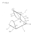
- FIG. 2 is a perspective view showing a state where the first embodiment is assembled.
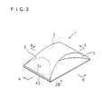
- FIG. 3 is a perspective view showing a sheet assembly of the first embodiment.
- FIG. 4(a) is a plan view of the sheet assembly.
- FIG. 4(b) is a plan view of the sheet assembly.
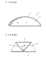
- FIG. 5(a) is a sectional view of the sheet assembly of FIG. 4(a).
- FIG. 5(b) is a sectional view of the sheet assembly of FIG. 4(a).
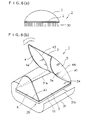
- FIG. 6(a) is a front view showing a state where the present invention is applied to a mop.
- FIG. 6(b) is a perspective view showing a state where the present invention is applied to a mop.
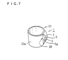
- FIG. 7 is a view showing a state where the present invention is applied to a handle.
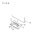
- FIG. 8 is a view showing a state where the present invention is applied to a stand.
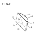
- FIG. 9 is a view showing a state where the present invention is applied to a stand.
- FIG. 10 is a development of a second embodiment of the present invention.
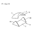
- FIG. 11 is a perspective view showing a state where the second embodiment is assembled.
- FIG. 12(a) is a perspective view of a third embodiment of the present invention.
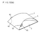
- FIG. 12(b) is a perspective view of a third embodiment of the present invention.
- FIG. 13(a) is a perspective view of a fourth embodiment of the present invention.
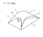
- FIG. 13(b) is a perspective view of a fourth embodiment of the present invention.
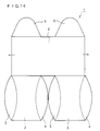
- FIG. 14 is a development of a fifth embodiment of the present invention.
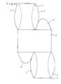
- FIG. 15 is a development of a sixth embodiment of the present invention.
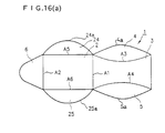
- FIG. 16(a) is a development of a seventh embodiment of the present invention.
- FIG. 16(b) is a perspective view of a seventh embodiment of the present invention.
- FIG. 16(c) is a sectional view of a seventh embodiment of the present invention.
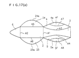
- FIG. 17(a) is a development of an eighth embodiment of the present invention.
- FIG. 17(b) is a perspective view of an eighth embodiment of the present invention.
- FIG. 17(c) is a sectional view of an eighth embodiment of the present invention.
- FIG. 1 is a development showing a sheet assembly of a first embodiment.
- the sheet assembly is formed from one sheet.
- a sheet 1 is made of cardboard, a plastics sheet, or a synthetic paper of polypropylene. Fairly stiff but flexible material should be adopted as the sheet.
- a synthetic paper named "alpha-epo”, a product of Oji Petrochemical & Synthetic Paper Co Ltd with a thickness of 0.95mm is used here.
- the sheet 1 as punched has a predetermined form.
- a centre of the sheet 1 is a parallel-sided, or rectangular first portion 2 having a predetermined width W and a predetermined length L1.
- a second or flexible portion 3 is integrally combined with one edge 2a of the first portion 2.
- the second portion 3 has two opposite curved edges 3c and 3d orienting inwardly thereof.
- Ribs 4 and 5 are integrally combined with the opposite curved edges 3c and 3d of the second portion 3, respectively.
- the ribs 4 and 5 project outwardly from the second portion 3.
- a connecting flap 6 is integrally combined with another edge 2b of the first portion 2.
- the first portion 2 is destined to be a flat component of the article assembled from the sheet 1.
- the second portion 3 and its ribs 4, 5 are destined to be flexed and curved when the article is assembled, and to suit being grasped.
- the first portion 2 is formed to be a rectangle with the predetermined width W and the predetermined length L1. Both edges 2a and 2b on lateral sides of portion 2 are of the same length and function as folding edges A1 and A2. The two remaining edges on top and bottom sides serve as outer peripheral edges 2c and 2d.
- Edges 3a and 3b of the second or flexible portion 3 equals to the width W of the flat portion 3.
- the edge 3a functions as a folding edge A1, and the edge 3b serves as an outer peripheral edge.
- a length L2 of the flexible portion 3 is longer than the length L1 of the flat portion 2.
- combining edges 3c and 3d are provided in a form of predetermined curves.
- the curves of the combining edges 3c and 3d are such as parts of circles, of which distance equals to the width W at the end positions, and which circles approach with each other at the centre position.
- the combining edges serve as folding edges A3 and A4.
- the ribs 4 and 5 are provided on the folding edges A3 and A4. Outer peripheral edges 4a and 5a of the ribs 4 and 5 respectively are formed in a form of a predetermined quadratic curve. Each centre of the outer peripheral edges 4a and 5a is most outwardly projecting.
- Outer peripheral edge 6a of the connecting flap 6 is U-shaped and connects at both its ends with the edge 2b. As illustrated by an alternate long and short dash line in the drawing, side portions 6aa and 6ab of the outer peripheral edge 6a is formed so as to contact parts of the combining edges 3c and 3d.
- the folding edges A1 to A4 are formed to be easily foldable by making notches, recesses or grooves on the sheet 1.
- FIG. 2 is a view showing a state where the sheet 1 thus formed is being folded for assembling.
- Assembling is performed as follows: firstly, fold up the connecting flap 6 and the flexible portion 3 along the folding edges A2 and A1 respectively; next, insert the connecting flap 6 under the edge 3b of the second or flexible portion 3; and then, fold the ribs 4 and 5 inwardly along the folding edges A3 and A4 respectively.
- the flexible portion 3 is so curved that its middle portion bulges outwardly since the length L2 of the flexible portion 3 is longer than the length L1 of the flat portion 2.
- FIG. 3 is a perspective view showing the completed sheet assembly. In this state, the flexible portion 3 curves relative to the flat portion 2, and the ribs 4 and 5 can be held by hands.
- FIGS. 4(a) and 4(b) are plan views of the completed sheet assembly.
- FIGS. 5(a) and 5(b) are sectional views of the same.
- FIG. 5(A) is a sectional view taken along lines A-A of FIG. 3.
- FIG. 5(b) is a sectional view taken along lines B-B of FIG. 3.
- the ribs 4 and 5 contact each other at the centre of the outer peripheral edges 4a and 5a.
- the outer peripheral edges 4a and 5a also contact an upper surface 2A of the flat portion 2.
- the ribs may contact the flat portion along lines shown in FIG. 4(b), depending on distribution of the pressing power applied on the flexible portion.
- forms of the outer peripheral edges 4a and 5a are designed as predetermined lines in such a manner that the edges come into line-contact with the upper surface 2A of the flat portion 2 when being assembled with each other.
- the predetermined line is not limited to a circular arc, and may be a quadratic curve such as a parabolic or hyperbolic curve.
- the outer peripheral edges 4a and 5a are to be modified depending on curving degree of the flexible portion 3.
- the sheet assembly can be erected or assembled when required, and also can be shipped and stored in the flat sheet form, thereby achieving excellent portability. Erection can be performed just by folding the sheet along the folding edges A1 to A4 and then assembling the folded parts.
- the outer peripheral edges 6aa and 6ab of the connecting flap 6 contact the flexible portion 3 and parts of the folding edges A3 and A4 of the ribs 4 and 5, especially the parts near the edge 3b.
- the connecting flap 6 is held inside the flexible portion 3, and the assembled or erected state of the sheet is thereby retained.
- disassembly also can be easily performed by pulling the connecting flap 6 out from the flexible portion 3.
- the sheet assembly which provides a flat surface and a handle, can be put to use in a variety of applications, e.g. as a wiper such as a brush, mop and whiteboard or blackboard wiper, a handle of a cup or a container, and a stand such as a photo-stand, a menu plate and a price board.
- a wiper such as a brush, mop and whiteboard or blackboard wiper
- a handle of a cup or a container e.g. as a wiper such as a brush, mop and whiteboard or blackboard wiper
- a handle of a cup or a container e.g. as a handle of a cup or a container
- a stand such as a photo-stand, a menu plate and a price board.
- a brush 30 is attached to a bottom surface 2B of the flat portion 2.
- the flexible portion 3 is pressed downwardly while being held by hand, the pressure is uniformly exerted on the flat portion 2, so that the brush is brought into close contact with a surface to be cleaned to conduct satisfactory cleaning.
- FIG. 6(b) is a perspective view showing another application of the wiper of this embodiment.
- a mop cloth 31 used here as a wiping cloth has length that is comparable to the length L1 of the flat portion 2 and the width that is beyond the width W of the flat portion 2.
- Both side portions 31a, 31b of the mop cloth 31 are folded up and placed on the upper surface 2A, and then held in place by the outer peripheral edges 4a and 5a.
- elastic material 10 such as sponge may be disposed on the bottom surface 2B and the surface of the material may be covered by the mop cloth 31. Such constitution improves handling thereof in a cleaning operation.
- the bottom surface 2B of the flat portion 2 is attached to a side surface 33a of a cup 33.
- the cup 33 can be supported by holding the curved flexible portion 3.
- the erected sheet assembly is rigid, that the cup 33 can be stably supported by holding the assembly.
- the cup 33 has a flat surface formed on a part of the side surface 33a for contacting the bottom surface 2B of the flat portion 2.
- the sheet assembly is suitable for use as a handle of a paper cup.
- the sheet assembly when used as a stand e.g. for holding a menu card or plate 35, the bottom surface 2B of the flat portion 2 is rested on support surface, e.g. a table. Further, a slit 3G is formed in the centre of the upper surface 3A of the flexible portion 3, along the longitudinal direction of the flexible portion 3 for holding the menu plate 35 therein.
- the menu plate 35 can be held after being inserted into the slit. This menu plate can be held stably since it is held by the pair of the ribs 4,5 inside the flexible portion 3 in the region indicated by an arrow shown in FIG. 4(a).
- the sheet assembly can be used as the stand such as a photo-stand.
- the sheet assembly is laid on a support such as a table in such a manner that the rib 4 or 5 is placed on the table.
- the bottom surface 2B of the flat portion 2 is tilted backward at a predetermined angle from the table. A photograph is attached to the bottom surface 2B.
- the sheet assembly serves as the photo-stand.
- FIG. 10 is a development showing a second embodiment of the present invention.
- a sheet assembly is assembled from two sheets 1A and 1B, and further comprises one more connecting flap.
- the constitution of the present embodiment is similar to that of the first embodiment and explanation thereof will be omitted.
- the sheet 1A provides the flat portion 2 as explained in the first embodiment and two connecting flaps 6A and 6B.
- the connecting flaps 6A and 6B are integrally provided on both the edges 2a and 2b of the flat portion 2 respectively.
- the sheet 1B provides the flexible portion 3 and the pair of the ribs 4 and 5.
- FIG. 11 is a perspective view showing a state where the sheets of the second embodiment are assembled.
- the connecting flaps 6A and 6B of the sheet 1A are folded up along the folding lines A1 and A2.
- the ribs 4 and 5 of the sheet 1B are folded down along the folding lines A3 and A4.
- the sheets are assembled with each other by inserting the connecting flaps 6A and 6B between the folding line A3 of the rib 4 and the folding line A4 of the ribs 5.
- each of the two sheets 1A and 1B is a sheet-form before assembling and the sheet assembly is composed of the sheets by assembling them.
- FIGS. 12(a) and 12(b) are perspective views showing a third embodiment of the present invention.
- This embodiment includes inter-engaging members that retain the article in its assembled state.
- protruding portions 6D, 6D are formed on the outer peripheral edges 6aa and 6ab of the connecting flap 6 respectively.
- Slits 4D,5D are formed adjacent or in the folding lines A3, A4 of the ribs 4, 5 respectively according to the protruding portions 6D, 6D.
- the protruding portions 6D, 6D and the slits 4D, 5D are engaged with each other respectively, thereby retaining the article in its assembled state.
- the combination of the protruding portion(s) and slit(s) can similarly be applied to the second embodiment.
- the protruding portions 6D, 6D are formed on each of the connecting flaps 6A and 6B, and the slits 4D, 5D are formed in or adjacent two portions of each of the fold lines A3, A4 according to the protruding portions 6D, 6D.
- FIGs 13(a) and 13(b) are perspective views showing a fourth embodiment of the present invention.
- the engaging members are modified.
- a hook 21a and an eye 21b as engaging means are attached to the connecting flap 6 and the flexible portion 3 respectively, at positions permitting them to contact each other on erection of the article.
- the hook 21a is fastened to the eye 21b
- the sheet assembly can be held as assembled as shown in FIG. 13(b).
- the connecting flap 6 is superimposed over the flexible portion 3 and attached thereto.
- fastening tapes or adhesive tape usable several times can be adopted.
- FIG. 14 is a developed view showing a fifth embodiment of the present invention.
- a double sheet assembly can be assembled from a sheet cut-out shown in the development.
- the flat portion 2 is expanded in the width direction.
- the flexible portions 3 and the connecting flaps 6 are provided on both ends of the flat portion 2 in the length direction, respectively.
- the flat portion 2 is expanded in the width direction, and the flexible portions 3 and the connecting flaps 6 are symmetrically provided on both ends of the flat portion 2 in the length direction, respectively.
- FIGS. 16(a), 16(b) and 16(c) are views showing a seventh embodiment of the present invention.
- a sheet assembly includes two curved auxiliary ribs 24, 25 integrally combined with two opposite edges in the width direction of the flat portion 2, respectively.
- the opposite edges serve as folding lines A5 and A6, when the auxiliary ribs are folded up in FIG. 16(a).
- Outer peripheral edges 24a and 25a of the auxiliary ribs 24 and 25 are predetermined curves.
- the ribs 4 and 5 are bent, the connecting flap 6 is engaged with the curved flexible portion 3, and finally the auxiliary ribs 24 and 25 are bent inwardly.
- the auxiliary ribs 24 and 25 are bent inwardly over the ribs 4 and 5.
- 16(c) is a sectional view taken along lines C-C of FIG. 16(b).
- the ribs 4 and 5 are supported by the auxiliary ribs 24 and 25. In this way, since the ribs 4 and 5 are fixedly supported, pressing force downwardly applied on to the curved flexible portion 3 can be transmitted uniformly to the flat portion 2. Further, rigidity of the entire of the sheet assembly is improved.
- FIGS. 17(a), 17(b) and 17(c) are views showing an eighth embodiment of the present invention.
- a sheet assembly includes modified ribs 4 and 5 in addition to the auxiliary ribs 24 and 25 explained in the seventh embodiment.
- the ribs 4 and 5 include folding edges A7 and A8 formed in the middle of the ribs and extending along the length direction thereof, according to the folding edges A3 and A4, respectively.
- support ribs 4F and 5F are integrally formed on the folding edges A7 and A8 at the outer portions of the ribs 4 and 5, respectively.
- the ribs 4 and 5 are downwardly bent from the flexible portion 3 along the folding edges A3 and A4, the support ribs 4F and 5F are upwardly bent from the ribs 4 and 5 along the folding edges A7 and A8.
- FIG. 17(b) and a sectional view of FIG. 17(c) taken along lines D-D of FIG. 17(b) the support ribs 4F and 5F as parts of the ribs 4 and 5 spread downwardly outwardly and contact the flat portion 2 at the outer peripheral edges 4a and 5a, respectively.
- the ribs 4 and 5 are supported by the auxiliary ribs 24 and 25.
- a sheet of a predetermined form is folded and assembled in such a manner that the ribs are provided between the upper curved flexible portion and the lower flat portion.
- the ensuing constitution is stiff or rigid after assembly. The assembling operation is easy to perform.
- Pressing force applied onto the curved or flexed portion can be uniformly transmitted to the flat portion. Further, the sheet assembly can be easily disassembled back to a flat sheet form. Accordingly, the sheet assembly is compact and portable in an emergency.
- a sheet assembly having good stiffness and strength after assembling and advantageous portability thanks to lightness and thinness can be obtained at a low cost.
Landscapes
- Engineering & Computer Science (AREA)
- Mechanical Engineering (AREA)
- Purses, Travelling Bags, Baskets, Or Suitcases (AREA)
- Cleaning Implements For Floors, Carpets, Furniture, Walls, And The Like (AREA)
- Mirrors, Picture Frames, Photograph Stands, And Related Fastening Devices (AREA)
- Paper (AREA)
Applications Claiming Priority (2)
| Application Number | Priority Date | Filing Date | Title |
|---|---|---|---|
| JP10215872A JP2000043841A (ja) | 1998-07-30 | 1998-07-30 | シート構造体 |
| JP21587298 | 1998-07-30 |
Publications (1)
| Publication Number | Publication Date |
|---|---|
| EP0985604A1 true EP0985604A1 (fr) | 2000-03-15 |
Family
ID=16679668
Family Applications (1)
| Application Number | Title | Priority Date | Filing Date |
|---|---|---|---|
| EP99306054A Withdrawn EP0985604A1 (fr) | 1998-07-30 | 1999-07-29 | Structure formée à partir d'une feuille |
Country Status (2)
| Country | Link |
|---|---|
| EP (1) | EP0985604A1 (fr) |
| JP (1) | JP2000043841A (fr) |
Families Citing this family (2)
| Publication number | Priority date | Publication date | Assignee | Title |
|---|---|---|---|---|
| DE102011011673B4 (de) * | 2011-02-15 | 2016-07-07 | Vesta Heyn | Zuschnitt aus einem biegsamen, flächigen Material zur Herstellung eines Bilderrahmens sowie ein Bilderrahmen gefertigt aus dem Zuschnitt |
| RU189160U1 (ru) * | 2019-02-12 | 2019-05-15 | Тимур Раисович Нугаев | Декоративное изделие в виде домика |
Citations (7)
| Publication number | Priority date | Publication date | Assignee | Title |
|---|---|---|---|---|
| GB796271A (en) * | 1956-11-09 | 1958-06-11 | Hugh Stevenson & Sons Ltd | Improvements in or relating to boxes or cartons formed of cardboard or like sheet material |
| FR1249386A (fr) * | 1959-11-13 | 1960-12-30 | Panneau publicitaire en forme de chevalet, pour étalage | |
| GB884121A (en) * | 1957-05-23 | 1961-12-06 | Robinson E S & A Ltd | Improvements in carriers |
| FR2277003A1 (fr) * | 1974-07-02 | 1976-01-30 | Flax V | Ecrin |
| DE2802385A1 (de) * | 1978-01-20 | 1979-07-26 | Leunisman Grossdruckerei Fuer | Behaelter fuer lebensmittel |
| WO1995010454A1 (fr) * | 1993-10-08 | 1995-04-20 | M-Pak Limited | Ebauches de carton en forme de coussin |
| US5592768A (en) * | 1994-12-06 | 1997-01-14 | Testa; Richard J. | Photograph display device |
-
1998
- 1998-07-30 JP JP10215872A patent/JP2000043841A/ja active Pending
-
1999
- 1999-07-29 EP EP99306054A patent/EP0985604A1/fr not_active Withdrawn
Patent Citations (7)
| Publication number | Priority date | Publication date | Assignee | Title |
|---|---|---|---|---|
| GB796271A (en) * | 1956-11-09 | 1958-06-11 | Hugh Stevenson & Sons Ltd | Improvements in or relating to boxes or cartons formed of cardboard or like sheet material |
| GB884121A (en) * | 1957-05-23 | 1961-12-06 | Robinson E S & A Ltd | Improvements in carriers |
| FR1249386A (fr) * | 1959-11-13 | 1960-12-30 | Panneau publicitaire en forme de chevalet, pour étalage | |
| FR2277003A1 (fr) * | 1974-07-02 | 1976-01-30 | Flax V | Ecrin |
| DE2802385A1 (de) * | 1978-01-20 | 1979-07-26 | Leunisman Grossdruckerei Fuer | Behaelter fuer lebensmittel |
| WO1995010454A1 (fr) * | 1993-10-08 | 1995-04-20 | M-Pak Limited | Ebauches de carton en forme de coussin |
| US5592768A (en) * | 1994-12-06 | 1997-01-14 | Testa; Richard J. | Photograph display device |
Also Published As
| Publication number | Publication date |
|---|---|
| JP2000043841A (ja) | 2000-02-15 |
Similar Documents
| Publication | Publication Date | Title |
|---|---|---|
| EP1048576A1 (fr) | Ensemble de conditionnement polyvalent | |
| JPH11130049A (ja) | 包装補助具 | |
| CN1639013A (zh) | 可折叠杯 | |
| US6502744B1 (en) | Folding laminated containers | |
| CN218142762U (zh) | 一种搬家用纸箱 | |
| JP2000043841A (ja) | シート構造体 | |
| JPH0714181Y2 (ja) | 把手付き紙箱 | |
| JPH0546723U (ja) | カートンケースの緩衝材 | |
| JP2004050613A (ja) | カード及び筒状体形成シート部材 | |
| JPH0110370Y2 (fr) | ||
| JP3240713U (ja) | 包装容器及び展開体 | |
| JP4147364B2 (ja) | 桟付収納箱 | |
| JP3757257B2 (ja) | バイアル起立台とアンプル収納部を具備した容器 | |
| JP3063919U (ja) | 容 器 | |
| JPS6134257Y2 (fr) | ||
| JPS5826918Y2 (ja) | 紙製折畳み箱 | |
| WO2011079427A1 (fr) | Structure de cadre servant à maintenir des gobelets | |
| GB2369769A (en) | Fold-flat tray | |
| JP2002154575A (ja) | シートとシートの結合構造 | |
| JP3659808B2 (ja) | 押圧印刷器 | |
| EP0406495A1 (fr) | Poignée extensible | |
| JP2591506Y2 (ja) | 清掃用具 | |
| JP3834941B2 (ja) | 梱包装置 | |
| JP3003474U (ja) | 厚地織物の見本帳等の台枠 | |
| JP3954292B2 (ja) | 包装容器 |
Legal Events
| Date | Code | Title | Description |
|---|---|---|---|
| PUAI | Public reference made under article 153(3) epc to a published international application that has entered the european phase |
Free format text: ORIGINAL CODE: 0009012 |
|
| 17P | Request for examination filed |
Effective date: 19990814 |
|
| AK | Designated contracting states |
Kind code of ref document: A1 Designated state(s): DE FR GB |
|
| AX | Request for extension of the european patent |
Free format text: AL;LT;LV;MK;RO;SI |
|
| AKX | Designation fees paid |
Free format text: DE FR GB |
|
| 17Q | First examination report despatched |
Effective date: 20010910 |
|
| GRAH | Despatch of communication of intention to grant a patent |
Free format text: ORIGINAL CODE: EPIDOS IGRA |
|
| STAA | Information on the status of an ep patent application or granted ep patent |
Free format text: STATUS: THE APPLICATION IS DEEMED TO BE WITHDRAWN |
|
| 18D | Application deemed to be withdrawn |
Effective date: 20030819 |