EP0985615A2 - Gerät und Verfahren zum Messen einer Dimension eines Gegendstandes - Google Patents
Gerät und Verfahren zum Messen einer Dimension eines Gegendstandes Download PDFInfo
- Publication number
- EP0985615A2 EP0985615A2 EP99306357A EP99306357A EP0985615A2 EP 0985615 A2 EP0985615 A2 EP 0985615A2 EP 99306357 A EP99306357 A EP 99306357A EP 99306357 A EP99306357 A EP 99306357A EP 0985615 A2 EP0985615 A2 EP 0985615A2
- Authority
- EP
- European Patent Office
- Prior art keywords
- sheet
- reflective surface
- electro
- reflective
- arm
- Prior art date
- Legal status (The legal status is an assumption and is not a legal conclusion. Google has not performed a legal analysis and makes no representation as to the accuracy of the status listed.)
- Granted
Links
- 238000000034 method Methods 0.000 title claims abstract description 6
- 230000003287 optical effect Effects 0.000 claims description 23
- 238000012986 modification Methods 0.000 description 3
- 230000004048 modification Effects 0.000 description 3
- 238000002310 reflectometry Methods 0.000 description 3
- 238000007792 addition Methods 0.000 description 2
- 239000000463 material Substances 0.000 description 2
- 241000669003 Aspidiotus destructor Species 0.000 description 1
- 230000006978 adaptation Effects 0.000 description 1
- 230000015572 biosynthetic process Effects 0.000 description 1
- 230000015556 catabolic process Effects 0.000 description 1
- 238000011109 contamination Methods 0.000 description 1
- 230000001276 controlling effect Effects 0.000 description 1
- 230000002596 correlated effect Effects 0.000 description 1
- 230000000875 corresponding effect Effects 0.000 description 1
- 238000006731 degradation reaction Methods 0.000 description 1
- 239000000428 dust Substances 0.000 description 1
- 238000004519 manufacturing process Methods 0.000 description 1
- 238000005259 measurement Methods 0.000 description 1
- 229920003023 plastic Polymers 0.000 description 1
- 239000004033 plastic Substances 0.000 description 1
- 238000011282 treatment Methods 0.000 description 1
Images


Classifications
-
- G—PHYSICS
- G03—PHOTOGRAPHY; CINEMATOGRAPHY; ANALOGOUS TECHNIQUES USING WAVES OTHER THAN OPTICAL WAVES; ELECTROGRAPHY; HOLOGRAPHY
- G03G—ELECTROGRAPHY; ELECTROPHOTOGRAPHY; MAGNETOGRAPHY
- G03G15/00—Apparatus for electrographic processes using a charge pattern
- G03G15/65—Apparatus which relate to the handling of copy material
-
- B—PERFORMING OPERATIONS; TRANSPORTING
- B65—CONVEYING; PACKING; STORING; HANDLING THIN OR FILAMENTARY MATERIAL
- B65H—HANDLING THIN OR FILAMENTARY MATERIAL, e.g. SHEETS, WEBS, CABLES
- B65H1/00—Supports or magazines for piles from which articles are to be separated
-
- B—PERFORMING OPERATIONS; TRANSPORTING
- B65—CONVEYING; PACKING; STORING; HANDLING THIN OR FILAMENTARY MATERIAL
- B65H—HANDLING THIN OR FILAMENTARY MATERIAL, e.g. SHEETS, WEBS, CABLES
- B65H7/00—Controlling article feeding, separating, pile-advancing, or associated apparatus, to take account of incorrect feeding, absence of articles, or presence of faulty articles
- B65H7/02—Controlling article feeding, separating, pile-advancing, or associated apparatus, to take account of incorrect feeding, absence of articles, or presence of faulty articles by feelers or detectors
- B65H7/14—Controlling article feeding, separating, pile-advancing, or associated apparatus, to take account of incorrect feeding, absence of articles, or presence of faulty articles by feelers or detectors by photoelectric feelers or detectors
-
- B—PERFORMING OPERATIONS; TRANSPORTING
- B65—CONVEYING; PACKING; STORING; HANDLING THIN OR FILAMENTARY MATERIAL
- B65H—HANDLING THIN OR FILAMENTARY MATERIAL, e.g. SHEETS, WEBS, CABLES
- B65H9/00—Registering, e.g. orientating, articles; Devices therefor
- B65H9/04—Fixed or adjustable stops or gauges
-
- B—PERFORMING OPERATIONS; TRANSPORTING
- B65—CONVEYING; PACKING; STORING; HANDLING THIN OR FILAMENTARY MATERIAL
- B65H—HANDLING THIN OR FILAMENTARY MATERIAL, e.g. SHEETS, WEBS, CABLES
- B65H2511/00—Dimensions; Position; Numbers; Identification; Occurrences
- B65H2511/10—Size; Dimensions
-
- B—PERFORMING OPERATIONS; TRANSPORTING
- B65—CONVEYING; PACKING; STORING; HANDLING THIN OR FILAMENTARY MATERIAL
- B65H—HANDLING THIN OR FILAMENTARY MATERIAL, e.g. SHEETS, WEBS, CABLES
- B65H2511/00—Dimensions; Position; Numbers; Identification; Occurrences
- B65H2511/10—Size; Dimensions
- B65H2511/12—Width
-
- B—PERFORMING OPERATIONS; TRANSPORTING
- B65—CONVEYING; PACKING; STORING; HANDLING THIN OR FILAMENTARY MATERIAL
- B65H—HANDLING THIN OR FILAMENTARY MATERIAL, e.g. SHEETS, WEBS, CABLES
- B65H2511/00—Dimensions; Position; Numbers; Identification; Occurrences
- B65H2511/20—Location in space
- B65H2511/22—Distance
-
- B—PERFORMING OPERATIONS; TRANSPORTING
- B65—CONVEYING; PACKING; STORING; HANDLING THIN OR FILAMENTARY MATERIAL
- B65H—HANDLING THIN OR FILAMENTARY MATERIAL, e.g. SHEETS, WEBS, CABLES
- B65H2515/00—Physical entities not provided for in groups B65H2511/00 or B65H2513/00
- B65H2515/60—Optical characteristics, e.g. colour, light
-
- B—PERFORMING OPERATIONS; TRANSPORTING
- B65—CONVEYING; PACKING; STORING; HANDLING THIN OR FILAMENTARY MATERIAL
- B65H—HANDLING THIN OR FILAMENTARY MATERIAL, e.g. SHEETS, WEBS, CABLES
- B65H2553/00—Sensing or detecting means
- B65H2553/40—Sensing or detecting means using optical, e.g. photographic, elements
- B65H2553/41—Photoelectric detectors
- B65H2553/414—Photoelectric detectors involving receptor receiving light reflected by a reflecting surface and emitted by a separate emitter
-
- G—PHYSICS
- G03—PHOTOGRAPHY; CINEMATOGRAPHY; ANALOGOUS TECHNIQUES USING WAVES OTHER THAN OPTICAL WAVES; ELECTROGRAPHY; HOLOGRAPHY
- G03G—ELECTROGRAPHY; ELECTROPHOTOGRAPHY; MAGNETOGRAPHY
- G03G2215/00—Apparatus for electrophotographic processes
- G03G2215/00362—Apparatus for electrophotographic processes relating to the copy medium handling
- G03G2215/00535—Stable handling of copy medium
- G03G2215/00611—Detector details, e.g. optical detector
- G03G2215/00616—Optical detector
-
- G—PHYSICS
- G03—PHOTOGRAPHY; CINEMATOGRAPHY; ANALOGOUS TECHNIQUES USING WAVES OTHER THAN OPTICAL WAVES; ELECTROGRAPHY; HOLOGRAPHY
- G03G—ELECTROGRAPHY; ELECTROPHOTOGRAPHY; MAGNETOGRAPHY
- G03G2215/00—Apparatus for electrophotographic processes
- G03G2215/00362—Apparatus for electrophotographic processes relating to the copy medium handling
- G03G2215/00535—Stable handling of copy medium
- G03G2215/00717—Detection of physical properties
- G03G2215/00734—Detection of physical properties of sheet size
Definitions
- This invention relates to apparatus and a method for measuring a dimension of an object and has particular application to measuring a dimension, such as the width or length, of a sheet.
- the invention will be particularly described hereunder in relation to its use in a sheet feeder, that is, a unit for supporting sheets for feeding to a printer.
- a sheet feeder that is, a unit for supporting sheets for feeding to a printer.
- the sheets will be paper, but the invention is useable for other types of sheets, for example transparencies.
- the invention is to be described in relation to this particular application, it is to be understood that it can be otherwise applied for measuring a dimension of other suitable objects.
- Printers with which the invention, as applied to a sheet feeder, is useable which may be for example of the electrophotographic, ink jet or laser jet type, are generally designed to print on a number of different sheet sizes. These sizes are standardized and include legal, letter, A3, A4, B5 and others.
- Known sheet feeders such as trays, containers or cassettes for printers are able to accommodate different sizes of sheets by including sheet size guides which are manually adjustable to fit a desired sheet size.
- sheet size guides which are manually adjustable to fit a desired sheet size.
- an operator knows the size of the sheets stored in a sheet feeder and appropriately formats the printer driver or copying machine for that size.
- a more desirable arrangement would be to sense automatically the sheet size and generate an electrical signal which can be used to control a printing function related to the sheet size.
- a signal which is representative of the size of sheets in a sheet feeder could be forwarded to a printer driver for the driver to determine whether the sheet size is appropriate for the image to be printed. Should the image not be compatible with the sensed sheet size, the printing can be altered and/or a signal sent to the operator to correct the matter.
- Another more intelligent option is for the signal to initiate an automatic scaling of an image to fit onto the sheet size which is in the sheet feeder.
- United States Patent No. 5573236 discloses a sheet storage tray which is adapted to detect the size of sheets in the tray.
- This adaptation comprises the provision of an optical reflective sensor and a continuously variably graduated scale associated with a sheet guide. Movement of the sheet guide in the tray causes the scale to be moved past the sensor.
- the sensor When the guide is located against a stack of sheets, the sensor generates a signal having a strength which is determined by the relative position of the scale. Thus the strength of the signal is representative of the position of the guide and thus the size of the sheets.
- Example scales which are disclosed are a grey scale which varies from black to white with levels of grey therebetween, a continuous colour pattern that varies in colour from end to end, a variably transparent scale and binary scales to give digital signal outputs.
- the present invention provides apparatus and a method for measuring a dimension of an object which involves the provision of two elements, one of which includes an electro-optical sensor for transmitting and receiving an optical signal and the other of which includes a reflective surface.
- the elements are arranged such that the reflective surface faces and is variably spaced from the electro-optical sensor according to different adjustment positions for one of the elements whilst the other is stationary.
- the adjustable element is positionable against a portion of the object and this position represents the dimension of the object which is to be measured.
- the spacing between the sensor and the reflective surface at this position which can be correlated to the dimension being measured, is then determinable from the strength of the reflected optical signal and thus the magnitude of an electrical output signal from the sensor.
- the output of the sensor provides a measure of the dimension of the object, that is, the invention relies on a variation in the distance between an electro-optical sensor and a reflective surface associated with an element as the element moves relative to the sensor to produce a variation in an electrical output signal of the sensor.
- a particular distance as determined by a particular size of the object being measured will generate a particular magnitude for the signal which is related to the object size.
- the object is a sheet for passage through a printer and the adjustable element is a guide for an edge of the sheet.
- the portion of the object against which the adjustable element is positionable is an edge of the sheet.
- the direction of adjustment of the adjustable element and the dimension being measured are parallel and extend substantially orthogonally to a path of the optical signal between the electro-optical sensor and the reflective surface. This arrangement allows for a much reduced optical path length compared to the dimension being measured.
- any additional treatments to enhance the reflectivity of the reflective surface of the element concerned will be required other than the normal formation operations for that element. That is, the reflectivity can be ensured merely by the provision of a normally smooth surface provided the material of the element is appropriate. This material can be a plastics having a light colour. Effectively the surface provides a substantially constant reflectivity throughout its length.
- the first element comprises a sheet guide which carries an arm.
- This sheet guide may be slidably mounted relative to a base of a sheet feeder such that the arm moves lengthwise past the sensor.
- the arm may be tapered along its length such that the reflective surface is provided by a surface of the arm which slopes relative to the sensor.
- the arm may be stepped along its length to define reflective surface sections wherein each section is differently spaced from the sensor.
- the first element may comprise a sheet guide which carries the electro-optical sensor and the second element is an arm which is stationary relative to the base.
- the arm may be tapered or stepped relative to the sensor as described above.
- the sensor is mounted with the sheet guide such that it is moved by the guide lengthwise of the arm.
- the above described arrangements are appropriate for detecting a single dimension, that is, the length or width of a sheet on a sheet feeder. Two such arrangements can be used to detect both dimensions, that is, length and width of a sheet.
- a method for measuring a dimension of an object comprising providing an adjustable first element and a stationary second element, wherein one of the first and second elements includes an electro-optical sensor for transmitting and receiving an optical signal and the other of the first and second elements includes a reflective surface which faces and is spaced from said electro-optical sensor, adjusting the first element to a position wherein it contacts a portion of the object, operating the electro-optical sensor such that it transmits an optical signal and receives a portion of that signal which is reflected from the reflective surface to provide an electrical output signal having a magnitude, wherein the strength of the reflected signal and thus the magnitude of the electrical output signal is determined by the spacing between the electro-optical sensor and the reflective surface according to the adjusted position of the first element, whereby the magnitude of the electrical output signal is a measure of the dimension of the object as determined by the adjusted position of the first element.
- the dimension being measured preferably extends substantially orthogonally to a path of the optical signal between the electro-optical sensor and the reflective surface, and the adjustment of the first element is preferably in a direction parallel to the dimension being measured.
- the object to be measured is a sheet and the first and second elements are operatively associated with a sheet feeder for a printer which contains the sheet, wherein the first element is a sheet guide and said portion of the object is an edge of the sheet.
- Fig. 1 illustrates a top plan view of a printer having a sheet feeder which utilizes one embodiment of the invention.
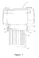
- Fig. 2 is an underneath perspective view of a portion of a sheet feeder of the Fig. 1 printer.
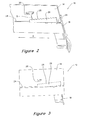
- Fig. 3 is a plan view from underneath of the sheet feeder portion shown in Fig. 2.
- Fig. 4 is a view similar to Fig. 2 of portion of another sheet feeder embodiment.
- Fig. 5 is a view from underneath of the sheet feeder portion of Fig. 4.
- Fig. 6 is a view similar to Fig. 2 of portion of yet another sheet feeder embodiment.
- a sheet feeder 10 is for holding a stack of sheets (not shown) from which individual sheets can be fed for passage through a printer indicated generally by reference 12.
- the function of the sheet feeder 10 is to locate the sheets, for example of paper, accurately for presentation to the printer's pick-up mechanism (not shown).
- the sheet feeder 10 comprises a base 14 to which a plate 16 having a paper stopper is attachable in a known manner.
- a stack of sheets rests on the upper surfaces of the base 14 and plate 16.
- a paper guide 18 is adjustable widthwise of base 14 until it comes into contact with the edge of the stack of paper.
- the base 14 includes a fixed paper guide 20 such that the adjustment of movable guide 18 against the paper edge locates the paper between guides 18 and 20.
- the plate 16 is then movable lengthwise until its paper stopper 22 comes into contact with the "rear" edge of the stack of papers. This locates the paper lengthwise relative to the printer 12.
- FIG. 2 shows a portion of base 14 and the movable guide 18.
- the guide 18 is mounted for movement along a slot 24 in base 14 and includes an arm 26 attached thereto.
- Arm 26 extends widthwise of base 14 in close proximity to its undersurface and includes a tapered surface 28.
- Surface 28 is reflective and faces a reflective photosensor 30 which is fixedly mounted to the undersurface of the base 14.
- the guide 18 and tapered arm 26 assembly comprise a first element of the invention that is associated with the base 14 and the reflective photosensor 20 is a second stationary element associated with the base 14.
- Reflective photosensor 30 transmits an optical signal towards surface 28 and receives the reflected optical signal therefrom as represented by arrow B which illustrates the path distance of the optical signal. Movement of guide 18 widthwise of the base 14 correspondingly moves tapered arm 26 past optical sensor 30 such that the path length B is varied. This causes the strength of the reflected optical signal and thus the electrical signal output of the sensor 30 to vary. This variation can be related to the position of the paper guide 18 and thus the width of the sheets on the base when the guide 18 is in contact with their edge. Thus the sensor 30 provides an electrical output signal which represents a dimension of a sheet supported on the base 14 when the guide arm 18 is adjusted to a position in contact with an edge of the sheet.
- An example reflective photosensor 30 which can be used is manufactured by Rohm under the designation RPR-359F.
- Fig. 6 illustrates a modification similar to that of the Figs. 4 and 5 embodiment but wherein the arm 26 is stepped along its length instead of being tapered, to provide a number of reflective surface sections 28', 28", 28"' etc. Each reflective surface section 28', 28", etc. is spaced a fixed distance from the sensor 30 and location of the sensor opposite a particular section 28', 28", etc. will give an electrical output signal which represents sheets of a particular size. It is also within the scope of the invention that the stepped arm 26 can be movable and the sensor 30 stationary (similar to the Figs. 2 and 3 embodiment).
- the above described embodiments are for measuring a "width" dimension of the sheets.
- a similar arrangement can be associated with the movable plate 16 for measuring a "length" dimension of the sheets such that signals representing the width and length of sheets on the sheet feeder can be generated for forwarding to a printer driver or other print controlling portion of a printing machine.
Landscapes
- Engineering & Computer Science (AREA)
- Mechanical Engineering (AREA)
- Physics & Mathematics (AREA)
- General Physics & Mathematics (AREA)
- Controlling Sheets Or Webs (AREA)
- Length Measuring Devices By Optical Means (AREA)
- Manual Feeding Of Sheets (AREA)
Applications Claiming Priority (2)
| Application Number | Priority Date | Filing Date | Title |
|---|---|---|---|
| SG9803607 | 1998-09-11 | ||
| SG9803607 | 1998-09-11 |
Publications (3)
| Publication Number | Publication Date |
|---|---|
| EP0985615A2 true EP0985615A2 (de) | 2000-03-15 |
| EP0985615A3 EP0985615A3 (de) | 2000-12-27 |
| EP0985615B1 EP0985615B1 (de) | 2003-04-23 |
Family
ID=20430092
Family Applications (1)
| Application Number | Title | Priority Date | Filing Date |
|---|---|---|---|
| EP99306357A Expired - Lifetime EP0985615B1 (de) | 1998-09-11 | 1999-08-11 | Gerät und Verfahren zum Messen einer Dimension eines Gegendstandes |
Country Status (4)
| Country | Link |
|---|---|
| US (1) | US6164639A (de) |
| EP (1) | EP0985615B1 (de) |
| JP (1) | JP2000088530A (de) |
| DE (1) | DE69907100T2 (de) |
Cited By (1)
| Publication number | Priority date | Publication date | Assignee | Title |
|---|---|---|---|---|
| NL1023745C2 (nl) * | 2003-06-25 | 2004-12-28 | Buhrs Zaandam Bv | Feeder voorzien van automatische formaatherkenning. |
Families Citing this family (7)
| Publication number | Priority date | Publication date | Assignee | Title |
|---|---|---|---|---|
| TW509219U (en) * | 2001-12-31 | 2002-11-01 | Avision Inc | Detecting device for positions of document placement |
| JP4072495B2 (ja) * | 2003-12-15 | 2008-04-09 | キヤノン株式会社 | シート検出装置 |
| JP4709044B2 (ja) * | 2006-03-27 | 2011-06-22 | キヤノン株式会社 | シート給送装置及び画像形成装置 |
| TWM330197U (en) * | 2007-05-08 | 2008-04-11 | Tsc Auto Id Technology Co Ltd | Sheet sensor for tab printer |
| KR20110081703A (ko) * | 2010-01-08 | 2011-07-14 | 삼성전자주식회사 | 용지적재대, 용지급지장치와 이를 가지는 화상형성장치 및 그 제어방법 |
| JP6839949B2 (ja) * | 2016-09-30 | 2021-03-10 | 京セラドキュメントソリューションズ株式会社 | シート積載ユニットおよびそれを備えたシート搬送装置並びに画像形成装置 |
| US20190021178A1 (en) | 2017-07-14 | 2019-01-17 | Panduit Corp. | Faux Column Intermediate Distribution Frame Enclosure |
Citations (1)
| Publication number | Priority date | Publication date | Assignee | Title |
|---|---|---|---|---|
| US5573236A (en) | 1994-08-05 | 1996-11-12 | Xerox Corporation | Variable sheet guide position sensor |
Family Cites Families (2)
| Publication number | Priority date | Publication date | Assignee | Title |
|---|---|---|---|---|
| US3813166A (en) * | 1973-03-07 | 1974-05-28 | Us Army | Optical displacement indicator |
| EP0650100B1 (de) * | 1993-10-22 | 1999-04-28 | Canon Kabushiki Kaisha | Blattdickenmesseinrichtung in einem Abbildungsapparat |
-
1999
- 1999-01-08 US US09/227,233 patent/US6164639A/en not_active Expired - Fee Related
- 1999-08-11 EP EP99306357A patent/EP0985615B1/de not_active Expired - Lifetime
- 1999-08-11 DE DE69907100T patent/DE69907100T2/de not_active Expired - Fee Related
- 1999-09-03 JP JP11249578A patent/JP2000088530A/ja active Pending
Patent Citations (1)
| Publication number | Priority date | Publication date | Assignee | Title |
|---|---|---|---|---|
| US5573236A (en) | 1994-08-05 | 1996-11-12 | Xerox Corporation | Variable sheet guide position sensor |
Cited By (3)
| Publication number | Priority date | Publication date | Assignee | Title |
|---|---|---|---|---|
| NL1023745C2 (nl) * | 2003-06-25 | 2004-12-28 | Buhrs Zaandam Bv | Feeder voorzien van automatische formaatherkenning. |
| EP1491448A1 (de) * | 2003-06-25 | 2004-12-29 | Buhrs-Zaandam B.V. | Zuführeinrichtung mit einem System zur automatischen Grössenerkennung. |
| US7089711B2 (en) | 2003-06-25 | 2006-08-15 | Buhrs-Zaandam B.V. | Feeder provided with automatic size recognition for a packaging line |
Also Published As
| Publication number | Publication date |
|---|---|
| EP0985615A3 (de) | 2000-12-27 |
| DE69907100D1 (de) | 2003-05-28 |
| DE69907100T2 (de) | 2003-12-11 |
| EP0985615B1 (de) | 2003-04-23 |
| JP2000088530A (ja) | 2000-03-31 |
| US6164639A (en) | 2000-12-26 |
Similar Documents
| Publication | Publication Date | Title |
|---|---|---|
| EP0695706B1 (de) | Bogenstützwand-Positionssensor | |
| EP0684140B1 (de) | Druckmedienzuführgerät mit Medienparameterdektionsfähigkeit | |
| US5252991A (en) | Media edge sensor utilizing a laser beam scanner | |
| US8520266B2 (en) | Method and apparatus for measuring image on paper registration | |
| US5127752A (en) | Device and method of registering image relative to border of printed media | |
| US5810494A (en) | Apparatus for working on sheets of sheet material and sheet material for use therewith | |
| JP2000131243A (ja) | 反射型光センサ | |
| EP0985615B1 (de) | Gerät und Verfahren zum Messen einer Dimension eines Gegendstandes | |
| US5971392A (en) | Device for calculating sheet number in a sheet feeder and method for calculating the same | |
| JP4294126B2 (ja) | コピー基体のエッジの決定方法 | |
| EP0985541B1 (de) | Vorrichtung zur Erfassung einer Bogenstapelhöhe | |
| US8517376B2 (en) | Print system with linear encoder for tray print media sizing | |
| JP2009126610A (ja) | 画像形成装置 | |
| US20090142082A1 (en) | Method of estimating a distance | |
| US6586759B1 (en) | Method and apparatus for aligning an optical detecting device | |
| US20080107466A1 (en) | Printing Apparatus | |
| US20080205918A1 (en) | Image forming apparatus | |
| JP2007076797A (ja) | 画像形成装置 | |
| JP3948311B2 (ja) | 印刷シートの判別装置、印刷装置、コンピュータプログラム、コンピュータシステム、及び、印刷シートの判別方法 | |
| TWI574906B (zh) | 紙張尺寸偵測裝置及其偵測方法 | |
| EP0864931A1 (de) | Reflektometer und Verfahren zur Überwachung der Dichte von bedrucktem Material | |
| JP2001255135A (ja) | 可動部材の変位測定装置及び印刷媒体のサイズ測定装置 | |
| JP7552403B2 (ja) | 画像形成装置及びプログラム | |
| JPH04215001A (ja) | シート厚検出機構 | |
| JPS6179686A (ja) | 印字装置 |
Legal Events
| Date | Code | Title | Description |
|---|---|---|---|
| PUAI | Public reference made under article 153(3) epc to a published international application that has entered the european phase |
Free format text: ORIGINAL CODE: 0009012 |
|
| AK | Designated contracting states |
Kind code of ref document: A2 Designated state(s): DE FR GB |
|
| AX | Request for extension of the european patent |
Free format text: AL;LT;LV;MK;RO;SI |
|
| PUAL | Search report despatched |
Free format text: ORIGINAL CODE: 0009013 |
|
| AK | Designated contracting states |
Kind code of ref document: A3 Designated state(s): AT BE CH CY DE DK ES FI FR GB GR IE IT LI LU MC NL PT SE |
|
| AX | Request for extension of the european patent |
Free format text: AL;LT;LV;MK;RO;SI |
|
| RIC1 | Information provided on ipc code assigned before grant |
Free format text: 7B 65H 7/14 A |
|
| RAP1 | Party data changed (applicant data changed or rights of an application transferred) |
Owner name: HEWLETT-PACKARD COMPANY, A DELAWARE CORPORATION |
|
| 17P | Request for examination filed |
Effective date: 20010409 |
|
| AKX | Designation fees paid |
Free format text: DE FR GB |
|
| 17Q | First examination report despatched |
Effective date: 20020117 |
|
| GRAH | Despatch of communication of intention to grant a patent |
Free format text: ORIGINAL CODE: EPIDOS IGRA |
|
| GRAH | Despatch of communication of intention to grant a patent |
Free format text: ORIGINAL CODE: EPIDOS IGRA |
|
| GRAA | (expected) grant |
Free format text: ORIGINAL CODE: 0009210 |
|
| RIN1 | Information on inventor provided before grant (corrected) |
Inventor name: YEO, ENG GUAN Inventor name: GOH KING LING, JULIUS Inventor name: TOH, CHIEW TENG |
|
| AK | Designated contracting states |
Designated state(s): DE FR GB |
|
| REG | Reference to a national code |
Ref country code: GB Ref legal event code: FG4D |
|
| REF | Corresponds to: |
Ref document number: 69907100 Country of ref document: DE Date of ref document: 20030528 Kind code of ref document: P |
|
| ET | Fr: translation filed | ||
| PLBE | No opposition filed within time limit |
Free format text: ORIGINAL CODE: 0009261 |
|
| STAA | Information on the status of an ep patent application or granted ep patent |
Free format text: STATUS: NO OPPOSITION FILED WITHIN TIME LIMIT |
|
| 26N | No opposition filed |
Effective date: 20040126 |
|
| PGFP | Annual fee paid to national office [announced via postgrant information from national office to epo] |
Ref country code: GB Payment date: 20070830 Year of fee payment: 9 |
|
| PGFP | Annual fee paid to national office [announced via postgrant information from national office to epo] |
Ref country code: DE Payment date: 20071001 Year of fee payment: 9 |
|
| PGFP | Annual fee paid to national office [announced via postgrant information from national office to epo] |
Ref country code: FR Payment date: 20070817 Year of fee payment: 9 |
|
| GBPC | Gb: european patent ceased through non-payment of renewal fee |
Effective date: 20080811 |
|
| REG | Reference to a national code |
Ref country code: FR Ref legal event code: ST Effective date: 20090430 |
|
| PG25 | Lapsed in a contracting state [announced via postgrant information from national office to epo] |
Ref country code: FR Free format text: LAPSE BECAUSE OF NON-PAYMENT OF DUE FEES Effective date: 20080901 Ref country code: DE Free format text: LAPSE BECAUSE OF NON-PAYMENT OF DUE FEES Effective date: 20090303 |
|
| PG25 | Lapsed in a contracting state [announced via postgrant information from national office to epo] |
Ref country code: GB Free format text: LAPSE BECAUSE OF NON-PAYMENT OF DUE FEES Effective date: 20080811 |