EP0986198A2 - Répéteur à amplificateur optique et méthode de répéteur optique concentré pour grande distance - Google Patents
Répéteur à amplificateur optique et méthode de répéteur optique concentré pour grande distance Download PDFInfo
- Publication number
- EP0986198A2 EP0986198A2 EP99124056A EP99124056A EP0986198A2 EP 0986198 A2 EP0986198 A2 EP 0986198A2 EP 99124056 A EP99124056 A EP 99124056A EP 99124056 A EP99124056 A EP 99124056A EP 0986198 A2 EP0986198 A2 EP 0986198A2
- Authority
- EP
- European Patent Office
- Prior art keywords
- optical
- dispersion
- transmission
- optical signal
- zero
- Prior art date
- Legal status (The legal status is an assumption and is not a legal conclusion. Google has not performed a legal analysis and makes no representation as to the accuracy of the status listed.)
- Withdrawn
Links
Images

Classifications
-
- G—PHYSICS
- G02—OPTICS
- G02B—OPTICAL ELEMENTS, SYSTEMS OR APPARATUS
- G02B6/00—Light guides; Structural details of arrangements comprising light guides and other optical elements, e.g. couplings
- G02B6/24—Coupling light guides
- G02B6/26—Optical coupling means
- G02B6/28—Optical coupling means having data bus means, i.e. plural waveguides interconnected and providing an inherently bidirectional system by mixing and splitting signals
- G02B6/293—Optical coupling means having data bus means, i.e. plural waveguides interconnected and providing an inherently bidirectional system by mixing and splitting signals with wavelength selective means
- G02B6/29371—Optical coupling means having data bus means, i.e. plural waveguides interconnected and providing an inherently bidirectional system by mixing and splitting signals with wavelength selective means operating principle based on material dispersion
- G02B6/29374—Optical coupling means having data bus means, i.e. plural waveguides interconnected and providing an inherently bidirectional system by mixing and splitting signals with wavelength selective means operating principle based on material dispersion in an optical light guide
- G02B6/29376—Optical coupling means having data bus means, i.e. plural waveguides interconnected and providing an inherently bidirectional system by mixing and splitting signals with wavelength selective means operating principle based on material dispersion in an optical light guide coupling light guides for controlling wavelength dispersion, e.g. by concatenation of two light guides having different dispersion properties
- G02B6/29377—Optical coupling means having data bus means, i.e. plural waveguides interconnected and providing an inherently bidirectional system by mixing and splitting signals with wavelength selective means operating principle based on material dispersion in an optical light guide coupling light guides for controlling wavelength dispersion, e.g. by concatenation of two light guides having different dispersion properties controlling dispersion around 1550 nm, i.e. S, C, L and U bands from 1460-1675 nm
-
- H—ELECTRICITY
- H04—ELECTRIC COMMUNICATION TECHNIQUE
- H04B—TRANSMISSION
- H04B10/00—Transmission systems employing electromagnetic waves other than radio-waves, e.g. infrared, visible or ultraviolet light, or employing corpuscular radiation, e.g. quantum communication
- H04B10/25—Arrangements specific to fibre transmission
- H04B10/2507—Arrangements specific to fibre transmission for the reduction or elimination of distortion or dispersion
- H04B10/2513—Arrangements specific to fibre transmission for the reduction or elimination of distortion or dispersion due to chromatic dispersion
- H04B10/25133—Arrangements specific to fibre transmission for the reduction or elimination of distortion or dispersion due to chromatic dispersion including a lumped electrical or optical dispersion compensator
-
- H—ELECTRICITY
- H04—ELECTRIC COMMUNICATION TECHNIQUE
- H04B—TRANSMISSION
- H04B10/00—Transmission systems employing electromagnetic waves other than radio-waves, e.g. infrared, visible or ultraviolet light, or employing corpuscular radiation, e.g. quantum communication
- H04B10/25—Arrangements specific to fibre transmission
- H04B10/2507—Arrangements specific to fibre transmission for the reduction or elimination of distortion or dispersion
- H04B10/2513—Arrangements specific to fibre transmission for the reduction or elimination of distortion or dispersion due to chromatic dispersion
- H04B10/2525—Arrangements specific to fibre transmission for the reduction or elimination of distortion or dispersion due to chromatic dispersion using dispersion-compensating fibres
- H04B10/25253—Arrangements specific to fibre transmission for the reduction or elimination of distortion or dispersion due to chromatic dispersion using dispersion-compensating fibres with dispersion management, i.e. using a combination of different kind of fibres in the transmission system
-
- H—ELECTRICITY
- H04—ELECTRIC COMMUNICATION TECHNIQUE
- H04B—TRANSMISSION
- H04B10/00—Transmission systems employing electromagnetic waves other than radio-waves, e.g. infrared, visible or ultraviolet light, or employing corpuscular radiation, e.g. quantum communication
- H04B10/29—Repeaters
- H04B10/291—Repeaters in which processing or amplification is carried out without conversion of the main signal from optical form
- H04B10/293—Signal power control
- H04B10/2933—Signal power control considering the whole optical path
- H04B10/2935—Signal power control considering the whole optical path with a cascade of amplifiers
Definitions
- This invention relates to a high-speed, long-haul communication transmission circuit by an optical fiber, and more particularly to an optical amplifier repeater for a communication system for a transmission network for advanced information service and which can transmit a large amount of information with a high degree of quality over a long distance.
- An optical communication transmission system makes use of the broad band feasibility of light to permit high-speed, very high-capacity, high-quality communications which cannot be realized readily with conventional communications using the microwave band or the millimeter wave band.
- the following reports have been provided with regard to elements for use with communication of, for example, 10 Gbit/s:
- An optical transmitter 3 modulates optical power outputted from a semiconductor laser source 1 by intensity modulation by an external modulator 2 of lithium niobate LiNbO3 which is driven by a signal of 10 Gbit/s outputted from a modulation signal source 5 and outputs the modulated optical power to an optical power amplifier 11.
- the optical power amplifier 11 consists of an erbium-doped optical fiber amplifier and amplifies a signal light level and outputs the amplified optical signal to a first optical fiber 101 for a transmission line of an optical amplifier lumped repeater system.
- the line width of the semiconductor laser is expanded in advance using the well-known technique of direct FM modulation of the semiconductor laser or a like technique.
- the optical signal is amplified again by a direct optical amplifier repeater 12 which consists of an erbium-doped optical fiber amplifier and is then outputted to a second stage optical fiber 111 for transmission.
- the signal light inputted into the transmission line at the second stage is amplified by a second stage optical amplifier repeater 13 and outputted to a third transmission line 121.
- the signal light is thereafter processed in a similar manner and transmitted finally to a last transmission line 191.
- the optical signal is amplified by an optical preamplifier 21 and converted into an electric signal using a PIN photodiode 51, which is a photoelectric transducer.
- a transmission line is constructed using an optical fiber which has no chromatic dispersion in the waveband of the light source of the optical transmitter.
- the optical fiber employed has zero chromatic dispersion.
- the causes for degradation of the transmission characteristic of an optical amplifier lumped repeater system include, in addition to wavelength dispersion of the optical fiber described above, a noise accumulation effect caused by spontaneous emission light and a noise increase effect caused by a non-linear effect in the optical fiber through multistage optical amplifier repeaters.
- the outputs of the optical amplifier repeaters In order to decrease the influence of the accumulation effect of noise of spontaneous emission light, the outputs of the optical amplifier repeaters must be set high. On the other hand, in order to suppress the non-linear effect in the optical fiber, the outputs of the optical amplifier repeaters must necessarily be set low. Due to these two contradictory requirements, it is conventionally difficult to simultaneously control both the noise accumulation effect and the non-linear effect. Therefore, in order to obtain a very long-haul transmission system or achieve an increase of the repeating distance, it is necessary to increase the repeater output while decreasing the non-linear effect in the optical fiber.
- the non-liner effect in the optical fiber occurs when the transmission light power is high but is deterred when the optical fiber for transmission does not have a zero dispersion wavelength at the wavelength of the optical signal. Therefore, if an optical fiber which does not have a zero dispersion wavelength at the wavelength of the optical signal is employed as the optical fiber for transmission, the non-linear effect in the optical fiber can be suppressed even when the transmission light power is high.
- an optical communication transmission system of the present invention includes transmission optical fiber means having a zero dispersion wavelength of a value different from the transmission wavelength of the optical transmitter means with at least two connections between the optical transmitter means and the optical receiver means, and dispersion compensation means for making the sum total of wavelength dispersion substantially equal to zero when the sections are arranged in cascade connection.
- the dispersion compensation means is included in each of the sections of the transmission optical fiber means or in the optical transmitter means or the optical receiver means. Further, an optical signal is modulated by the optical transmitter means and received in a coherent system by the optical receiver means, and the influence of wavelength dispersion upon the optical signal over the entire transmission line is compensated by the electric dispersion equalization means.
- the type of modulation by the optical transmission may be optical frequency modulation, phase modulation or polarization modulation.
- the present invention can be applied readily to a conventional system by installing a dispersion compensation optical fiber for a transmission optical fiber, which is conventionally provided on the outside, inside an optical repeater and replacing the optical repeater.
- a small dispersion compensator such as a grating pair in the apparatus in place of the dispersion compensation optical fiber.
- the present invention in order to suppress the non-linear effect in an optical fiber, the zero dispersion wavelength of the transmission optical fibers, which is conventionally made to coincide with the transmission wavelength, is shifted from the transmission wavelength for each section.
- the present invention has the advantage that the transmission optical power of an optical amplifier lumped repeater system can be increased so as to improve the transmission characteristic, and consequently, a very high-speed, very long-haul optical communication transmission system can be realized readily.
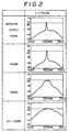
- the wavelength of the semiconductor laser source was set to 1.552 ⁇ m and a 1,000-km transmission experiment using a stage optical amplifier repeater was conducted using, for the optical fibers 101, 111, 121, 131, ... and 191, a dispersion shifted fiber of 100 km whose zero dispersion wavelength was 1.552 ⁇ m.
- the transmission loss of the dispersion shifted fiber per 100 km was 22 to 23 dB
- the noise figures of the optical power amplifier 11, the optical amplifier repeaters 12, 13, 14, 15, ... and 20 and the optical preamplifier 21 were 8 to 9 dB.
- FIG. 2 shows the reception signal spectra. It can be seen that when the transmission signal light level is raised, the signal-to-noise ratio of the signal light level is degraded conversely due to a non-linear effect in the optical fiber.
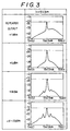
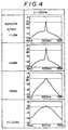
- the same experiment was conducted with the same transmission system as that of FIG. 1 changing the 1.552 ⁇ m wavelength of the semiconductor laser source to 1.547 ⁇ m and 1.557 ⁇ m.
- Observation of the reception spectra after transmission line revealed that, as can be seen in FIGS. 3 and 4, the signal-to-noise ratio after transmission is improved at each of the anomalous (D > 0) and normal (D ⁇ 0) dispersion values.
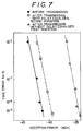
- the amount of dispersion of the entire transmission line was great, the waveform distortion after transmission was too great to receive the signal.
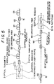
- the wavelength of a semiconductor laser source 1 is set to 1.547 ⁇ m, and optical fibers 101, 111, 121, 131, ... and 192 of a transmission line are constituted from dispersion shifted fibers whose zero dispersion wavelength is 1.552 ⁇ m.
- Conventional fibers 102, 112, 122, 132, ... and 192 which have anomalous dispersion (D > 0) are inserted after the dispersion shifted fibers 101 to 191 of the individual transmission sections for compensating for the wavelength dispersion of the respective fibers 101 to 191.
- the conventional (D > 0) fibers of about 2 km were arranged in cascade connection to set the total amount dispersion of each section to a value in the proximity of 0 ps/nm.
- the repeater output was higher than +8 dBm, a good transmission characteristic was obtained wherein the reception sensitivity degradation after transmission was approximately 1 dB.
- dispersion compensators of -35 ps/nm were constituted from grating pairs, and the dispersion compensators were built into the optical repeaters, following which a transmission experiment similar to the first embodiment was conducted. In this experiment, a good result of approximately 1 dB was obtained for the amount of deterioration of reception sensitivity after transmission.
- optical fibers for dispersion compensation may be mounted in the optical repeaters in place of the dispersion compensators.
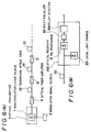
- FIGS. 6(A) and 6(B) Next, the third embodiment of FIGS. 6(A) and 6(B) will be described.
- An optical transmitter 3 drives the current to be supplied to a semiconductor laser source 1 with an electric signal of 5 Gbit/s outputted from a modulation signal source 5 and outputs a CPFSK (Continuous-Phase Frequency-Shift-Keying) optical signal modulation light waveform.
- the CPFSK modulated optical signal is amplified to +6 dBm by a first erbium-doped optical fiber amplifier 11 and outputted to a first transmission optical fiber 101.
- the transmission line optical fiber 101 is an optical fiber of 100 km which has a normal dispersion (D ⁇ 0) amount of -0.4 ps/km/nm and a loss of 21 dB at an oscillation wavelength of 1.552 ⁇ m of the semiconductor laser source 1.
- the signal transmitted through the transmission line optical fiber 101 is again amplified to +6 dBm by a second erbium-doped optical fiber amplifier 12 and outputted to a second transmission line optical fiber 111.
- the output light of the optical fiber 111 is amplified by a third optical amplifier repeater 13 and outputted to a third transmission line 121.
- an optical amplifier lumped repeater system of 100 stages having a total distance of 10,000 km is constructed.
- an optical fiber of 100 km of normal (D ⁇ 0) dispersion similar to optical fiber 101 is employed for transmission optical fibers 111, 121, ...
- An optical receiver 200 mixes the signal light that has passed the last optical transmission line 191 with the output of a local oscillation light source 201 having a frequency that differs from that of the semiconductor laser source 1 by 10 GHz and detects the mixture signal by heterodyne detection by a PIN photodiode 51, which is a photoelectric transducer.
- the heterodyne-detected signal is passed through a delay detector 300 to reproduce it as an electric signal of 5 Gbit/s.
- a delay equalizer 301 shown in FIG. 6(B) is not used.
- the dispersion of the transmission optical fibers is not limited to -0.4 ps/km/nm, and an optical fiber having a normal (D ⁇ 0) or anomalous (D > 0) dispersion region other than that value may be employed. It is to be noted, however, that taking the distribution of dispersion values in the longitudinal direction of the optical fibers, it is effective to set the dispersion to a value in a somewhat excessively normal (D ⁇ 0) dispersion region in advance so that the zero dispersion of the optical fiber may not occur at the signal light wavelength.
- the present invention may be modified in numerous ways in addition to those described above.
- the number of kinds of optical fibers used for each section is also not limited to two but may be three or more.
- the lengths of anomalous (D > 0) and normal (D ⁇ 0) dispersion optical fibers can be set freely for each section.
- the number of repeating stages is not limited to 10 stages, but may be more or less than 10 stages, including for example 20 or 100 stages.
- the length of each section may be greater or smaller than 100 km, including for example 50 km or 150 km, and the bit rate used may also be higher or lower than 10 Gbit/s, including for example 2.5 Gbit/s, 5 Gbit/s or 20 Gbit/s.
- the modulation system is not limited to intensity modulation but may also be frequency modulation or phase modulation.
- the reception system is not limited to a direct detection system, and a heterodyne detection system may be employed.
- the optical amplifier for use with the optical amplifier lumped repeater system is not limited to an erbium-doped optical fiber amplifier but may be a semiconductor laser amplifier, a praseodymium-doped (Pr+3) optical fiber amplifier or an optical Raman amplifier.
- the wavelength band of the transmission light source is not limited to the 1.5 ⁇ m band, but the 1.3 ⁇ m band may be used instead.
Landscapes
- Physics & Mathematics (AREA)
- Chemical & Material Sciences (AREA)
- Dispersion Chemistry (AREA)
- Electromagnetism (AREA)
- Engineering & Computer Science (AREA)
- Computer Networks & Wireless Communication (AREA)
- Signal Processing (AREA)
- General Physics & Mathematics (AREA)
- Optics & Photonics (AREA)
- Optical Communication System (AREA)
Applications Claiming Priority (5)
| Application Number | Priority Date | Filing Date | Title |
|---|---|---|---|
| JP16233892 | 1992-06-22 | ||
| JP4162338A JPH0821908B2 (ja) | 1992-06-22 | 1992-06-22 | 光通信伝送系 |
| JP4237910A JP2919193B2 (ja) | 1992-09-07 | 1992-09-07 | 光通信伝送系 |
| JP23791092 | 1992-09-07 | ||
| EP93109609A EP0575881B1 (fr) | 1992-06-22 | 1993-06-16 | Système de transmission à communication optique avec compensation de la dispersion chromatique |
Related Parent Applications (1)
| Application Number | Title | Priority Date | Filing Date |
|---|---|---|---|
| EP93109609A Division EP0575881B1 (fr) | 1992-06-22 | 1993-06-16 | Système de transmission à communication optique avec compensation de la dispersion chromatique |
Publications (2)
| Publication Number | Publication Date |
|---|---|
| EP0986198A2 true EP0986198A2 (fr) | 2000-03-15 |
| EP0986198A3 EP0986198A3 (fr) | 2000-03-22 |
Family
ID=26488165
Family Applications (2)
| Application Number | Title | Priority Date | Filing Date |
|---|---|---|---|
| EP93109609A Expired - Lifetime EP0575881B1 (fr) | 1992-06-22 | 1993-06-16 | Système de transmission à communication optique avec compensation de la dispersion chromatique |
| EP99124056A Withdrawn EP0986198A3 (fr) | 1992-06-22 | 1993-06-16 | Répéteur à amplificateur optique et méthode de répéteur optique concentré pour grande distance |
Family Applications Before (1)
| Application Number | Title | Priority Date | Filing Date |
|---|---|---|---|
| EP93109609A Expired - Lifetime EP0575881B1 (fr) | 1992-06-22 | 1993-06-16 | Système de transmission à communication optique avec compensation de la dispersion chromatique |
Country Status (4)
| Country | Link |
|---|---|
| US (2) | US5675429A (fr) |
| EP (2) | EP0575881B1 (fr) |
| AU (1) | AU664449B2 (fr) |
| DE (1) | DE69329570T2 (fr) |
Cited By (2)
| Publication number | Priority date | Publication date | Assignee | Title |
|---|---|---|---|---|
| WO2003056726A1 (fr) * | 2001-12-29 | 2003-07-10 | Huawei Technologies Co., Ltd. | Systeme de transmission optique |
| WO2020024544A1 (fr) * | 2018-08-01 | 2020-02-06 | 武汉光迅科技股份有限公司 | Dispositif et procédé de compensation de dispersion |
Families Citing this family (30)
| Publication number | Priority date | Publication date | Assignee | Title |
|---|---|---|---|---|
| JP3269713B2 (ja) * | 1993-09-03 | 2002-04-02 | 株式会社日立製作所 | 光伝送システム |
| US5539563A (en) * | 1994-05-31 | 1996-07-23 | At&T Corp. | System and method for simultaneously compensating for chromatic dispersion and self phase modulation in optical fibers |
| JP3373333B2 (ja) * | 1994-09-12 | 2003-02-04 | Kddi株式会社 | 光増幅中継伝送システム |
| EP1841022A3 (fr) * | 1995-03-20 | 2009-12-02 | Fujitsu Limited | Appareil et procédé pour le traitement d'un signal optique |
| GB9524203D0 (en) * | 1995-11-27 | 1996-01-31 | British Tech Group | Optical communications |
| JP3464867B2 (ja) * | 1996-02-23 | 2003-11-10 | Kddi株式会社 | 光送信装置およびこれを適用した波長多重光送信装置および光伝送システム |
| WO1997034379A1 (fr) * | 1996-03-13 | 1997-09-18 | Hitachi, Ltd. | Systeme de communication optique |
| US6252692B1 (en) * | 1996-06-07 | 2001-06-26 | Nortel Networks Limited | Optical fibre transmission systems |
| US6144474A (en) * | 1996-10-21 | 2000-11-07 | Fujitsu Limited | Optical transmission system including optical repeaters with selectively enabled gain equalizers contained therein and including an add/drop apparatus with a plurality of individually selectable filters |
| US5936754A (en) * | 1996-12-02 | 1999-08-10 | At&T Corp. | Transmission of CDMA signals over an analog optical link |
| FR2757720A1 (fr) * | 1996-12-19 | 1998-06-26 | Alsthom Cge Alcatel | Procede de fabrication d'un dispositif d'adaptation pour liaison de communication optique |
| JPH10242909A (ja) | 1997-02-27 | 1998-09-11 | Fujitsu Ltd | 光伝送システム |
| JP3748652B2 (ja) | 1997-02-27 | 2006-02-22 | 富士通株式会社 | インラインアンプを用いた光伝送システム |
| JPH1155181A (ja) * | 1997-07-31 | 1999-02-26 | Kokusai Denshin Denwa Co Ltd <Kdd> | 波長多重光伝送システム |
| US6005997A (en) * | 1997-12-31 | 1999-12-21 | Mci Communications Corporation | Long-haul terrestrial optical fiber link having low-power optical line amplifiers with integrated dispersion compensation modules |
| CA2319044A1 (fr) | 1998-03-25 | 1999-10-21 | John E. Bowerman | Reseau de transmission optique dote d'un amplificateur a gain divise et d'un dispositif de modification du signal |
| US6115174A (en) | 1998-07-21 | 2000-09-05 | Corvis Corporation | Optical signal varying devices |
| FR2788394B1 (fr) * | 1999-01-11 | 2001-03-30 | France Telecom | Systemes de transmission par fibres optiques |
| CN1168236C (zh) | 1998-12-18 | 2004-09-22 | 皮雷利·卡维系统有限公司 | 在光传输线上发送信号的方法以及光通信系统 |
| JP2000236297A (ja) * | 1999-02-16 | 2000-08-29 | Fujitsu Ltd | 分散補償が適用される光伝送のための方法及びシステム |
| FR2800219B1 (fr) | 1999-10-22 | 2006-06-30 | Algety Telecom | Procede d'ajustement de puissance pour un systeme de transmission optique a multiplexage en longueur d'onde |
| FR2800218B1 (fr) | 1999-10-22 | 2002-01-11 | Algety Telecom | Systeme de transmission par fibre optique utilisant des impulsions rz |
| US7027698B2 (en) * | 2000-03-03 | 2006-04-11 | Pirelli Cavi E Sistemi S.P.A. | Optical fiber for WDM transmission |
| JP3558124B2 (ja) * | 2000-07-25 | 2004-08-25 | 住友電気工業株式会社 | ラマン増幅器及びそれを用いた光伝送システム |
| CA2340848A1 (fr) * | 2001-03-15 | 2002-09-15 | John D. Mcnicol | Gestion de dispersion pour reseaux optiques a haute vitesse de grande portee |
| US20020170591A1 (en) * | 2001-05-15 | 2002-11-21 | Pharmaseq, Inc. | Method and apparatus for powering circuitry with on-chip solar cells within a common substrate |
| JP2003262745A (ja) * | 2002-03-07 | 2003-09-19 | Sumitomo Electric Ind Ltd | 分散補償用ファイバモジュール、分散補償モジュールおよび光通信システム |
| US7277647B2 (en) * | 2002-03-14 | 2007-10-02 | Lucent Technologies Inc. | System and method of optical transmission |
| JP5376055B2 (ja) * | 2010-05-27 | 2013-12-25 | 富士通株式会社 | 光伝送ネットワークシステム、光信号の伝送経路の選択方法、および光伝送装置 |
| US9422801B2 (en) * | 2013-07-19 | 2016-08-23 | Halliburton Energy Services, Inc. | Modulated opto-acoustic converter |
Family Cites Families (10)
| Publication number | Priority date | Publication date | Assignee | Title |
|---|---|---|---|---|
| JPS6265530A (ja) * | 1985-09-17 | 1987-03-24 | Hitachi Cable Ltd | 光伝送系 |
| JPS6265529A (ja) * | 1985-09-17 | 1987-03-24 | Hitachi Cable Ltd | 光通信システムにおける分散補償法 |
| EP0430230B1 (fr) * | 1989-11-30 | 1995-03-15 | Nec Corporation | Appareil de transmission optique |
| JP2839105B2 (ja) * | 1990-01-24 | 1998-12-16 | 国際電信電話株式会社 | 長距離用高速光通信方式 |
| IT1250198B (it) * | 1991-07-04 | 1995-04-03 | Cselt Centro Studi Lab Telecom | Sistema di comunicazione ottica coerente a modulazione di polarizzazione |
| US5261016A (en) * | 1991-09-26 | 1993-11-09 | At&T Bell Laboratories | Chromatic dispersion compensated optical fiber communication system |
| US5191631A (en) * | 1991-12-19 | 1993-03-02 | At&T Bell Laboratories | Hybrid optical fiber and method of increasing the effective area of optical transmission using same |
| US5361319A (en) * | 1992-02-04 | 1994-11-01 | Corning Incorporated | Dispersion compensating devices and systems |
| US5218662A (en) * | 1992-05-06 | 1993-06-08 | Alcatel Network Systems, Inc. | Fiber-optic cable system and method for dispersion compensation at nodes between end points |
| US5224183A (en) * | 1992-07-23 | 1993-06-29 | Alcatel Network Systems, Inc. | Multiple wavelength division multiplexing signal compensation system and method using same |
-
1993
- 1993-06-09 AU AU40170/93A patent/AU664449B2/en not_active Ceased
- 1993-06-16 DE DE69329570T patent/DE69329570T2/de not_active Expired - Lifetime
- 1993-06-16 EP EP93109609A patent/EP0575881B1/fr not_active Expired - Lifetime
- 1993-06-16 EP EP99124056A patent/EP0986198A3/fr not_active Withdrawn
-
1995
- 1995-05-30 US US08/452,728 patent/US5675429A/en not_active Ceased
-
1999
- 1999-10-06 US US09/413,827 patent/USRE37621E1/en not_active Expired - Lifetime
Cited By (2)
| Publication number | Priority date | Publication date | Assignee | Title |
|---|---|---|---|---|
| WO2003056726A1 (fr) * | 2001-12-29 | 2003-07-10 | Huawei Technologies Co., Ltd. | Systeme de transmission optique |
| WO2020024544A1 (fr) * | 2018-08-01 | 2020-02-06 | 武汉光迅科技股份有限公司 | Dispositif et procédé de compensation de dispersion |
Also Published As
| Publication number | Publication date |
|---|---|
| EP0575881B1 (fr) | 2000-10-18 |
| EP0575881A1 (fr) | 1993-12-29 |
| USRE37621E1 (en) | 2002-04-02 |
| US5675429A (en) | 1997-10-07 |
| AU4017093A (en) | 1993-12-23 |
| DE69329570T2 (de) | 2001-03-01 |
| EP0986198A3 (fr) | 2000-03-22 |
| DE69329570D1 (de) | 2000-11-23 |
| AU664449B2 (en) | 1995-11-16 |
Similar Documents
| Publication | Publication Date | Title |
|---|---|---|
| US5675429A (en) | Optical communication transmission system | |
| US6366728B1 (en) | Composite optical fiber transmission line method | |
| US6021245A (en) | Method and optical transmission system for compensating dispersion in optical transmission paths | |
| JP3516409B2 (ja) | 波長分割多重光導波路システム | |
| US7263296B2 (en) | Optical transmission system using in-line amplifiers | |
| US6191854B1 (en) | Optical telecommunications system | |
| US5675428A (en) | Optical communication apparatus | |
| JPH07154327A (ja) | 光通信方法および光通信システム | |
| US6529315B2 (en) | Optical amplifier providing dispersion compensation | |
| JP2743972B2 (ja) | 光増幅中継伝送方法およびシステム装置 | |
| US7034991B2 (en) | Optical amplification and transmission system | |
| US5978122A (en) | Noise suppression method for wavelength division multiplexing transmission system | |
| US20050157378A1 (en) | Reduced four-wave mixing and raman amplification architecture | |
| US6671466B1 (en) | Distortion compensation in optically amplified lightwave communication systems | |
| US20040213577A1 (en) | Optical transmission line and optical transmission system | |
| JP3291370B2 (ja) | 光波長多重伝送方式 | |
| Sugumaran et al. | Optimized FWM Parameters for FTTH Using DWDM Network | |
| US20030152387A1 (en) | Method for transmitting multi-level signals through dispersive media | |
| JP2919193B2 (ja) | 光通信伝送系 | |
| US7324721B2 (en) | Optical communication line with dispersion intrachannel nonlinearities management | |
| US20030133652A1 (en) | Method and apparatus for improving performance in noise limited optical transmission systems | |
| US7123841B2 (en) | Optical transmission system | |
| US20040179844A1 (en) | Wavelength-division-multiplexed metro optical network | |
| Kavitha et al. | Mixed fiber optical parametric amplifiers for broadband optical communication systems with reduced nonlinear effects | |
| JP3609008B2 (ja) | 光伝送路 |
Legal Events
| Date | Code | Title | Description |
|---|---|---|---|
| PUAI | Public reference made under article 153(3) epc to a published international application that has entered the european phase |
Free format text: ORIGINAL CODE: 0009012 |
|
| PUAL | Search report despatched |
Free format text: ORIGINAL CODE: 0009013 |
|
| AC | Divisional application: reference to earlier application |
Ref document number: 575881 Country of ref document: EP |
|
| AK | Designated contracting states |
Kind code of ref document: A2 Designated state(s): DE FR GB |
|
| AK | Designated contracting states |
Kind code of ref document: A3 Designated state(s): AT BE CH DE DK ES FR GB GR IE IT LI LU MC NL PT SE |
|
| 17P | Request for examination filed |
Effective date: 20000224 |
|
| AKX | Designation fees paid |
Free format text: DE FR GB |
|
| 17Q | First examination report despatched |
Effective date: 20071120 |
|
| STAA | Information on the status of an ep patent application or granted ep patent |
Free format text: STATUS: THE APPLICATION IS DEEMED TO BE WITHDRAWN |
|
| 18D | Application deemed to be withdrawn |
Effective date: 20100323 |