EP0986214A2 - Procédé de commande de communication et dispositif de transmission - Google Patents
Procédé de commande de communication et dispositif de transmission Download PDFInfo
- Publication number
- EP0986214A2 EP0986214A2 EP99307186A EP99307186A EP0986214A2 EP 0986214 A2 EP0986214 A2 EP 0986214A2 EP 99307186 A EP99307186 A EP 99307186A EP 99307186 A EP99307186 A EP 99307186A EP 0986214 A2 EP0986214 A2 EP 0986214A2
- Authority
- EP
- European Patent Office
- Prior art keywords
- communication
- station
- transmission
- stations
- control
- Prior art date
- Legal status (The legal status is an assumption and is not a legal conclusion. Google has not performed a legal analysis and makes no representation as to the accuracy of the status listed.)
- Withdrawn
Links
Images


Classifications
-
- H—ELECTRICITY
- H04—ELECTRIC COMMUNICATION TECHNIQUE
- H04W—WIRELESS COMMUNICATION NETWORKS
- H04W74/00—Wireless channel access
- H04W74/002—Transmission of channel access control information
-
- H—ELECTRICITY
- H04—ELECTRIC COMMUNICATION TECHNIQUE
- H04L—TRANSMISSION OF DIGITAL INFORMATION, e.g. TELEGRAPHIC COMMUNICATION
- H04L12/00—Data switching networks
- H04L12/28—Data switching networks characterised by path configuration, e.g. LAN [Local Area Networks] or WAN [Wide Area Networks]
- H04L12/40—Bus networks
- H04L12/40052—High-speed IEEE 1394 serial bus
-
- H—ELECTRICITY
- H04—ELECTRIC COMMUNICATION TECHNIQUE
- H04W—WIRELESS COMMUNICATION NETWORKS
- H04W88/00—Devices specially adapted for wireless communication networks, e.g. terminals, base stations or access point devices
- H04W88/02—Terminal devices
- H04W88/04—Terminal devices adapted for relaying to or from another terminal or user
Definitions
- the present invention relates to a communication control method preferably applied to a case where various information is transmitted by means of a wireless signal, for example, to construct a local area network (LAN) among a plurality of devices, and a transmission apparatus using this control method.
- a wireless signal for example, to construct a local area network (LAN) among a plurality of devices, and a transmission apparatus using this control method.
- LAN local area network
- a wireless signal transmitter/receiver (a wireless transmission apparatus) is connected to each apparatus so as to enable data transmission through wireless transmission, instead of direct connection among apparatuses via a signal line.
- a local area network is constructed through wireless transmission, thereby making it possible to simplify a system configuration without requiring direct connection among apparatus via a signal line or the like.
- a conventionally known access control method for example, in a small scale wireless network, there is exemplified a method for integrally managing communication among transmission apparatuses (nodes) in the network by means of a transmission apparatus (a route node) serving as a central part using a start-type connection.
- a transmission apparatus serving as a central control station performing processing for transmission control is capable of performing wireless communication directly with all other transmission apparatuses in a network system. Therefore, there has been a problem that a wireless communication network construction range is limited within the range capable of directly making communication with the central control station; and the thus constructed network is available in a limited range, which depends on a transmission output of an electric wave of the central control station.
- a distributed network configuration in which communication is made only between stations capable of performing direct communication instead of predetermination of the central control station.
- this distributed network if a distance to a necessary destination station is distant, it is required to transmit data by relaying a number of stations. Every time such relaying is performed, it is required to perform processing for transmission start with the destination station for communication. As a result, there is a problem that data transmission is delayed every time the number of steps performing relaying is increased.
- a communication control method comprising:
- a communication control method for controlling an access of wireless communication among a plurality of communication stations by means of a control station comprising:
- the control station recognizes the presence of a station incapable of directly making wireless communication, and the control station can take action to execute communication control processing for the station.
- a transmission apparatus comprising:
- the common information in the management data received by the receiving means can be transmitted from transmitting means to other transmission apparatuses.
- a transmission apparatus comprising:
- this transmission apparatus the presence of a transmission apparatus incapable of directly making communication with the control apparatus is recognized, making it possible to handle the transmission apparatus.
- the present invention is applied to a network system constructed as a system for transmitting and receiving video data, voice data, computer-use data or the like at, for example, home or in a relatively small station or the like.
- a system configuration of this embodiment will be described with reference to FIG. 1.
- the maximum number of wireless transmission apparatuses configuring the network is predetermined. For example, a maximum of 16 wireless transmission apparatuses are available to construct the network.
- FIG. 1 shows a state in which eight wireless transmission apparatuses 1 to 7 and 10 are allocated. To each of these transmission apparatuses 1 to 7 and 10, antennas 1a to 7a and 10a are respectively connected to perform transmission and receiving.
- each of the wireless transmission apparatuses 1 to 7 and 10 various processing apparatus (not shown) such as a video signal reproducing apparatus, a monitor apparatus, a computer machine, a printer apparatus and so on are individually connected. In the case where data transmission is required among these processing apparatus, data is transmitted via a connected wireless transmission apparatus.
- the eight wireless transmission apparatuses 1 to 7 and 10 each function as a node that is a communication stations, and each apparatus is assigned an identification number ID individually in advance. That is, the transmission apparatus 1C is assigned #0 as its identification numbers ID, and the transmission apparatuses 1 to 7 are assigned identification numbers ID from #1 to #7 in order.
- a system configuration is such that an arbitrary one wireless transmission apparatus in the network system is set as a route node that functions as a central control station, and wireless communication among nodes is executed by means of polling control from the control station.
- this control station uses a wireless transmission apparatus allocated at a position capable of directly making wireless communication with all other communication stations in the system.
- the wireless transmission apparatus 10 whose identification number ID is #0, allocated at a substantial center in the network system is defined as a central control station.
- a so-called start-type connection configuration is such that other peripheral communication stations are controlled from this central route node.
- "communication stations" which is merely referred to as, is inclusive of a central control station.
- the wireless transmission apparatus 7 whose identification number ID is #7 is arranged at a position incapable of directly making wireless communication with the wireless transmission apparatus 10 that is a central control station thereof.
- the wireless transmission apparatus 7 is arranged at a position capable of directly making communication between the wireless transmission apparatuses 3 and 6 whose identification numbers IDs are #3 and #6, respectively.
- FIG. 2 is a view showing a physical topology map that present a communication state between stations when each communication station and the control station in this embodiment are arranged, wherein direct communication is enabled between connected communication stations indicated by the arrow.
- communication stations 1 to 7 and 10 each capable of directly making communication with adjacently positioned communication stations.
- the communication station 1 whose identification number ID is #1 is capable of directly making communication with the communication stations 2, 4, and 10 whose identification number IDs are #2, #4, and #0, which are arranged at the periphery of communication station 1.
- a communication station (a control station) arranged at a substantial center is capable of directly making communication with all of communication stations 1 to 6 other than communication station 7 whose identification number ID is #7.
- transmission processing is performed by other communication stations by relaying transmission data.
- FIG. 3 there is shown a configuration example of the wireless transmission apparatuses 1 to 7 and 10 each configuring communication stations.
- the wireless transmission apparatuses 1 to 7 and 10 each are commonly configured (except that only an control configuration adopted to function as a central control station differs from other communication stations).
- These apparatus each are provided with an antenna 21 and a wireless processing unit 22 connected to the antenna 21, the wireless processing unit performing wireless transmission processing and wireless receiving processing, and is configured to enable wireless transmission with other transmission apparatuses.
- a transmission system in which transmission and receiving are performed at the wireless processing unit 22 of this embodiment for example, a transmission system using a multi-carrier signal called an OFDM (Orthogonal Frequency Division Multiples) is applied.
- OFDM Orthogonal Frequency Division Multiples
- a frequency used for transmission and receiving for example, a very high frequency band (for example 5 GHz band) is used.
- a relatively weak transmission output is set.
- an output capable of wireless transmission in a relatively short distance from several meters to several tens of meters.
- a data conversion unit 23 for performing data conversion of a signal received at the wireless processing unit 22 and data conversion of a signal to be transmitted at the wireless processing unit 22.
- the converted data at the data conversion unit 23 is supplied to a connected processor via an interface unit 24, and data to be supplied from the connected processing unit is supplied to the data conversion unit 23 via the interface unit 24, thereby enabling conversion processing.
- Each unit in the wireless transmission apparatus is configured to execute processing based on control of a control unit 25 configured by micro-computers or the like.
- the wireless processing unit 22 receives a control signal
- the received control signal is supplied to the control unit 25 via the data conversion unit 23, and the control unit 25 sets each unit in a state indicated by the received control signal.
- a control signal to be transmitted from the control unit 25 to other transmission apparatus is supplied from the control unit 25 to the wireless processing unit 22 via the data conversion unit 23, thereby causing its wireless transmission.
- the control unit 25 is constructed to judge a receiving timing of that synchronous signal, set a frame period based on the synchronous signal, and execute communication control processing at that frame period.
- an internal memory 26 is connected to the control unit 25 so that data required for communication control is temporarily stored in the internal memory 26.
- FIG. 4 shows a configuration of a signal to be transmitted among communication stations (wireless transmission apparatuses 1 to 7 and 10) in the network system of this embodiment.
- the network system is configured such that a frame period is specified, and data is transmitted. That is, as shown in FIG. 4, a predetermined single-frame interval is specified, a predetermined interval at the head portion of the single-frame interval is defined as a management information transmission region, and a management information broadcasting interval and a local synchronous transmission and receiving interval are set in the management information transmission region.
- an interval other than the management information transmission region of each frame is defined as a media information transmission region. In this media information transmission region, various data is transmitted by means of polling control or the like.
- management information common to the system is transmitted from the central control station 10.
- the management information to be transmitted includes, for example, synchronous data required to obtain frame synchronism in the network system; identification number data specific to the network system; and data of topology map in the network or the like.
- a predetermined number of slots (16 in this case) are set at an equal interval, and 16 slots in such one frame are allocated respectively to 16 communication stations in this network system.
- These allocated slots include, for example, a slot for communication station whose identification number ID is #0; a slot for communication station whose identification number ID is #1; a slot for communication station whose identification number ID is #2; ⁇ a slot for communication station whose identification number ID is #15 in an ascending order.
- the allocated slots for communication stations each are constructed to transmit a local synchronous signal from communication station corresponding to the slot.
- the network system is composed of eight communication stations, eight slots (eight slots from the head) are used, and the remaining slots are not used (i.e., data is not transmitted to the remaining slots).
- the data of identification number ID assigned to each communication station is supplied to the local synchronous signal.
- the signal includes data concerning the communication station capable of being received at that station (data produced based on the receiving state of the local synchronous signal before one frame) or the like.
- Local synchronous signals to be transmitted in each slot at the local synchronous transmission and receiving interval are received and processed at each communication station in the network system.
- the transmission processing and receiving processing of the local synchronous signal will be described later.
- data transfer (transmission) processing is performed among communication stations based on an access control of the central control station.
- the access control by this central control station is executed by means of polling control from the central control station, for example.
- the communication stations each are called in order from the central control station by means of a polling response request signal, and transmission is sequentially executed for each communication station.
- the communication station of identification number ID specified by the polling response request signal when data to be transmitted is present, data transmission processing is performed immediately after the polling response request signal has been received.
- data transfers in asynchronous (non-synchronizing) transfer mode and isochronous (synchronizing) transfer mode are used depending on type of data to be transmitted.
- the asynchronous transfer mode is used for transmission of relatively short data such as control data; and the isochronous transfer mode is used for transmission of data requiring a real-time transfer such as video data, voice data or the like.
- a system conforming to the IEEE1394 Standard is applicable.
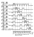
- a to H each shows a communication state at the local synchronous transmission and receiving interval in eight communication stations each.
- A designates the state in communication station 10 that is the central control station
- B to H each designate the state from communication stations 1 to 7 in order.
- the range marked with diagonal line designates as follows: Transmission processing 'Tx' is performed at the wireless processing unit 22 that is transmitting means of that communication station, and wireless transmission is done from the antenna 21.
- the transmitted signal from another communication station is properly received and processed at the wireless processing unit 22 that is a receiving means of the communication station.
- a signal cannot be properly received (i.e., data cannot be decoded correctly by attempting reception).
- transmission processing 'Tx' is performed for a station synchronous signal at an interval of 0th slot, and receiving processing is performed in the other slots (intervals in slot 1 and subsequent).
- receiving processing is performed in the other slots (intervals in slot 1 and subsequent).
- communication stations 1 to 6 allocated in these slots are placed at a position capable of directly making wireless communication with communication station 10, and thus, data included in the receiving signal can be correctly decoded.
- communication station 7 is not placed at a position capable of directly making wireless communication with communication station 10, and data cannot be received at this slot position.
- the station synchronous signal is transmitted at the slot position allocated for each communication station, and receiving processing is performed at the other slot position. That is, in communication station 1 whose identification number ID is #1, as shown by B in FIG. 5, transmission processing 'Tx' is performed for a node synchronous signal in the first slot, and receiving processing is performed in the other slots.
- the communication stations whose positions are adjacent to communication station 1 whose identification number ID is #1 are communication stations 10, 2, and 4 whose identification numbers IDs are #0, #2, and #4.
- communication station 1 as shown by B in FIG.
- transmission processing 'Tx' is performed for the station synchronous signal in the second slot, and receiving processing is performed in the other slots.
- the communication stations at positions adjacent to the communication station 2 are communication stations 10, 1, and 3 whose identification numbers IDs are #0, #1, and #3.
- communication station 2 as shown by C in FIG. 5, only the station synchronous signals to be transmitted from these communication stations to the 0th slot, the first slot and the third slot can be correctly received and processed.
- a transmission state of the station synchronous signals to be transmitted from communication station 2 to the second slot is shown by C in FIG.
- communication station 7 whose identification number IF is #7, as shown by H in FIG. 5, transmission processing 'Tx' is performed for the station synchronous signal in the seventh slot, and receiving processing is performed in the other slots.
- the communication stations whose positions are adjacent to communication station 7 are communication stations 3 and 6 whose identification numbers IDs are #3 and #6.
- communication station 7 as shown by H in FIG. 5, only the station synchronous signals to be transmitted from these stations to the third slot and the sixth slot can be correctly received and processed.
- a transmission state of the station synchronous signal to be transmitted from communication station 7 to the seventh slot is shown by H in FIG.
- communication station 10 that is a central control station cannot receive the station synchronous signal from communication station 7 whose identification number ID is #7, and cannot recognize the presence of communication station 7 directly. Based on information contained in the station synchronous signals from communication stations whose identification numbers IDs are #3 and #6, communication station 10 that is a central control station recognizes the presence of communication station 7 from the station information that can be received at the respective stations.
- communication stations 1 to 6 capable of directly receiving the signal from communication station 10 that is a central control station judge the positions of transmission slots allocated for their own stations based on the receiving timing of the synchronous signal from this communication station 10.
- Communication station 7 incapable of directly receiving the signal from communication station 10 judges the position of transmission slot allocated for its own station based on receiving timing of the station synchronous signal that can be received at that communication station 7. That is, the position of slot 7 allocated for its own station is judged from the positions of the third and sixth slots.
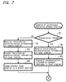
- Each communication station judges whether or not a slot interval that is a transmission timing of its station arrives (step 101); and, if it is not the transmission timing of its own station, receives station synchronization information of other station (step 102). Based on a receiving state of the received local synchronous signals of other station, each communication station creates the station synchronization information to be transmitted from its own station (step 103). Then, based on the received station synchronization information of the other station, each communication station judges whether its own station is a branch station (step 104).
- each communication station when each communication station can receive the station synchronization information from a communication station incapable of directly receiving the signal from communication station 10 that is a central control station, it judges that its own station is a branch station.
- the communication station which cannot directly receive the signal from communication station 10 that is a central control station is the communication station 7, and communication stations 3 and 6 can directly receive the local synchronous information from this communication station 7.
- the two communication stations 3 and 6 are recognized to be branch stations.
- step 101 when each communication station judges as being a slot interval that is a transmission timing of its own station, it acquires the station synchronization information of its own station which was created in step 103 (in step 105), and wireless-transmits the acquired station synchronization information of its own station on a network (step 106).
- a communication station that is judged to be a branch station in the flow chart of FIG. 7 is constructed to perform retransmission processing for the management information.
- a to H in FIG. 8 each show a communication state at the management information broadcasting interval at eight communication stations.
- a in FIG. 8 show the state in communication station 10 that is a central control station; and B to H in FIG. 8 show the states of communication stations 1 to 7 in order.
- the range marked with slant lines designates as follows: Transmission processing 'Tx' is performed at the wireless processing unit 22 that is transmitting means of the communication station, and wireless transmission is done from the antenna 21.
- the other pulse-shaped rise interval designates a state in which receiving processing 'Rx' of the transmitted management information from other communication stations is performed at the wireless processing unit 22 that is receiving means of the communication station.
- An interval free of a pulse-shaped rise designates a state in which the management information cannot be received.
- a first half of the management information broadcasting interval is defined as a control station notification interval, and a latter half thereof is defined as a relay notification interval.
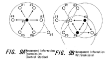
- Communication station 10 whose identification number ID is #0 that is a central control station, as shown by A in FIG. 8, transmits management information common to each station at the control station notification interval.
- A shows a range at which the management information from this communication station 10 arrives.
- the transmitted management information as shown by B to G in FIG. 8, is received at communication stations 1 to 6 capable of directly making communication with communication station 10, and the control unit 25 in each communication station stores the information in the connected internal memory 26.
- communication station 7 that is a hidden terminal station incapable of directly making communication with communication station 10, as shown by H in FIG. 8, management information is not received at this control station notification interval.
- the above mentioned communication station judged to be a branch station during processing in the flow chart in FIG. 7 performs processing for transmitting the received and stored information at the immediately preceding control station notification interval. That is, as shown by D and G in FIG. 8, communication stations 3 and 6 judged to be branch stations for communication station 7 transmits management information.
- FIG. 9, B shows a transmission state of the management information from these communication stations 3 and 6.
- the management information to be transmitted from the communication stations 3 and 6 is received at communication station 7 that is a hidden terminal station, as shown by H in FIG. 8.
- the retransmitted management information is received.
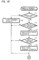
- Each communication station judges whether or not its own station is a central control station (step 111). When its own station is a central control station, each communication station transmits management information in the control station notification interval (step 112). When its own station is judged not to be a central control station, each communication station judges whether or not management information can be received at the control station notification interval (step 113). When the management information cannot be received, each communication station receives and processes the management information in the relay notification interval.
- each communication station acquires branch station information defined at the control unit 25 of its own station.
- the branch station information is information defined based on the judgment in step 104 in the flow chart of FIG. 7.
- each communication station judges whether or not its own station is a branch station, that is, whether or not the station requires relay transmission of management information (step 115). In the case where the station does not require relay transmission of management information, processing concerning the management information in this frame is terminated. In the case where the station requires relay transmission of management information, the management information is subject to transmission processing in the relay notification interval (step 116).
- the management information is transmitted simultaneously at a same frequency from a plurality of communication stations 3 and 6 to communication station 7 whose identification number ID is #7.
- a transmission timing or the like is precisely matched, thereby making it possible for communication station 7 to properly receive and process signals to be transmitted simultaneously from a plurality of stations.
- SFN Single Frequency Network
- Communication station 7 which receives signals to be transmitted simultaneously from a plurality of stations may be configured by applying diversity receiving technology using a plurality of receiving antennas so as to receive a signal from a specified branch station with precedence.
- each communication station configuring a wireless communication network is configured to perform the processing described in this embodiment, thereby making it possible for a central control station to recognize a communication station (a hidden terminal station) incapable of directly making wireless communication with the central control station, and to control such hidden terminal station as a communication station in the network. That is, a central control station can recognize a hidden terminal station by transmitting and receiving the local synchronous signal at each communication station, and can perform broadcasting processing of common management information from the central control station to that hidden terminal station by relay processing of management information at a branch station.
- all communication stations receiving management information at the control station notification interval may cause relay transmission of management information at the relay notification interval. That is, as shown by A in FIG. 11, when the management information common to each station is transmitted from the communication station 10 with the identification number #0 as a central control station at the control station notification interval in the management information broadcasting interval, and communication stations 1 to 6 whose identification numbers IDs are #1 to #6 shown by B to G in FIG. 11 receive the management information, all of the communication stations 1 to 6 receiving the information may be configured to perform transmission processing 'Tx' for the received management information at the relay notification interval. With such configuration, communication station 7 that is a hidden terminal station incapable of making direct communication with the central control station can receive management information at the relay notification interval so shown by H in FIG. 11.
- management information is transmitted from communication station 10 whose identification number ID is #0, as shown by A in FIG. 12.
- the relay notification interval as shown by B in FIG. 12, all stations capable of receiving the signals from communication station 10 serve as branch stations, and management information is relay-transmitted.
- each communication station judges whether or not its own station is a central control station (step 121). When its own station is the central control station, it transmits management information at the control station notification interval (step 122). When its own station is judged not to be a central control station in step 121, each communication station judges whether or not management information can be received in the control station notification interval (step 123). When management information cannot be received, the management information is subject to receiving processing at the relay notification interval. When management information can be received in step 123, the management information is subject to transmission processing at the relay notification interval (step 124).
- this configuration is applicable to a case in which a hidden terminal station moves in the vicinity of the network, for example.
- the management information to be transmitted at the relay notification interval is received, thereby making it to recover such failure.
- FIG. 14 and FIG. 15 each show an example of the state in the above case. For example, as shown by A in FIG. 14.
- management information common to each station is transmitted from communication station 10 whose identification number ID is #0 that is a central control station at the control station notification interval in the management information broadcasting interval
- communication stations 2, 4, and 6 can correctly receive the management information at this time, as shown by B to G in FIG. 14, and communication stations 1, 3, and 5 fail to receive the management information (NG).
- communication stations 2, 4, and 6 correctly receiving management information performs transmission processing 'Tx' for the received management information at the relay notification interval; communication station 7 that is a hidden terminal station as shown by H in FIG. 14 receives management information; and communication stations 1, 3, and 5 receives management information at the relay notification interval.
- management information is transmitted from communication station 10 whose identification number ID is #0 as shown by A in FIG. 15, and is normally received at communication stations 2, 4, and 6.
- management information is relay-transmitted from these communication stations 2, 4, and 6 that have successfully received the information to the other communication stations.
- management information not only can be relay-transmitted to the hidden terminal station, but can be transmitted reliably to each station in the network, and wireless network configuration can be made more reliable.
- an interval for transmitting management information from a central control station and a relay notification interval for relaying the management information are provided in the management information broadcasting interval provided in the management information transmission region in each frame period so that the management information is relay-transmitted from a branch station in the management information transmission region, relay transmission of management information from the branch station may be configured to be performed within another period.
- the received management information at the management information broadcasting interval may be transmitted to a hidden terminal station.
- management information transmission regions are provided in all frames, only one management information transmission region may be provided at every predetermined number of frames, thereby transmitting management information and local synchronization information.
- a frame period is specified based on management information to be transmitted from a central control station or a branch station in the management information transmission region, the frame period may be specified by means of other signals.
- the presence of a so-called hidden terminal station incapable of directly receiving information from a central control station can be recognized in a network, there is no need for limiting the network utility range to a range capable of receiving the signal from the central control station, and the network can be broadened to a wider range.
- station synchronization intervals allocated for each station are provided to grasp the present of a station configuring a network, and a hidden terminal station incapable of directly receiving the signal from a central control station permits information transmission, thereby making it possible to broaden a network configuration.
- a branch station capable of making direct communication is relayed, thereby making it possible to broadcast-transmit network-shared information to be sent from the central control station.
- a branch station capable of communicating with a control station
- a relay station is specified as a relay station, thereby making it possible to transit information.
- a mobile range can be broadened to a wider range by applying to a control of a network containing a mobile station.
- network connection can be ensured through a branch station, thus making it possible to facilitate control.
Landscapes
- Engineering & Computer Science (AREA)
- Computer Networks & Wireless Communication (AREA)
- Signal Processing (AREA)
- Mobile Radio Communication Systems (AREA)
- Small-Scale Networks (AREA)
Applications Claiming Priority (2)
| Application Number | Priority Date | Filing Date | Title |
|---|---|---|---|
| JP10258855A JP2000092076A (ja) | 1998-09-11 | 1998-09-11 | 通信制御方法及び伝送装置 |
| JP25885598 | 1998-09-11 |
Publications (2)
| Publication Number | Publication Date |
|---|---|
| EP0986214A2 true EP0986214A2 (fr) | 2000-03-15 |
| EP0986214A3 EP0986214A3 (fr) | 2004-01-02 |
Family
ID=17325980
Family Applications (1)
| Application Number | Title | Priority Date | Filing Date |
|---|---|---|---|
| EP99307186A Withdrawn EP0986214A3 (fr) | 1998-09-11 | 1999-09-10 | Procédé de commande de communication et dispositif de transmission |
Country Status (3)
| Country | Link |
|---|---|
| US (1) | US6542494B1 (fr) |
| EP (1) | EP0986214A3 (fr) |
| JP (1) | JP2000092076A (fr) |
Cited By (3)
| Publication number | Priority date | Publication date | Assignee | Title |
|---|---|---|---|---|
| EP1137304A3 (fr) * | 2000-03-23 | 2003-02-05 | Sony Corporation | Méthode de transmission radio et dispositif |
| EP1969771A4 (fr) * | 2006-01-05 | 2012-10-03 | Samsung Electronics Co Ltd | Procede et dispositif servant a transmettre une trame de controle a un noeud cache dans un reseau local sans fil |
| US20160198436A1 (en) * | 2002-02-05 | 2016-07-07 | Sony Corporation | Wireless communication system and wireless communication control method, wireless communication device and wireless communication method, and computer program |
Families Citing this family (14)
| Publication number | Priority date | Publication date | Assignee | Title |
|---|---|---|---|---|
| JP4192328B2 (ja) * | 1999-03-24 | 2008-12-10 | ソニー株式会社 | 無線伝送方法及び無線伝送装置 |
| JP3796537B2 (ja) | 2000-10-24 | 2006-07-12 | 独立行政法人情報通信研究機構 | 無線通信端末、無線通信方法、および、情報記録媒体 |
| KR100752947B1 (ko) * | 2003-06-06 | 2007-08-30 | 메시네트웍스, 인코포레이티드 | 빌딩들 내부의 무선 디바이스들의 위치를 정확하게연산하기 위한 mac 프로토콜 |
| JP4678859B2 (ja) * | 2006-01-12 | 2011-04-27 | キヤノン株式会社 | 通信装置及びその制御方法 |
| WO2008078394A1 (fr) * | 2006-12-26 | 2008-07-03 | Fujitsu Limited | Procédé de communication sans fil, station de contrôle sans fil et station de base sans fil |
| WO2008136106A1 (fr) | 2007-04-25 | 2008-11-13 | Fujitsu Limited | Système de radiocommunication mobile ayant une fonction de partage des ressources radio |
| US8180352B2 (en) * | 2007-08-15 | 2012-05-15 | Oracle America, Inc. | Topology controlled discovery for next hop determination |
| JP5185024B2 (ja) * | 2008-08-28 | 2013-04-17 | キヤノン株式会社 | 通信システム及びその従属局並びに中継伝送方法 |
| US9548854B2 (en) | 2012-04-13 | 2017-01-17 | Dominant Technologies, LLC | Combined in-ear speaker and microphone for radio communication |
| US10568155B2 (en) | 2012-04-13 | 2020-02-18 | Dominant Technologies, LLC | Communication and data handling in a mesh network using duplex radios |
| US9143309B2 (en) | 2012-04-13 | 2015-09-22 | Dominant Technologies, LLC | Hopping master in wireless conference |
| US10136426B2 (en) | 2014-12-05 | 2018-11-20 | Dominant Technologies, LLC | Wireless conferencing system using narrow-band channels |
| CN107005394B (zh) | 2014-12-05 | 2019-08-06 | 主导技术有限公司 | 一种建立直接全双工通信的通信系统、移动设备和方法 |
| EP3952550A1 (fr) * | 2019-03-28 | 2022-02-09 | Ntt Docomo, Inc. | Terminal utilisateur et procédé de communication sans fil |
Family Cites Families (13)
| Publication number | Priority date | Publication date | Assignee | Title |
|---|---|---|---|---|
| US5477541A (en) * | 1989-09-29 | 1995-12-19 | White; Richard E. | Addressing technique for storing and referencing packet data |
| US5128934A (en) * | 1990-06-29 | 1992-07-07 | Motorola, Inc. | Multiple transmitter message transmission system and method therefor |
| JP2887815B2 (ja) * | 1990-08-08 | 1999-05-10 | アイシン精機株式会社 | 移動局位置モニタリングシステム |
| US5612948A (en) * | 1994-11-18 | 1997-03-18 | Motorola, Inc. | High bandwidth communication network and method |
| SE514987C2 (sv) * | 1995-03-30 | 2001-05-28 | Telia Ab | Förfarande och anordning vid ett telesystem för HIPERLAN- överföring |
| US5857144A (en) * | 1996-08-09 | 1999-01-05 | Ericsson, Inc. | In-band vehicular repeater for trunked radio system |
| US5740363A (en) * | 1996-11-26 | 1998-04-14 | Texas Instruments Incorporated | Method and apparatus for low power communications between mobile computing devices |
| GB2320661B (en) * | 1996-12-20 | 2001-10-03 | Dsc Telecom Lp | Processing data transmitted and received over a wireless link connecting a central terminal and a subscriber terminal of a wireless telecommunications system |
| US6175550B1 (en) * | 1997-04-01 | 2001-01-16 | Lucent Technologies, Inc. | Orthogonal frequency division multiplexing system with dynamically scalable operating parameters and method thereof |
| JP3141820B2 (ja) * | 1997-07-18 | 2001-03-07 | 日本電気株式会社 | アドホックローカルエリアネットワーク |
| US6141533A (en) * | 1997-11-13 | 2000-10-31 | Motorola, Inc. | Method and apparatus for a mobile repeater |
| US6192026B1 (en) * | 1998-02-06 | 2001-02-20 | Cisco Systems, Inc. | Medium access control protocol for OFDM wireless networks |
| US6359877B1 (en) * | 1998-07-21 | 2002-03-19 | Telefonaktiebolaget Lm Ericsson (Publ) | Method and apparatus for minimizing overhead in a communication system |
-
1998
- 1998-09-11 JP JP10258855A patent/JP2000092076A/ja active Pending
-
1999
- 1999-09-09 US US09/392,739 patent/US6542494B1/en not_active Expired - Lifetime
- 1999-09-10 EP EP99307186A patent/EP0986214A3/fr not_active Withdrawn
Cited By (9)
| Publication number | Priority date | Publication date | Assignee | Title |
|---|---|---|---|---|
| EP1137304A3 (fr) * | 2000-03-23 | 2003-02-05 | Sony Corporation | Méthode de transmission radio et dispositif |
| US6961353B2 (en) | 2000-03-23 | 2005-11-01 | Sony Corporation | Radio transmission method and radio transmission apparatus |
| US20160198436A1 (en) * | 2002-02-05 | 2016-07-07 | Sony Corporation | Wireless communication system and wireless communication control method, wireless communication device and wireless communication method, and computer program |
| US10397899B2 (en) * | 2002-02-05 | 2019-08-27 | Sony Corporation | Wireless communication system and wireless communication control method, wireless communication device and wireless communication method, and computer program |
| US11229010B2 (en) | 2002-02-05 | 2022-01-18 | Sony Corporation | Wireless communication system and wireless communication control method, wireless communication device and wireless communication method, and computer program |
| EP1969771A4 (fr) * | 2006-01-05 | 2012-10-03 | Samsung Electronics Co Ltd | Procede et dispositif servant a transmettre une trame de controle a un noeud cache dans un reseau local sans fil |
| EP2595443A1 (fr) * | 2006-01-05 | 2013-05-22 | Samsung Electronics Co., Ltd. | Procédé et appareil de transmission de trame de commande vers un nýud caché dans un réseau local sans fil |
| EP3288331A1 (fr) * | 2006-01-05 | 2018-02-28 | Samsung Electronics Co., Ltd. | Procédé et appareil de transmission de trame de commande vers un noud caché dans un réseau local sans fil |
| USRE47579E1 (en) | 2006-01-05 | 2019-08-20 | Sisvel International S.A. | Method and apparatus for transmitting control frame to hidden node in wireless LAN |
Also Published As
| Publication number | Publication date |
|---|---|
| JP2000092076A (ja) | 2000-03-31 |
| EP0986214A3 (fr) | 2004-01-02 |
| US6542494B1 (en) | 2003-04-01 |
Similar Documents
| Publication | Publication Date | Title |
|---|---|---|
| US6542494B1 (en) | Communication control method and transmission apparatus | |
| US9635688B2 (en) | Communication system, a communication method, and a communication apparatus | |
| US6493545B1 (en) | Communication control method and transmission apparatus | |
| US6728231B1 (en) | Radio transmission method and radio transmission | |
| KR100655947B1 (ko) | 전송제어방법 및 전송장치 | |
| JP2002271340A (ja) | 無線lanシステム及び無線lanシステムの信号衝突回避方法 | |
| US6490459B1 (en) | Communication control method and transmission apparatus | |
| US10638532B2 (en) | Method and circuitry for wireless communications between different networks | |
| EP0495600B1 (fr) | Méthode de scrutin dans un système de communication de paquets de données par radio | |
| KR20010062775A (ko) | 무선 전송 방법 및 장치 | |
| US6714801B1 (en) | Radio transmission control method and radio transmission device | |
| JP2000069033A (ja) | 無線通信装置 | |
| EP2341742B1 (fr) | Système de relais, dispositif de relais, et procédé de synchronisation | |
| US6992996B2 (en) | Network management method, wireless transmission method and wireless transmission apparatus | |
| JPH11298477A (ja) | 伝送制御方法及び伝送制御装置 | |
| JP2000115182A (ja) | 無線パケット通信方式 | |
| US20010036836A1 (en) | Radio transmission method and radio transmission apparatus | |
| JPS58215146A (ja) | ロ−カル・ネツトワ−ク通信方式 | |
| KR20070021096A (ko) | 미니 슬롯 통신 프로토콜 | |
| JP2001257691A (ja) | 無線伝送方法および無線伝送装置 | |
| JP2002044102A (ja) | 無線伝送方法及び無線伝送装置 | |
| JPH09162803A (ja) | デジタル移動通信における同報ファクシミリ通信方法 |
Legal Events
| Date | Code | Title | Description |
|---|---|---|---|
| PUAI | Public reference made under article 153(3) epc to a published international application that has entered the european phase |
Free format text: ORIGINAL CODE: 0009012 |
|
| AK | Designated contracting states |
Kind code of ref document: A2 Designated state(s): AT BE CH CY DE DK ES FI FR GB GR IE IT LI LU MC NL PT SE |
|
| AX | Request for extension of the european patent |
Free format text: AL;LT;LV;MK;RO;SI |
|
| PUAL | Search report despatched |
Free format text: ORIGINAL CODE: 0009013 |
|
| AK | Designated contracting states |
Kind code of ref document: A3 Designated state(s): AT BE CH CY DE DK ES FI FR GB GR IE IT LI LU MC NL PT SE |
|
| AX | Request for extension of the european patent |
Extension state: AL LT LV MK RO SI |
|
| AKX | Designation fees paid | ||
| REG | Reference to a national code |
Ref country code: DE Ref legal event code: 8566 |
|
| STAA | Information on the status of an ep patent application or granted ep patent |
Free format text: STATUS: THE APPLICATION IS DEEMED TO BE WITHDRAWN |
|
| 18D | Application deemed to be withdrawn |
Effective date: 20040705 |