EP0986520B1 - Silo für schlämme - Google Patents
Silo für schlämme Download PDFInfo
- Publication number
- EP0986520B1 EP0986520B1 EP98924283A EP98924283A EP0986520B1 EP 0986520 B1 EP0986520 B1 EP 0986520B1 EP 98924283 A EP98924283 A EP 98924283A EP 98924283 A EP98924283 A EP 98924283A EP 0986520 B1 EP0986520 B1 EP 0986520B1
- Authority
- EP
- European Patent Office
- Prior art keywords
- sieve
- grate
- silo
- sludge
- foreign body
- Prior art date
- Legal status (The legal status is an assumption and is not a legal conclusion. Google has not performed a legal analysis and makes no representation as to the accuracy of the status listed.)
- Expired - Lifetime
Links
- 239000010802 sludge Substances 0.000 title claims description 45
- 239000010801 sewage sludge Substances 0.000 claims description 11
- XLYOFNOQVPJJNP-UHFFFAOYSA-N water Substances O XLYOFNOQVPJJNP-UHFFFAOYSA-N 0.000 claims description 3
- 206010070245 Foreign body Diseases 0.000 claims 3
- 239000010865 sewage Substances 0.000 claims 1
- 238000000926 separation method Methods 0.000 description 6
- 239000007787 solid Substances 0.000 description 4
- 238000004140 cleaning Methods 0.000 description 1
- 230000001143 conditioned effect Effects 0.000 description 1
- 238000011161 development Methods 0.000 description 1
- 230000018109 developmental process Effects 0.000 description 1
- 238000006073 displacement reaction Methods 0.000 description 1
- 238000009434 installation Methods 0.000 description 1
- 238000012432 intermediate storage Methods 0.000 description 1
- 238000000034 method Methods 0.000 description 1
- 235000011837 pasties Nutrition 0.000 description 1
- 230000000717 retained effect Effects 0.000 description 1
- 238000012216 screening Methods 0.000 description 1
- 238000007873 sieving Methods 0.000 description 1
Images

Classifications
-
- C—CHEMISTRY; METALLURGY
- C02—TREATMENT OF WATER, WASTE WATER, SEWAGE, OR SLUDGE
- C02F—TREATMENT OF WATER, WASTE WATER, SEWAGE, OR SLUDGE
- C02F11/00—Treatment of sludge; Devices therefor
Definitions
- the invention relates to a silo for sludges, in particular Sewage sludge, with a sludge receiving part and with one arranged above the sludge receiving part, via a large inlet opening with this communicating batch and with an in arranged lower area of the sludge receiving part, preferably connectable to a piping system Schlammaustragvorraum.
- the invention is based on the object Precautions on a silo for sludge and Sludge to meet the installation of maintenance-intensive Screening devices in downstream piping systems and make plants unnecessary.
- the solution according to the invention is based on the idea that with one arranged in the loading section of the silo Separation device for entrained in the sludge Foreign matter from the sludge discharge device Sludge removed from the silo for trouble-free transport better conditioned via a piping system can be.
- sludge like sewage sludge with a solids content of up to 70% Foreign bodies are embedded in the mud and clean cannot be separated from the sludge by sieving, according to a preferred embodiment of the invention suggested that the foreign matter separator a sieve grate spanning the inlet opening and at least one arranged above the sieve grate Has counter surface that under pressure of mud can be moved relative to one another through the sieve grate are.
- the solid-state separator has one bounded by raised sidewalls, with mud loadable loading frame on the so between the sieve grid and the counter surface positioned or positionable is that the sieve grid and / or the counter surface slidable relative to one another transversely to the frame opening are.
- a first embodiment sees here before that the counter surface through the inner surface one of the silo covers spanning the loading section is formed and that the sieve grate by means of a preferably hydraulic drive through the silofest Feed frame through towards the silo cover is movable.
- a sieve grate spanning the inlet opening provided for silofest, while the counter surface on a pressure plate is arranged by means of a preferably hydraulic Drive through the loading frame can be moved from above towards Siebrost.
- a relative Slidable to the loading section and to the sieve grid loading frame open at the top and bottom is provided, in a filling station located next to the sieve grate on a surface aligned with the sieve grid can be loaded with mud and from there towards Sieve grid is movable.
- the loading frame can contaminate residual sludge with the pressure plate raised relative moved towards the sieve grate in the direction of the foreign body outlet become.
- the foreign body outlet points in this case expediently one aligned with the sieve grid at its edge Outlet opening through which the bottom open Loading frame with discharge of the foreign bodies is movable.
- the hydraulic drive of the sieve grate or the pressure plate is preferably carried out by four simultaneously operable, in the corner area of the sieve grate or the pressure plate attacking hydraulic cylinders. Depending on the application can also use more or less hydraulic cylinders than Drive units are used.
- Another advantageous embodiment of the invention provides that the counter surface is inclined by a Scraper surface pointing towards the sieve grid at least a scraper resiliently against the sieve grate is formed, the sieve grate and the scraper parallel to the surface of the screen grate relative to each other are movable. It is advantageous the sieve grid opposite the at least one, silofest arranged scraper rotatable about its central axis. To remove large foreign bodies more easily to the foreign body outlet To be able to transport is according to an advantageous Embodiment of the invention additionally at least a spaced above the sieve grid, radially aligned stop bar for such Foreign body provided, which also serves as a mounting beam can act for the wipers.
- the rotating sieve grate is practical surrounded by a silage-proof jacket that at least has an opening forming the foreign body outlet, to control a batch-wise foreign body discharge is expediently designed to be lockable.
- the foreign matter outlet can be used in all of the above Variants in a foreign body chamber flow out to clean the foreign bodies from their residual sludge can be loaded with water and over a residual sludge conveyor line with the sludge receiving part of the silo can be connected.
- the silos shown in detail in the drawing are for the intermediate storage of sewage sludge with a Solids content of up to 70% determined.
- the silos 10 consist essentially of a sludge receiving part 12, one arranged above the sludge receiving part, with a large-area inlet opening 14 communicating loading section 16, one in the lower Area of the sludge receiving part 12 arranged, Not shown sludge discharge device and one at the level of the loading section 16 arranged separator 18 for with the sludge supplied registered foreign body.
- Contained in the mud Foreign objects such as screws, stones and the like, in the silo downstream piping systems, as well as systems such as mixing drums, dryers or Incinerators cause interference with the Separation device 18 can be avoided.
- the three variants also agree one on the side facing away from the sludge receiving part 12 Side of the sieve grate 20 arranged foreign matter outlet 24 on which the after pushing through the mud through the sieve grid remaining on the top, Foreign bodies contaminated with residual sludge, for example removed in an external foreign body chamber 26 can be.
- the foreign body chamber can be exposed to water and the resulting sludge in the Sludge receiving part 12 of the silo are conveyed back.
- the separator 18 one pulled up Side walls of limited, silage-proof loading frames 28 on, in which the sieve 20 in the direction of Arrows 30 ', 30' 'using the four hydraulic cylinders 32 can be raised and lowered.
- the counter surface 22 is through there the inner surface of the silo cover 34 in its closed State (Fig. 1a and b) formed.
- the filling the loading section 16 with sewage sludge takes place over a truck, not shown, from the ramp 36 lowered sieve grate 20 and opened silo cover 34.
- the loading section 16 is dimensioned so that it can just hold a truckload of sewage sludge.
- the silo cover 34 is in the brought in Fig.
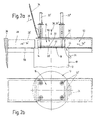
- the separating device 18 has a silo-fixed Sieve grate 20 ', while the counter surface 22 on one via the hydraulic cylinders 32 'in the direction of the double arrow 30 ', 30' 'movable and displaceable pressure plate 46 is arranged is.
- a loading frame 28 ' provided in the area of the loading section 16 laterally opposite the silo 10 from a filling station 48 to a press station 50 and from there to a separation station 52 in the direction of arrows 54 ', 54' ' is.
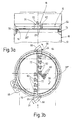
- the separator 18 has one in the direction of Arrow 58 by means of the rotary drive 60 rotating sieve grate 20 '', while the counter surfaces 22 through the scraper surfaces pointing diagonally towards the sieve grid the scraper rests against the 20 '' screen 62 are formed.
- the sieve grid 20 '' is on the silo radially via radial guide rollers 74 and axially via Axial guide rollers 76 mounted, of which several each distributed over the circumference on the silo jacket are.
- the sieve grate 20 '' is of a silage-proof jacket 64 surrounded, the two diametrically opposite, each forming a foreign body outlet 24, with a Flap 66 has closable radial openings 68.
- the remaining 20 '' on the surface of the sieve grate not through the sieve openings 69 of the sieve grate 20 '' foreign objects pass under gradually centrifugal to the outside and are caught by a foreign object 70 stopped and with the flaps 66 open in the Foreign matter outlet 24 passed.
- the invention refers to a silo for sludges, in particular for sewage sludge, with a sludge receiving part 12, with one arranged above the sludge receiving part, via an inlet opening 14 communicating with the latter Loading section 16 and with one in the lower one Area of the sludge receiving part arranged preferably connectable to a piping system Schlammaustragvorraum.
- a Separator 18 is arranged for foreign bodies.
- the foreign body separating device 18 expediently a sieve grate over the inlet opening 14 and at least one arranged above the sieve grate 20 Counter surface 22 on the press through mud through the sieve openings of the sieve grate 20 relative to one another are movable.
Landscapes
- Life Sciences & Earth Sciences (AREA)
- Hydrology & Water Resources (AREA)
- Engineering & Computer Science (AREA)
- Environmental & Geological Engineering (AREA)
- Water Supply & Treatment (AREA)
- Chemical & Material Sciences (AREA)
- Organic Chemistry (AREA)
- Filling Or Emptying Of Bunkers, Hoppers, And Tanks (AREA)
Description
- Fig. 1a und b
- die Beschickungspartie eines Silos für Klärschlämme bei geschlossenem Silodeckel und abgesenktem Siebrost in einem Vertikalschnitt und in Draufsicht;
- Fig. 1c und d
- die Beschickungspartie des Silos in Darstellungen entsprechend Fig. 1a und b bei geöffnetem Silodeckel, angehobenem Siebrost und teilweise vorgeschobenem Räumschieber;
- Fig. 2a und b
- die Beschickungspartie eines gegenüber Fig. 1 abgewandelten Ausführungsbeispiels eines Silos mit silofestem Siebrost, vertikal verschiebbarer Druckplatte und seitlich verschiebbarem Beschickungsrahmen in einer teilweise geschnittenen Seitenansicht und einer Draufsicht;
- Fig. 3a und b
- die Beschickungspartie eines weiteren abgewandelten Ausführungsbeispiels eines Klärschlamm-Silos mit rotierendem Siebrost und Abstreifern in einem Vertikalschnitt und einer Draufsicht.
Claims (17)
- Silo für Schlämme, insbesondere Klärschlämme, mit einem Schlammaufnahmeteil (12), mit einer oberhalb des Schlammaufnahmeteils (12) angeordneten über eine großflächige Einlaßöffnung (14) mit diesem kommunizierenden Beschikkungspartie (16), mit einer im unteren Bereich des Schlammaufnahmeteils (12) angeordneten, vorzugsweise an ein Rohrleitungssystem anschließbaren Schlammaustragvorrichtung und mit einer einlaßseitig angeordneten Abscheidevorrichtung (18) für Fremdkörper, dadurch gekennzeichnet, daß die Fremdkörperabscheidevorrichtung (18) in der Beschickungspartie (16) angeordnet ist.
- Silo nach Anspruch 1, dadurch gekennzeichnet, daß die Fremdkörperabscheidevorrichtung (18) einen die Einlaßöffnung (14) übergreifenden Siebrost (20,20',20") und mindestens eine oberhalb des Siebrosts angeordnete Gegenfläche (22) aufweist, die unter Durchdrücken von Schlamm durch Sieböffnungen des Siebrosts relativ zueinander bewegbar sind.
- Silo nach Anspruch 2, dadurch gekennzeichnet, daß die Fremdkörperabscheidevorrichtung (18) mindestens einen auf der dem Schlammaufnahmeteil (12) abgewandten Seite des Siebrosts (20,20',20") angeordneten Fremdkörperauslaß (24) aufweist.
- Silo nach Anspruch 2 oder 3, dadurch gekennzeichnet, daß die Fremdkörperabscheidevorrichtung (18) einen durch hochgezogene Seitenwände begrenzten, mit Schlamm beschickbaren Beschickungsrahmen (28, 28') aufweist, der so zwischen dem Siebrost (20, 20') und der Gegenfläche (22) positioniert oder positionierbar ist, daß der Siebrost und die Gegenfläche quer zur Rahmenöffnung relativ zueinander verschiebbar sind.
- Silo nach Anspruch 4, dadurch gekennzeichnet, daß die Gegenfläche (22) durch die Innenfläche eines die Beschickungspartie (16) übergreifenden Silodeckels (34) gebildet ist, und daß der Siebrost (20) mittels eines vorzugsweise hydraulischen Antriebs (32) durch den silofest angeordneten Beschickungsrahmen (28) hindurch in Richtung Silodeckel (34) verschiebbar ist.
- Silo nach Anspruch 4 oder 5, dadurch gekennzeichnet, daß die Fremdkörperabscheidevorrichtung (18) einen parallel zur Oberfläche des Siebrosts (20) in Richtung Fremdkörperauslaß verschiebbaren Räumschieber (40) aufweist.
- Silo nach einem der Ansprüche 2 bis 4, dadurch gekennzeichnet, daß der Siebrost (20') die Einlaßöffnung (14) silofest überspannt, und daß die Gegenfläche (22) an einer Druckplatte (46) angeordnet ist, die mittels eines vorzugsweise hydraulischen Antriebs (32') durch den Beschickungsrahmen (28') hindurch von oben in Richtung Siebrost (20') verschiebbar ist.
- Silo nach Anspruch 7, dadurch gekennzeichnet, daß der nach oben und unten offene Beschickungsrahmen (28') in einer neben dem Siebrost (20') befindlichen Füllstation (48) auf einer mit dem Siebrost (20') fluchtenden Unterlage (56) mit Schlamm beschickbar und von dort in Richtung Siebrost (20') verschiebbar ist.
- Silo nach Anspruch 7 oder 8, dadurch gekennzeichnet, daß der Beschickungsrahmen (28') bei angehobener Druckplatte (46) relativ zum Siebrost (20') in Richtung Fremdkörperauslaß (24) verschiebbar ist.
- Silo nach Anspruch 9, dadurch gekennzeichnet, daß der Fremdkörperauslaß (24) eine an ihrem Rand mit dem Siebrost (20') fluchtende Auslaßöffnung aufweist, über die der bodenseitig offene Beschickungsrahmen (28') hinweg verschiebbar ist.
- Silo nach einem der Ansprüche 5 bis 10, dadurch gekennzeichnet, daß der hydraulische Antrieb vier gleichzeitig betätigbare, im Eckbereich des Siebrosts (20) bzw. der Druckplatte (46) angreifende Hydrozylinder (32,32') aufweist.
- Silo nach einem der Ansprüche 1 bis 3, dadurch gekennzeichnet, daß die Gegenfläche (22) durch eine schräg in Richtung Siebrost (20'') weisende Abstreiffläche mindestens eines federnd gegen den Siebrost (20'') anliegenden Abstreifers (62) gebildet ist, und daß der Siebrost und der Abstreifer parallel zur Oberfläche des Siebrosts relativ zueinander bewegbar sind.
- Silo nach Anspruch 12, dadurch gekennzeichnet, daß der Siebrost (20'') gegenüber dem mindestens einen silofest angeordneten Abstreifer (62) verdrehbar ist.
- Silo nach Anspruch 12 oder 13, dadurch gekennzeichnet, daß mindestens ein in lichtem Abstand über dem Siebrost (20'') angeordneter, radial ausgerichteter Anschlagbalken (72) vorgesehen ist.
- Silo nach einem der Ansprüche 12 bis 14, dadurch gekennzeichnet, daß der Siebrost (20'') von einem silofesten Mantel (64) umgeben ist, der mindestens eine den Fremdkörperauslaß (24) bildende, vorzugsweise verschließbare Öffnung aufweist.
- Silo nach einem der Ansprüche 2 bis 15, dadurch gekennzeichnet, daß der Fremdkörperauslaß (24) in eine Fremdkörperkammer (26) mündet.
- Silo nach Anspruch 16, dadurch gekennzeichnet, daß die Fremdkörperkammer (26) mit Wasser zur Reinigung der Fremdkörper von Restschlamm beaufschlagbar und über eine Restschlammförderstrecke mit dem Schlammaufnahmeteil (12) verbunden ist.
Applications Claiming Priority (3)
| Application Number | Priority Date | Filing Date | Title |
|---|---|---|---|
| DE19723150 | 1997-06-03 | ||
| DE19723150A DE19723150A1 (de) | 1997-06-03 | 1997-06-03 | Silo für Schlämme |
| PCT/EP1998/002658 WO1998055410A1 (de) | 1997-06-03 | 1998-05-06 | Silo für schlämme |
Publications (2)
| Publication Number | Publication Date |
|---|---|
| EP0986520A1 EP0986520A1 (de) | 2000-03-22 |
| EP0986520B1 true EP0986520B1 (de) | 2002-08-14 |
Family
ID=7831219
Family Applications (1)
| Application Number | Title | Priority Date | Filing Date |
|---|---|---|---|
| EP98924283A Expired - Lifetime EP0986520B1 (de) | 1997-06-03 | 1998-05-06 | Silo für schlämme |
Country Status (5)
| Country | Link |
|---|---|
| US (1) | US6536601B1 (de) |
| EP (1) | EP0986520B1 (de) |
| DE (2) | DE19723150A1 (de) |
| DK (1) | DK0986520T3 (de) |
| WO (1) | WO1998055410A1 (de) |
Families Citing this family (5)
| Publication number | Priority date | Publication date | Assignee | Title |
|---|---|---|---|---|
| US7142662B2 (en) | 2000-07-11 | 2006-11-28 | Austin Logistics Incorporated | Method and system for distributing outbound telephone calls |
| JP4407544B2 (ja) * | 2005-03-11 | 2010-02-03 | セイコーエプソン株式会社 | 投射型表示装置 |
| DE102007014095A1 (de) * | 2007-03-21 | 2008-09-25 | Putzmeister Concrete Pumps Gmbh | Vorrichtung zum Auftrennen eines Schlamm-Festkörpergemenges |
| CN112455941A (zh) * | 2020-11-23 | 2021-03-09 | 西安西热锅炉环保工程有限公司 | 一种高适应性的污泥存储系统及方法 |
| CN116116078B (zh) * | 2023-04-19 | 2023-07-14 | 太原市万博建泰混凝土有限公司 | 一种混凝土污水砂石分离设备 |
Family Cites Families (9)
| Publication number | Priority date | Publication date | Assignee | Title |
|---|---|---|---|---|
| DE488319C (de) * | 1930-01-06 | Haeny & Cie E | Ansaugevorrichtung mit Saugkessel fuer Pumpen zur Foerderung von feste Bestandteile enthaltenden Fluessigkeiten | |
| FR1023506A (fr) * | 1950-08-16 | 1953-03-19 | Perfectionnements aux crépines de réservoirs et cuves | |
| JPS583733B2 (ja) * | 1978-12-25 | 1983-01-22 | 株式会社栗本鉄工所 | スラツジニ−ダ |
| JPS583732B2 (ja) * | 1978-12-25 | 1983-01-22 | 株式会社栗本鉄工所 | スラツジニ−ダ |
| US4343233A (en) * | 1980-03-31 | 1982-08-10 | Burgin Kermit H | Apparatus for producing and collecting a liquid extract and a dry by-product from a mash |
| DE3727096A1 (de) * | 1987-08-14 | 1989-02-23 | Emu Abwassertechnik Vertriebs | Umwaelzvorrichtung fuer ein schlammstapelsilo |
| DE3901100C1 (de) * | 1989-01-16 | 1990-06-13 | Santec Gmbh, 1000 Berlin, De | |
| AT394032B (de) * | 1990-09-04 | 1992-01-27 | Anton Ruef | Einrichtung zum aufbereiten von oelhaltigen schlaemmen |
| DE9115220U1 (de) * | 1991-12-07 | 1992-03-05 | Scheible Versorgungsanlagen GmbH, 7340 Geislingen | Vorrichtung zum Entsorgen von flüssigen Medien |
-
1997
- 1997-06-03 DE DE19723150A patent/DE19723150A1/de not_active Withdrawn
-
1998
- 1998-05-06 DE DE59805196T patent/DE59805196D1/de not_active Expired - Fee Related
- 1998-05-06 EP EP98924283A patent/EP0986520B1/de not_active Expired - Lifetime
- 1998-05-06 US US09/423,600 patent/US6536601B1/en not_active Expired - Fee Related
- 1998-05-06 WO PCT/EP1998/002658 patent/WO1998055410A1/de not_active Ceased
- 1998-05-06 DK DK98924283T patent/DK0986520T3/da active
Also Published As
| Publication number | Publication date |
|---|---|
| WO1998055410A1 (de) | 1998-12-10 |
| DE59805196D1 (de) | 2002-09-19 |
| DE19723150A1 (de) | 1998-12-10 |
| DK0986520T3 (da) | 2002-12-09 |
| EP0986520A1 (de) | 2000-03-22 |
| US6536601B1 (en) | 2003-03-25 |
Similar Documents
| Publication | Publication Date | Title |
|---|---|---|
| DE69735774T2 (de) | Trennvorrichtung | |
| EP0040425B1 (de) | Vorrichtung zum Entfernen von Schwemmgut und Feststoffen aus Zulaufgerinnen, insbesondere von Kläranlagen | |
| DE3010967A1 (de) | Vorrichtung zum filtrieren von feststoff/fluessigkeits-gemischen, insbesondere trueben, schlaemmen und suspensionen, oder zum reinigen von stueckigen festen materialien durch abwaschen und/oder abtrennen von stueckigen festen, insbesondere koernigen und/oder faserartigen, materialien aus feuchten materialien, insbesondere breiigen bzw. pastenfoermigen materialien durch herauswaschen, oder zum klassieren von festen koernigen und/oder stueckigen materialien nach der korngroesse und/oder absondern von festen, insbesondere verunreinigenden, bestandteilen von solchen materialien | |
| EP0525348B1 (de) | Langsandfang zum Abscheiden und Entfernen von Sand aus Zulaufgerinnen, insbesondere von Kläranlagen | |
| DE3639824A1 (de) | Filternder abscheider fuer partikel und schadgase aus rohgasen | |
| DE3881330T2 (de) | Vorrichtung zum entleeren und befuellen eines als extraktionsgefaess fuer eine durchlaufextraktionseinheit fuer pflanzenmaterial benutzbaren geschlossenen gefaesses und dasselbe verwendendes verfahren. | |
| DE2813056A1 (de) | Trennvorrichtung zum wiedergewinnen der zuschlagstoffe aus nicht-abgebundenem beton | |
| DE19600897C1 (de) | Selbstfahrende Aufbereitungsanlage zum Naßklassieren von Kies und Sand | |
| DE2402871C3 (de) | Drehtrommelfilter | |
| DE19932416A1 (de) | Vorrichtung zum Entwässern von Schlamm | |
| WO1993002800A1 (de) | Verfahren und vorrichtung zur aufbereitung von rechengut an kläranlagen | |
| DE4300709C2 (de) | Verfahren zum Entsorgen von aus einer Kraftfahrzeug-Waschstraße stammenden Abwässern und Vorrichtung zur Durchführung des Verfahrens | |
| EP0656815B1 (de) | Fördervorrichtung für beim wiederaufbereiten von restbeton anfallende zuschlagstoffe | |
| EP0986520A1 (de) | Silo für schlämme | |
| DE3715019A1 (de) | Vorrichtung zur trennung von feststoffen aus fluessigkeiten | |
| DE3736657C2 (de) | ||
| DE10200599A1 (de) | Vorrichtung zum Abscheiden von organischem und anorganischem Material aus einer Flüssigkeit | |
| WO2020030729A1 (de) | Verfahren und system zur aufbereitung von betonrestwasser | |
| DE102007014095A1 (de) | Vorrichtung zum Auftrennen eines Schlamm-Festkörpergemenges | |
| EP0672801B1 (de) | Siebelement, Entwässerungsmulde sowie Strassen- und Kanalreinigungsfahrzeug mit einem derartigen Siebelement | |
| DE19539882C2 (de) | Vorrichtung zum Waschen von verunreinigtem Rechen- oder Siebgut, insbesondere in Kläranlagen | |
| WO2021121632A1 (de) | Waschen von schüttgut | |
| DE19925151A1 (de) | Totalabscheider für Pneumatikfördereranlagen, mobile Mahl-, Quetsch- und Mischanlage und Verfahren zum Abscheiden von Fördergut und Filtern von Fördergas in Pneumatikförderer | |
| AT405278B (de) | Kombinierte vorrichtung zum abscheiden von feststoffen und fetten | |
| DE2406505C3 (de) | Drehtrommelofen zur Abfallverbrennung |
Legal Events
| Date | Code | Title | Description |
|---|---|---|---|
| PUAI | Public reference made under article 153(3) epc to a published international application that has entered the european phase |
Free format text: ORIGINAL CODE: 0009012 |
|
| 17P | Request for examination filed |
Effective date: 19991008 |
|
| AK | Designated contracting states |
Kind code of ref document: A1 Designated state(s): DE DK FR GB NL |
|
| GRAG | Despatch of communication of intention to grant |
Free format text: ORIGINAL CODE: EPIDOS AGRA |
|
| 17Q | First examination report despatched |
Effective date: 20010724 |
|
| GRAG | Despatch of communication of intention to grant |
Free format text: ORIGINAL CODE: EPIDOS AGRA |
|
| GRAG | Despatch of communication of intention to grant |
Free format text: ORIGINAL CODE: EPIDOS AGRA |
|
| GRAH | Despatch of communication of intention to grant a patent |
Free format text: ORIGINAL CODE: EPIDOS IGRA |
|
| GRAH | Despatch of communication of intention to grant a patent |
Free format text: ORIGINAL CODE: EPIDOS IGRA |
|
| GRAA | (expected) grant |
Free format text: ORIGINAL CODE: 0009210 |
|
| AK | Designated contracting states |
Kind code of ref document: B1 Designated state(s): DE DK FR GB NL |
|
| REG | Reference to a national code |
Ref country code: GB Ref legal event code: FG4D Free format text: NOT ENGLISH |
|
| REF | Corresponds to: |
Ref document number: 59805196 Country of ref document: DE Date of ref document: 20020919 |
|
| GBT | Gb: translation of ep patent filed (gb section 77(6)(a)/1977) |
Effective date: 20020902 |
|
| ET | Fr: translation filed | ||
| REG | Reference to a national code |
Ref country code: DK Ref legal event code: T3 |
|
| PLBE | No opposition filed within time limit |
Free format text: ORIGINAL CODE: 0009261 |
|
| STAA | Information on the status of an ep patent application or granted ep patent |
Free format text: STATUS: NO OPPOSITION FILED WITHIN TIME LIMIT |
|
| 26N | No opposition filed |
Effective date: 20030515 |
|
| PGFP | Annual fee paid to national office [announced via postgrant information from national office to epo] |
Ref country code: DK Payment date: 20080415 Year of fee payment: 11 Ref country code: DE Payment date: 20080523 Year of fee payment: 11 |
|
| NLT1 | Nl: modifications of names registered in virtue of documents presented to the patent office pursuant to art. 16 a, paragraph 1 |
Owner name: PUTZMEISTER CONCRETE PUMPS GMBH |
|
| PGFP | Annual fee paid to national office [announced via postgrant information from national office to epo] |
Ref country code: NL Payment date: 20080418 Year of fee payment: 11 |
|
| PGFP | Annual fee paid to national office [announced via postgrant information from national office to epo] |
Ref country code: FR Payment date: 20080414 Year of fee payment: 11 |
|
| PGFP | Annual fee paid to national office [announced via postgrant information from national office to epo] |
Ref country code: GB Payment date: 20080425 Year of fee payment: 11 |
|
| REG | Reference to a national code |
Ref country code: FR Ref legal event code: CJ Ref country code: FR Ref legal event code: CD |
|
| REG | Reference to a national code |
Ref country code: DK Ref legal event code: EBP |
|
| GBPC | Gb: european patent ceased through non-payment of renewal fee |
Effective date: 20090506 |
|
| NLV4 | Nl: lapsed or anulled due to non-payment of the annual fee |
Effective date: 20091201 |
|
| PG25 | Lapsed in a contracting state [announced via postgrant information from national office to epo] |
Ref country code: NL Free format text: LAPSE BECAUSE OF NON-PAYMENT OF DUE FEES Effective date: 20091201 |
|
| REG | Reference to a national code |
Ref country code: FR Ref legal event code: ST Effective date: 20100129 |
|
| PG25 | Lapsed in a contracting state [announced via postgrant information from national office to epo] |
Ref country code: FR Free format text: LAPSE BECAUSE OF NON-PAYMENT OF DUE FEES Effective date: 20090602 Ref country code: DK Free format text: LAPSE BECAUSE OF NON-PAYMENT OF DUE FEES Effective date: 20090531 |
|
| PG25 | Lapsed in a contracting state [announced via postgrant information from national office to epo] |
Ref country code: GB Free format text: LAPSE BECAUSE OF NON-PAYMENT OF DUE FEES Effective date: 20090506 |
|
| PG25 | Lapsed in a contracting state [announced via postgrant information from national office to epo] |
Ref country code: DE Free format text: LAPSE BECAUSE OF NON-PAYMENT OF DUE FEES Effective date: 20091201 |