EP0986688B1 - Verbesserte gelenkvorrichtung eines an einer kraftfahrzeugkarosserie schwenkbar angeordneten flügels - Google Patents
Verbesserte gelenkvorrichtung eines an einer kraftfahrzeugkarosserie schwenkbar angeordneten flügels Download PDFInfo
- Publication number
- EP0986688B1 EP0986688B1 EP98929496A EP98929496A EP0986688B1 EP 0986688 B1 EP0986688 B1 EP 0986688B1 EP 98929496 A EP98929496 A EP 98929496A EP 98929496 A EP98929496 A EP 98929496A EP 0986688 B1 EP0986688 B1 EP 0986688B1
- Authority
- EP
- European Patent Office
- Prior art keywords
- articulation
- rod
- respect
- opening member
- vehicle
- Prior art date
- Legal status (The legal status is an assumption and is not a legal conclusion. Google has not performed a legal analysis and makes no representation as to the accuracy of the status listed.)
- Expired - Lifetime
Links
- 230000000873 masking effect Effects 0.000 claims description 2
- 208000031968 Cadaver Diseases 0.000 description 4
- 238000013459 approach Methods 0.000 description 1
- 230000000295 complement effect Effects 0.000 description 1
- 230000000694 effects Effects 0.000 description 1
- 239000002184 metal Substances 0.000 description 1
- 238000000034 method Methods 0.000 description 1
Images


Classifications
-
- E—FIXED CONSTRUCTIONS
- E05—LOCKS; KEYS; WINDOW OR DOOR FITTINGS; SAFES
- E05D—HINGES OR SUSPENSION DEVICES FOR DOORS, WINDOWS OR WINGS
- E05D15/00—Suspension arrangements for wings
- E05D15/40—Suspension arrangements for wings supported on arms movable in vertical planes
-
- E—FIXED CONSTRUCTIONS
- E05—LOCKS; KEYS; WINDOW OR DOOR FITTINGS; SAFES
- E05D—HINGES OR SUSPENSION DEVICES FOR DOORS, WINDOWS OR WINGS
- E05D15/00—Suspension arrangements for wings
- E05D15/56—Suspension arrangements for wings with successive different movements
-
- E—FIXED CONSTRUCTIONS
- E05—LOCKS; KEYS; WINDOW OR DOOR FITTINGS; SAFES
- E05Y—INDEXING SCHEME ASSOCIATED WITH SUBCLASSES E05D AND E05F, RELATING TO CONSTRUCTION ELEMENTS, ELECTRIC CONTROL, POWER SUPPLY, POWER SIGNAL OR TRANSMISSION, USER INTERFACES, MOUNTING OR COUPLING, DETAILS, ACCESSORIES, AUXILIARY OPERATIONS NOT OTHERWISE PROVIDED FOR, APPLICATION THEREOF
- E05Y2201/00—Constructional elements; Accessories therefor
- E05Y2201/60—Suspension or transmission members; Accessories therefor
- E05Y2201/606—Accessories therefor
- E05Y2201/62—Synchronisation of suspension or transmission members
-
- E—FIXED CONSTRUCTIONS
- E05—LOCKS; KEYS; WINDOW OR DOOR FITTINGS; SAFES
- E05Y—INDEXING SCHEME ASSOCIATED WITH SUBCLASSES E05D AND E05F, RELATING TO CONSTRUCTION ELEMENTS, ELECTRIC CONTROL, POWER SUPPLY, POWER SIGNAL OR TRANSMISSION, USER INTERFACES, MOUNTING OR COUPLING, DETAILS, ACCESSORIES, AUXILIARY OPERATIONS NOT OTHERWISE PROVIDED FOR, APPLICATION THEREOF
- E05Y2201/00—Constructional elements; Accessories therefor
- E05Y2201/60—Suspension or transmission members; Accessories therefor
- E05Y2201/622—Suspension or transmission members elements
- E05Y2201/71—Toothed gearing
- E05Y2201/716—Pinions
-
- E—FIXED CONSTRUCTIONS
- E05—LOCKS; KEYS; WINDOW OR DOOR FITTINGS; SAFES
- E05Y—INDEXING SCHEME ASSOCIATED WITH SUBCLASSES E05D AND E05F, RELATING TO CONSTRUCTION ELEMENTS, ELECTRIC CONTROL, POWER SUPPLY, POWER SIGNAL OR TRANSMISSION, USER INTERFACES, MOUNTING OR COUPLING, DETAILS, ACCESSORIES, AUXILIARY OPERATIONS NOT OTHERWISE PROVIDED FOR, APPLICATION THEREOF
- E05Y2201/00—Constructional elements; Accessories therefor
- E05Y2201/60—Suspension or transmission members; Accessories therefor
- E05Y2201/622—Suspension or transmission members elements
- E05Y2201/71—Toothed gearing
- E05Y2201/722—Racks
-
- E—FIXED CONSTRUCTIONS
- E05—LOCKS; KEYS; WINDOW OR DOOR FITTINGS; SAFES
- E05Y—INDEXING SCHEME ASSOCIATED WITH SUBCLASSES E05D AND E05F, RELATING TO CONSTRUCTION ELEMENTS, ELECTRIC CONTROL, POWER SUPPLY, POWER SIGNAL OR TRANSMISSION, USER INTERFACES, MOUNTING OR COUPLING, DETAILS, ACCESSORIES, AUXILIARY OPERATIONS NOT OTHERWISE PROVIDED FOR, APPLICATION THEREOF
- E05Y2800/00—Details, accessories and auxiliary operations not otherwise provided for
- E05Y2800/26—Form or shape
- E05Y2800/29—Form or shape forming a unitary piece with another element
-
- E—FIXED CONSTRUCTIONS
- E05—LOCKS; KEYS; WINDOW OR DOOR FITTINGS; SAFES
- E05Y—INDEXING SCHEME ASSOCIATED WITH SUBCLASSES E05D AND E05F, RELATING TO CONSTRUCTION ELEMENTS, ELECTRIC CONTROL, POWER SUPPLY, POWER SIGNAL OR TRANSMISSION, USER INTERFACES, MOUNTING OR COUPLING, DETAILS, ACCESSORIES, AUXILIARY OPERATIONS NOT OTHERWISE PROVIDED FOR, APPLICATION THEREOF
- E05Y2900/00—Application of doors, windows, wings or fittings thereof
- E05Y2900/50—Application of doors, windows, wings or fittings thereof for vehicles
- E05Y2900/53—Type of wing
- E05Y2900/546—Tailboards, tailgates or sideboards opening upwards
Definitions
- the present invention relates to a device articulation of a motor vehicle opening, in particular a tailgate, which is pivotally mounted on the structure of the vehicle body.
- the invention relates more particularly to a device articulation in which the opening is pivotally mounted, in particular between a first extreme closed position and a second extreme position opened via a mechanism with two parallel axes of articulation connected by minus a link rod.
- Such a device is for example described and shown in document FR-A-2.717.213.
- a implementation of such a hinge device more particularly to ensure the pivoting mounting of a tailgate which, in the closed position, extends in a plane substantially vertical and which, in the open position; extends in a plane substantially horizontal above the vehicle.
- the tailgate When the rear part of a vehicle is fitted with a such tailgate, as is the case in vehicles for example of the "minivan" type, the tailgate is of dimensions and significant mass.
- This second document thus proposes, to facilitate the tailgate handling, to incorporate into the hinge device means of balancing the opening which apply a balancing torque which compensates for the resisting torque due to the opening mass.
- the user in order to be able to open or close the tailgate easily, must have a relatively large minimum space at the rear of the vehicle to allow at least the tailgate travel between its extreme closed position and its extreme position open, travel during which the panel which constitutes the tailgate moves, during the first part of the trajectory from the closed position, substantially parallel to itself and oriented substantially vertically.
- the panel goes through a substantially middle position between its two extreme positions in which it extends at a distance from the rear vertical plane of the vehicle which is substantially equal to the length of the connecting rods, this distance determining a trajectory of the lower edge of the panel, in an arc of a circle the radius increases due to the design of the articulation and movement control device which uses a rack whose longitudinal ends front and rear gears cooperate with fixed gears respectively on the structure of the opening body and on the structure of the panel.
- the object of the invention is to remedy this drawback by proposing an improved articulation device which allows you to open the tailgate even if the space available at the rear of the vehicle is very limited, especially when another vehicle is parked near the bumper back.
- the invention provides a device of the type mentioned above, characterized in what the direction of pivoting of the sash, relative to the second end of the connecting rod, reverses during pivoting movement of the first end of the connecting rod, relative to the structure of the vehicle body, between two extreme angular positions associated with the positions closed and open ends of the sash.
- FIG. 1 shows a side view of the rear part of a motor vehicle 10 whose body 12 is open at the rear to allow access to the passenger compartment 14 of the vehicle and for example its load.
- the opening is delimited by a frame which extends in a substantially vertical plane and which is essentially consisting of two vertical lateral uprights one of which is shown in Figure 1, the side upright opposite being arranged symmetrically with respect to the plane longitudinal median of general symmetry of the vehicle, and by two upper 18 and lower 20 crosspieces which delimit a recess, the closure of which is ensured by an opening 22, also called tailgate, which is generally pivotally mounted relative to the structure of the vehicle body 12, around horizontal axes.
- an opening 22 also called tailgate
- Tailgate 22 is shown in the extreme open position maximum in Figure 1.
- the opening 22 is mounted swiveling on the body 12 by a two-axis system horizontal articulation geometries A1 and A2 thanks to a articulation mechanism with two parallel connecting rods which extend substantially parallel to the longitudinal axis of the vehicle, and one of which 24 is illustrated in the figures.
- first front end 26 is hinged on the structure of the vehicle body around the first front axis A1 while the second opposite end 28 is articulated on the opening 22 around the second rear axis of articulation A2, parallel to the first axis of articulation A1, these two axes extending in the general direction transverse of the vehicle.
- the first articulation axis A1 is located vertically in the vicinity of the crosspiece 18 and, in the extreme position opening, the tailgate 22 extends in a plane substantially horizontal above the vehicle 10 and in particular partly at above his flag.
- the movement of pivoting of the opening 22 about the axis A2, relative to the second end 28 of the connecting rod 24, is generally controlled to the pivoting movement of the first end 26 of the connecting rod 24 relative to the structure 12, 16 of the body of the vehicle by a servo mechanism.
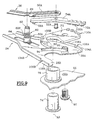
- the body of the connecting rod 24 is essential consisting of a sheet metal part cut and stamped in the general form of a plate 32 whose longitudinal and parallel edges 34A and 34B are folded at a right angle.
- the connecting rod 30 is thus in the form of a body hollow in which various components are arranged belonging to the servo mechanism.
- the servo mechanism 30 includes a rack 36 whose tubular body is slidably mounted longitudinally inside the connecting rod 24 according to a sliding general direction C, in a first direction C1 forward and in a second direction C2 backward.
- the free front end 38 of the rack 36 is a toothed sector whose teeth 40 cooperate with the teeth in opposite 42 of a first toothed pinion P1 of axis A1 fixed on a structural element of the vehicle body by through a screw 44 which carries a socket 46 for the rotational mounting, around axis A1, of the rear end 26 of the connecting rod 30.
- the toothed end 38 is maintained in cooperation with the teeth of the pinion P1 by means of a roller 45 which la spring loaded under the action of a spring 46 fixed to the connecting rod 24.
- the rear free end 28 of the rod 30 body is shaped like a fork with two parallel branches 28A and 28B which are interconnected by the shaped body of plate 32.
- the second rear end of the rack 36 is shaped like a fork with two branches articulated.
- tubular body divides into Y by two rear end branches 50A and 50B each of which its free end, around a pivot 52A, 52B, a section toothed rack 54A, 54B.
- the two toothed sections 54A, 54B thus extend longitudinally rearward, substantially parallel to the sliding direction C, from their longitudinal parts rear which are mounted articulated on the branches 50A and 50B around axes parallel to axes A1 and A2.
- Each toothed branch or section 54A, 54B extends forward beyond the pivot 52A, 52B by a tail 56A, 56B each of which carries a finger 58A, 58B which extends laterally and which cooperates with one of the branches 60A, 60B of a spring in wire 60 whose body is helically wound around a finger 62 which is slidably mounted in a rectilinear light 64 formed in the plate 32 of the body of the connecting rod 24 and which extends longitudinally in direction C, being delimited by its front end edges 66 and rear end 68.
- For sliding finger 62 with the rack 36 its other end is crimped into a hole 69 in the body of the rack.
- the toothed section 54A is resiliently stressed continuously rotating around the axis of the pivot 52A in clockwise considering Figures 3 to 5, while the opposite toothed section 54B is rotated in the counterclockwise, that is, the spring 60 tends to permanence of bringing teeth 72A, 72B closer to both sections towards each other and towards the second rear axis of articulation A2 located inside the fork.
- the second plate 70 of the body of the connecting rod 24 door in the vicinity from the rear end 28 of the latter, a pivot 74 of axis A2.
- the pivot 74 is fixed to the plate 70 and it carries in rotation, with interposition of sliding rings 76, a sleeve bearing 78 on which is rotatably mounted, about the axis A2, the body of the second toothed pinion P2 with which the sections 54A and 54B of the rack 36.
- the pinion P2 is centered by a shoulder 80 in a semicircular hole 82 of the rear part of the plate 32 of the rod body 24.
- the bearing sleeve 78 has a radial groove internal 84 in which a complementary edge 86 is received a plate 88 belonging to the tailgate 22.
- the pinion P2 is linked in rotation to the plate 88 of the tailgate 22 by means of a screw 90, eccentric with respect to the axis A2, which crosses the tab 88 and a socket 92, in which it is screwed, and which is itself carried by the pinion P2.
- the sleeve 92 is slidably mounted in a light 94 in an arc formed in the plate 32 in the vicinity of the rear end 28 of the connecting rod 24 which is delimited by two rounded ends 96 and 98.
- the pinion P2 is thus linked in rotation to the tab 88 of the tailgate 22 and the rear end 28 of the connecting rod 24 is mounted at rotation about the axis A2 relative to the leg 88 of the tailgate 22 and therefore relative to the pinion P2, the light 94 being centered on axis A2.
- the toothed pinion P2 has two toothed sectors 100A and 100B centered around the axis A2, the radius of the sector toothed 100A being greater than the radius of the toothed sector 100B.
- the teeth of the first toothed sector 100A are provided to mesh with the teeth opposite 72A of the section 54A of rack 36 while the teeth of the second sector toothed 100B are provided to mesh with the teeth 72B of the section 54B and this under the action of the spring 60.
- each of the two sections 54A, 548 comprises a finger control 102A, 102B which extend laterally opposite folded edges 34A and 34B of the end branches rear 28A and 28B of the body of the connecting rod 24.
- the folded edges 34A and 34B of the branches 28A and 28B of the rear end 28 of the connecting rod 24 constitute profiles or cams for controlling the angular positions of the sections teeth 54A and 54B which determine the engagement or engagement teeth 72A, 72B of these sections with the sectors teeth 100A and 100B of the second pinion P2.
- edge 34A of the branch 28A comprises at its free end rear an external surface 104A of clearance of section 54A, which is of centered curved profile around the axis A2 and which extends backwards, beyond a slot or notch 106A, by an internal face 108A of control of engagement or engagement of section 54A with sector 100A of pinion P2.
- edge 34B has at the end rear of branch 28B an internal engagement profile 108B the toothed section 54B which extends beyond a slot or notch 106B, towards the front by an external face 106B of clearance of section 54B.
- the rack 36 occupies its extreme rear position relative to connecting rod 24, the pivot 68 and the spring 60 being in particular located opposite the rear end 68 of the light 64.
- control finger 102A of the section 54A cooperates with the external clearance surface 104A towards which it is elastically stressed by the action of the strand 60A of the spring 60.
- control finger 102B of the section toothed 54B cooperates with the internal engagement surface 108B, i.e. the toothed section 54B cannot rotate clockwise considering figure 3, around the axis of its pivot 52B, thus ensuring the engagement teeth 72B with teeth of the toothed sector 100B of the pinion P2, the teeth being further solicited in cooperation by the action of the strand 60B of the spring 60.
- the tailgate 22 will generally pivot around the horizontal articulation axis A2 clockwise, i.e. its lower edge 23 will not describe the circular path T 'centered around axis A1, as in the case of the state of the art, but that he will instead describe the first part of the trajectory T illustrated in the figure.
- this first part trajectory during which the lower edge 23 gradually approaches the rear vertical plane of the vehicle greatly reduces the minimum distance L between the rear bumper 17 of the vehicle and the front bumper 19 of a vehicle parked behind and nearby.
- the connecting rod 24 is substantially horizontal orientation.
- the fingers 102A and 102B for controlling the sections teeth 54A and 54B are exactly opposite the slots 106A and 106B.
- the last tooth 100B 'of the toothed sector 100B of pinion P2 cooperates with the last tooth 72B 'of the toothed section 54B while the first tooth 100A 'of the toothed sector 100A cooperates with the first tooth 72A 'of the toothed section 54A.
- the control finger 102A no longer cooperates with the external clearance surface 104A and, under the action of the strand 60A of the spring 60, the toothed section 54A pivots about the axis of the pivot 52A, clockwise when considering the figures, so as to cause the meshing of the first teeth 72A 'and 100A'.
- the pivot 62 which carries the spring 60 is substantially mid-length of the light 64, i.e. the rack 36 is generally at mid-length of its maximum stroke by relative to the body of the connecting rod 24.
- the control finger 102B of the toothed section 52B of the rack 36 cooperates with the external surface of clearance 104B and, despite the action of the spring strand 60B 60, the toothed section 54B cannot pivot around the axis of its pivot 52B, counterclockwise, so it cannot accidental engagement between teeth 72B and teeth of sector 100B of pinion P2.
- control finger 102A cooperates with the internal engagement surface 108A so as to guarantee that teeth 72A always mesh with the teeth of the toothed sector 100A.
- the tailgate may well heard to be equipped with means (not shown on the figures) of known design which compensate for its mass and which facilitate its maneuvers.
Landscapes
- Engineering & Computer Science (AREA)
- Mechanical Engineering (AREA)
- Power-Operated Mechanisms For Wings (AREA)
- Body Structure For Vehicles (AREA)
- Support Devices For Sliding Doors (AREA)
Claims (8)
- Gelenksverbindungsvorrichtung für eine Tür (22), die schwenkbar an der Struktur (12) der Karosserie eines Automobils (10) montiert ist, insbesondere zwischen einer ersten, geschlossenen Endposition und einer zweiten, geöffneten Endposition, und zwar unter Zwischenschaltung eines Mechanismus mit zwei parallelen Gelenksverbindungsachsen (A1, A2), die durch zumindest eine Gelenksverbindungsstange (24) miteinander verbunden sind, deren erstes, vorderes Ende (26) drehbar um eine erste Gelenksverbindungsachse (A1) an die Struktur der Karosserie des Fahrzeugs angelenkt ist, deren zweites, hinteres Ende (28) drehbar um eine zweite Gelenksverbindungsachse (A2), die zur ersten Gelenksverbindungsachse (A1) parallel ist, an die Tür (22) angelenkt ist und die von dem Typ ist, in dem Mittel (36) zur Kopplung der Schwenkbewegung der Tür (22) in Bezug auf das zweite Ende (28) der Stange (24) an die Schwenkbewegung des ersten Endes (26) der Stange in Bezug auf die Struktur (12) der Karosserie des Fahrzeugs vorgesehen sind, dadurch gekennzeichnet, dass sich die Schwenkrichtung der Tür (22) in Bezug auf das zweite Ende der Stange im Lauf der Schwenkbewegung des ersten Endes (26) der Stange (24) in Bezug auf die Struktur der Karosserie des Fahrzeugs zwischen zwei äußersten Winkelpositionen, die mit der geschlossenen bzw. der geöffneten Endposition der Tür verbunden sind, umkehrt.
- Gelenksverbindungsvorrichtung nach dem vorhergehenden Anspruch, dadurch gekennzeichnet, dass die Kopplungsmittel einen Kopplungsmechanismus aufweisen, der insbesondere eine Zahnstange (36) umfasst, die schiebbar in Längsrichtung in Bezug auf den Körper der Stange (24) montiert ist, deren erstes gezähntes Ende (38) ständig mit einem ersten Zahnrad (P1) zusammenarbeitet, das drehbar mit der Struktur (12) der Karosserie des Fahrzeugs verbunden ist, und deren zweites Ende die Form einer Gabel aufweist, deren zwei gezähnte Zweige (54A, 54B), die annähernd parallel sind, sich nach hinten erstrecken und in der Lage sind, abwechselnd mit einem von zwei diametral entgegengesetzten gezähnten Sektoren (100A, 100B) eines zweiten Zahnrads (P2) zusammenzuarbeiten, das drehbar mit der Tür (22) verbunden ist.
- Gelenksverbindungsvorrichtung nach dem vorhergehenden Anspruch, dadurch gekennzeichnet, dass jeder der zwei Zweige (54A, 54B) der Gabel in Bezug auf den Körper (36, 50A, 50B) der Zahnstange drehbar um eine vordere Drehachse (52A, 52B) montiert ist, die parallel zu den Gelenksverbindungsachsen (A1, A2) der Stange (24) ist, und durch die Kraft einer Feder (60) zu einer Drehbewegung um seine Achse in die Richtung gezwungen wird, die dem Eingriff des Zweigs (54A, 54B) in den entsprechenden gezähnten Sektor des zweiten Zahnrads entspricht, und dass jeder Zweig Mittel (120A, 102B) zur Steuerung seiner Winkelposition umfasst, um seinen Eingriff bzw. das Lösen des Eingriffs in die Zähne des zweiten Zahnrads (P2) in Abhängigkeit von der Position in Längsrichtung des zweiten Endes der Zahnstange (36) in Bezug auf den Körper der Stange (24) hervorzurufen.
- Gelenksverbindungsvorrichtung nach dem vorhergehenden Anspruch, dadurch gekennzeichnet, dass die Steuerungsmittel einen Steuerungsdaumen (102A, 102B) umfassen, der von dem Zweig (54A, 54B) getragen wird und der sich seitlich erstreckt, um mit einer annähernd in Längsrichtung ausgerichteten Steuerungsrampe (104A, 104B, 106A, 106B, 108A, 108B) zusammenzuarbeiten, die gegenüber am Körper der Stange (32, 34A, 34B) in der Nähe des zweiten, hinteren Endes (28, 28A, 28B) dieser letztgenannten (24) gebildet ist.
- Gelenksverbindungsvorrichtung nach dem vorhergehenden Anspruch, dadurch gekennzeichnet, dass jede Rampe zwei aufeinanderfolgende Abschnitte, einen äußeren zum Lösen (104A, 104B) und einen inneren zum Eingriff (108A, 108B), umfasst, die durch einen Spalt (106A, 106B) zur Umkehrung getrennt sind, der den Übergang des Steuerungsdaumens (102A, 102B) vom einen zum anderen der zwei Abschnitte ermöglicht, die in Querrichtung in Bezug zueinander und in Bezug auf die längsgerichtete Schiebeachse der Zahnstange verschoben sind.
- Gelenksverbindungsvorrichtung nach einem der vorhergehenden Ansprüche, dadurch gekennzeichnet, dass die Tür (22) eine Heckklappe ist, die sich in geschlossener Position in einer annähernd vertikalen Ebene erstreckt und die sich in geöffneter Position in einer annähernd horizontalen Ebene über dem Fahrzeug erstreckt.
- Gelenksverbindungsvorrichtung nach Anspruch 6, dadurch gekennzeichnet, dass die Heckklappe durch ein Blech gebildet ist, das eine Aussparung eines Rahmens der Struktur verdeckt, der durch einen oberen Querträger (18), zwei seitliche Ständer (16) und einen unteren Querträger (20) begrenzt wird, wobei jeder seitliche Ständer eine Gelenksverbindungsachse (A1) des genannten Endes einer Gelenksverbindungsstange (24) der Heckklappe trägt, deren anderes Ende an eine Gelenksverbindungsachse (A2) angelenkt ist, die von der Heckklappe getragen wird.
- Gelenksverbindungsvorrichtung nach einem der vorhergehenden Ansprüche, dadurch gekennzeichnet, dass sie Mittel zur Herstellung eines Gleichgewichts der Tür umfasst, die ihr ein Gleichgewichtsmoment verleihen, das das Widerstandsmoment aufgrund der Masse der Tür ausgleicht.
Applications Claiming Priority (3)
| Application Number | Priority Date | Filing Date | Title |
|---|---|---|---|
| FR9707056A FR2764245B1 (fr) | 1997-06-06 | 1997-06-06 | Dispositif perfectionne d'articulation d'un ouvrant monte pivotant sur la caisse d'un vehicule automobile |
| FR9707056 | 1997-06-06 | ||
| PCT/FR1998/001145 WO1998055721A1 (fr) | 1997-06-06 | 1998-06-05 | Dispositif perfectionne d'articulation d'un ouvrant monte pivotant sur la caisse d'un vehicule automobile |
Publications (2)
| Publication Number | Publication Date |
|---|---|
| EP0986688A1 EP0986688A1 (de) | 2000-03-22 |
| EP0986688B1 true EP0986688B1 (de) | 2001-08-08 |
Family
ID=9507711
Family Applications (1)
| Application Number | Title | Priority Date | Filing Date |
|---|---|---|---|
| EP98929496A Expired - Lifetime EP0986688B1 (de) | 1997-06-06 | 1998-06-05 | Verbesserte gelenkvorrichtung eines an einer kraftfahrzeugkarosserie schwenkbar angeordneten flügels |
Country Status (6)
| Country | Link |
|---|---|
| US (1) | US6234563B1 (de) |
| EP (1) | EP0986688B1 (de) |
| JP (1) | JP2002504200A (de) |
| DE (1) | DE69801325T2 (de) |
| FR (1) | FR2764245B1 (de) |
| WO (1) | WO1998055721A1 (de) |
Families Citing this family (28)
| Publication number | Priority date | Publication date | Assignee | Title |
|---|---|---|---|---|
| GB2356178A (en) * | 1999-11-12 | 2001-05-16 | Ford New Holland Nv | Pivotable protective screen for an agricultural vehicle cooling system |
| US6637157B1 (en) * | 1999-12-10 | 2003-10-28 | Delphi Technologies, Inc. | Vehicle liftgate power operating system |
| US6367199B2 (en) * | 2000-02-22 | 2002-04-09 | Delphi Technologies, Inc. | Vehicle liftgate power operating system |
| US6676190B2 (en) * | 2000-04-27 | 2004-01-13 | Atoma International Corp. | Headliner mounted power liftgate drive mechanism |
| KR100364271B1 (ko) * | 2000-08-22 | 2002-12-11 | 현대자동차주식회사 | 자동차의 테일게이트 절첩장치 |
| US6755458B1 (en) * | 2000-09-29 | 2004-06-29 | Intier Automotive Closures Inc. | Liftgate force control |
| FR2816979B1 (fr) | 2000-11-20 | 2003-02-07 | Peugeot Citroen Automobiles Sa | Dispositif d'articulation d'un ouvrant de vehicule automobile, notamment d'un hayon arriere |
| US7941897B1 (en) | 2002-05-20 | 2011-05-17 | Vertical Doors, Inc. | Vertical door conversion kit |
| US6845547B2 (en) * | 2002-05-20 | 2005-01-25 | Demetrius Calvin Ham | Vertical door conversion kit |
| JP3982391B2 (ja) * | 2002-11-14 | 2007-09-26 | アイシン精機株式会社 | 駆動装置 |
| WO2005019576A1 (en) * | 2003-08-22 | 2005-03-03 | Intier Automotive Closures Inc. | Linear mechanism for closure panels |
| US6808223B1 (en) | 2004-01-14 | 2004-10-26 | Robert Baum | Two way hinge for motor vehicle doors |
| US7429070B2 (en) * | 2004-08-31 | 2008-09-30 | Frank Neubrand | Tonneau cover for a vehicle with a cargo area |
| DE202004016543U1 (de) * | 2004-10-25 | 2006-03-02 | Brose Schließsysteme GmbH & Co.KG | Antriebsanordnung zur Betätigung der Klappe eines Kraftfahrzeugs |
| JP4917968B2 (ja) * | 2007-06-01 | 2012-04-18 | 富士重工業株式会社 | 車両用リアゲート構造 |
| US7790566B2 (en) * | 2008-03-19 | 2010-09-07 | International Business Machines Corporation | Semiconductor surface treatment for epitaxial growth |
| US7631921B2 (en) * | 2008-04-30 | 2009-12-15 | Chrysler Group Llc | Closure system for a vehicle |
| FR2932124B1 (fr) * | 2008-06-05 | 2010-06-18 | Peugeot Citroen Automobiles Sa | Volet arriere de vehicule automobile et vehicule comportant un tel volet |
| JP2011235852A (ja) * | 2010-05-13 | 2011-11-24 | Honda Motor Co Ltd | リヤアンダーミラーの取付部構造 |
| FR2971738B1 (fr) * | 2011-02-17 | 2013-03-01 | Hutchinson | Systeme d'ouvrant pour un engin a moteur, en particulier pour un vehicule automobile |
| US11549295B2 (en) * | 2019-08-28 | 2023-01-10 | Gulfstream Aerospace Corporation | Cabinet and method for making the same, and aircraft including a cabinet |
| US12077038B2 (en) | 2021-12-17 | 2024-09-03 | Nissan North America, Inc. | Vehicle door assembly |
| US12005764B2 (en) | 2022-01-27 | 2024-06-11 | Nissan North America, Inc. | Rear door assembly |
| US12090825B2 (en) | 2022-01-31 | 2024-09-17 | Nissan North America, Inc. | Rear door assembly |
| US12006753B2 (en) | 2022-01-31 | 2024-06-11 | Nissan North America, Inc. | Rear door assembly |
| US11958344B2 (en) | 2022-05-06 | 2024-04-16 | Nissan North America, Inc. | Vehicle door assembly |
| US12291134B2 (en) | 2022-08-26 | 2025-05-06 | Nissan North America, Inc. | Vehicle seat assembly |
| US11987107B2 (en) | 2022-10-13 | 2024-05-21 | Nissan North America, Inc. | Rear door assembly |
Family Cites Families (7)
| Publication number | Priority date | Publication date | Assignee | Title |
|---|---|---|---|---|
| US4688844A (en) * | 1984-04-18 | 1987-08-25 | Mazda Motor Corporation | Back door structures for motor vehicles |
| FR2587656B1 (fr) * | 1985-09-23 | 1988-01-08 | Peugeot | Dispositif d'equilibrage pour volet arriere de vehicule automobile |
| FR2703005B1 (fr) | 1993-03-26 | 1995-06-09 | Renault | Dispositif d'articulation d'un hayon sur un élément de carrosserie. |
| FR2717213B1 (fr) * | 1994-03-11 | 1996-05-24 | Renault | Dispositif perfectionné d'articulation d'un ouvrant, notamment d'un hayon arrière de véhicule automobile. |
| FR2739349B1 (fr) | 1995-09-29 | 1997-11-14 | Renault | Dispositif d'articulation d'un ouvrant monte pivotant sur la caisse d'un vehicule automobile |
| US6068327A (en) * | 1997-10-21 | 2000-05-30 | Peregrine Incorporated | Upwardly folding vehicle door assembly |
| US6018912A (en) * | 1998-06-26 | 2000-02-01 | General Motors Corporation | Vehicle liftgate counter balance system |
-
1997
- 1997-06-06 FR FR9707056A patent/FR2764245B1/fr not_active Expired - Fee Related
-
1998
- 1998-06-05 WO PCT/FR1998/001145 patent/WO1998055721A1/fr not_active Ceased
- 1998-06-05 JP JP50174699A patent/JP2002504200A/ja active Pending
- 1998-06-05 EP EP98929496A patent/EP0986688B1/de not_active Expired - Lifetime
- 1998-06-05 US US09/424,853 patent/US6234563B1/en not_active Expired - Fee Related
- 1998-06-05 DE DE69801325T patent/DE69801325T2/de not_active Expired - Fee Related
Also Published As
| Publication number | Publication date |
|---|---|
| EP0986688A1 (de) | 2000-03-22 |
| WO1998055721A1 (fr) | 1998-12-10 |
| US6234563B1 (en) | 2001-05-22 |
| JP2002504200A (ja) | 2002-02-05 |
| DE69801325D1 (de) | 2001-09-13 |
| DE69801325T2 (de) | 2002-04-18 |
| FR2764245B1 (fr) | 1999-07-30 |
| FR2764245A1 (fr) | 1998-12-11 |
Similar Documents
| Publication | Publication Date | Title |
|---|---|---|
| EP0986688B1 (de) | Verbesserte gelenkvorrichtung eines an einer kraftfahrzeugkarosserie schwenkbar angeordneten flügels | |
| EP2030821B1 (de) | Öffnungselement für Kraftfahrzeug | |
| FR2706813A1 (de) | ||
| FR2752868A1 (fr) | Dispositif pour guider une porte coulissante et pivotante sur une carrosserie de vehicule | |
| FR2618390A1 (fr) | Capote pliante pour vehicule | |
| FR2636016A1 (fr) | Capote repliable pour vehicules | |
| EP1282536B1 (de) | Versenkbares starres dachsystem für cabriofahrzeug | |
| EP1272369B1 (de) | Vorrichtung eines öffnungfähigen dachs für cabrio-fahrzeug | |
| EP4556664A1 (de) | Zugangsvorrichtung für ein kraftfahrzeug mit antagonistischen türen | |
| WO1998029273A1 (fr) | Agencement pour l'acces a la partie arriere de l'habitacle d'un vehicule automobile | |
| EP1556239B1 (de) | Modulare montageeinheit für ein kfz mit faltbarem dach und ein kfz mit solch einer einheit | |
| FR2736380A1 (fr) | Mecanisme d'articulation d'un element mobile, notamment d'une portiere de vehicule automobile | |
| EP0971088B1 (de) | Gelenkvorrichtung für Motorhaube von Kraftfahrzeugen mit Haltemittel in der geschlossenen Stellung | |
| FR2739349A1 (fr) | Dispositif d'articulation d'un ouvrant monte pivotant sur la caisse d'un vehicule automobile | |
| EP1198362B1 (de) | Versenkbares dachsystem | |
| FR2793754A1 (fr) | Hayon arriere pour vehicule automobile | |
| FR2739811A1 (fr) | Vitre de custode susceptible de coulisser longitudinalement | |
| FR2890005A1 (fr) | Vehicule automobile a toit escamotable, notamment de type coupe-cabriolet. | |
| FR2824356A1 (fr) | Agencement d'une porte coulissante de vehicule automobile | |
| FR2734208A1 (fr) | Agencement d'une porte laterale sur un vehicule automobile | |
| EP1180076B1 (de) | Im kofferraum eines kraftfahrzeugs versenkbares dach | |
| FR2792027A1 (fr) | Dispositif d'articulation pour une porte louvoyante de vehicule automobile | |
| FR2854353A1 (fr) | Element arriere de toit escamotable et vehicule ainsi equipe | |
| FR2797656A1 (fr) | Agencement d'une porte coulissante sur un vehicule | |
| FR2660009A1 (fr) | Dispositif de guidage d'une porte coulissante et escamotable de vehicule, et porte coulissante equipee d'un tel dispositif. |
Legal Events
| Date | Code | Title | Description |
|---|---|---|---|
| PUAI | Public reference made under article 153(3) epc to a published international application that has entered the european phase |
Free format text: ORIGINAL CODE: 0009012 |
|
| 17P | Request for examination filed |
Effective date: 19991207 |
|
| AK | Designated contracting states |
Kind code of ref document: A1 Designated state(s): DE ES GB IT |
|
| GRAG | Despatch of communication of intention to grant |
Free format text: ORIGINAL CODE: EPIDOS AGRA |
|
| 17Q | First examination report despatched |
Effective date: 20001004 |
|
| GRAG | Despatch of communication of intention to grant |
Free format text: ORIGINAL CODE: EPIDOS AGRA |
|
| GRAH | Despatch of communication of intention to grant a patent |
Free format text: ORIGINAL CODE: EPIDOS IGRA |
|
| GRAH | Despatch of communication of intention to grant a patent |
Free format text: ORIGINAL CODE: EPIDOS IGRA |
|
| GRAA | (expected) grant |
Free format text: ORIGINAL CODE: 0009210 |
|
| AK | Designated contracting states |
Kind code of ref document: B1 Designated state(s): DE ES GB IT |
|
| PG25 | Lapsed in a contracting state [announced via postgrant information from national office to epo] |
Ref country code: IT Free format text: LAPSE BECAUSE OF FAILURE TO SUBMIT A TRANSLATION OF THE DESCRIPTION OR TO PAY THE FEE WITHIN THE PRESCRIBED TIME-LIMIT;WARNING: LAPSES OF ITALIAN PATENTS WITH EFFECTIVE DATE BEFORE 2007 MAY HAVE OCCURRED AT ANY TIME BEFORE 2007. THE CORRECT EFFECTIVE DATE MAY BE DIFFERENT FROM THE ONE RECORDED. Effective date: 20010808 Ref country code: GB Free format text: LAPSE BECAUSE OF FAILURE TO SUBMIT A TRANSLATION OF THE DESCRIPTION OR TO PAY THE FEE WITHIN THE PRESCRIBED TIME-LIMIT Effective date: 20010808 |
|
| REF | Corresponds to: |
Ref document number: 69801325 Country of ref document: DE Date of ref document: 20010913 |
|
| GBV | Gb: ep patent (uk) treated as always having been void in accordance with gb section 77(7)/1977 [no translation filed] |
Effective date: 20010808 |
|
| PG25 | Lapsed in a contracting state [announced via postgrant information from national office to epo] |
Ref country code: ES Free format text: LAPSE BECAUSE OF FAILURE TO SUBMIT A TRANSLATION OF THE DESCRIPTION OR TO PAY THE FEE WITHIN THE PRESCRIBED TIME-LIMIT Effective date: 20020228 |
|
| PLBE | No opposition filed within time limit |
Free format text: ORIGINAL CODE: 0009261 |
|
| STAA | Information on the status of an ep patent application or granted ep patent |
Free format text: STATUS: NO OPPOSITION FILED WITHIN TIME LIMIT |
|
| 26N | No opposition filed | ||
| PGFP | Annual fee paid to national office [announced via postgrant information from national office to epo] |
Ref country code: DE Payment date: 20040604 Year of fee payment: 7 |
|
| PG25 | Lapsed in a contracting state [announced via postgrant information from national office to epo] |
Ref country code: DE Free format text: LAPSE BECAUSE OF NON-PAYMENT OF DUE FEES Effective date: 20060103 |