EP0986975A1 - Cadre de support en particulier pour écran d'ordinateur - Google Patents
Cadre de support en particulier pour écran d'ordinateur Download PDFInfo
- Publication number
- EP0986975A1 EP0986975A1 EP98810929A EP98810929A EP0986975A1 EP 0986975 A1 EP0986975 A1 EP 0986975A1 EP 98810929 A EP98810929 A EP 98810929A EP 98810929 A EP98810929 A EP 98810929A EP 0986975 A1 EP0986975 A1 EP 0986975A1
- Authority
- EP
- European Patent Office
- Prior art keywords
- platform
- lever
- levers
- spindle
- support frame
- Prior art date
- Legal status (The legal status is an assumption and is not a legal conclusion. Google has not performed a legal analysis and makes no representation as to the accuracy of the status listed.)
- Withdrawn
Links
- 238000010276 construction Methods 0.000 abstract description 2
- NJPPVKZQTLUDBO-UHFFFAOYSA-N novaluron Chemical compound C1=C(Cl)C(OC(F)(F)C(OC(F)(F)F)F)=CC=C1NC(=O)NC(=O)C1=C(F)C=CC=C1F NJPPVKZQTLUDBO-UHFFFAOYSA-N 0.000 abstract 7
- 230000033001 locomotion Effects 0.000 description 6
- 238000000034 method Methods 0.000 description 2
- 230000005540 biological transmission Effects 0.000 description 1
- 238000004519 manufacturing process Methods 0.000 description 1
Images

Classifications
-
- A—HUMAN NECESSITIES
- A47—FURNITURE; DOMESTIC ARTICLES OR APPLIANCES; COFFEE MILLS; SPICE MILLS; SUCTION CLEANERS IN GENERAL
- A47B—TABLES; DESKS; OFFICE FURNITURE; CABINETS; DRAWERS; GENERAL DETAILS OF FURNITURE
- A47B21/00—Tables or desks for office equipment, e.g. typewriters, keyboards
-
- A—HUMAN NECESSITIES
- A47—FURNITURE; DOMESTIC ARTICLES OR APPLIANCES; COFFEE MILLS; SPICE MILLS; SUCTION CLEANERS IN GENERAL
- A47B—TABLES; DESKS; OFFICE FURNITURE; CABINETS; DRAWERS; GENERAL DETAILS OF FURNITURE
- A47B2200/00—General construction of tables or desks
- A47B2200/0035—Tables or desks with features relating to adjustability or folding
- A47B2200/005—Leg adjustment
- A47B2200/0065—Bellows for desk legs
Definitions
- the invention relates to a support frame, in particular for a Screen device according to the preamble of claim 1.
- a support frame in particular for a Screen device according to the preamble of claim 1.
- DE-A-41 27 827 is a genus comparable Carrier became known, the vertical section in essentially has a Z-shape.
- the upper arm of the Z forms doing the platform and the lower arm the base while the angle of the diagonal part between the Z arms over one electric servomotor is changeable.
- One disadvantage of this Construction is that the platform is not complete can be lowered onto the base and when changing cover a relatively large swivel radius got to.
- the height adjustment of the The platform should be as space-saving as possible can, being in the completely lowered state the level of Platform only slightly above the level of the support surface of the base.
- the scissor lever gear with the at least two scissors-like crossing and articulated Levering is ideal for a practically vertical Platform lifting motion.
- the gearbox can only be used a push spindle, which is also articulated is stored, and which to adjust the lever position one of the levers attacks.
- the levers can be special advantageously be spreadable into a basic position in which on a common level approximately parallel to the level of Base.
- the support level is in this position of the base and the support level of the platform only slightly plane-parallel one above the other.
- the frame can therefore be special advantageously placed on an existing table surface, with a screen placed on it only a few Centimeters above the table surface.
- Another advantage this lever geometry is that even with a Inclined position of the platform in the extended state, i.e. with a lever shortened on one side, the platform in tilts back to a horizontal level because all pivot points of the lever scissors on a common plane lie.
- the thrust spindle is advantageously articulated on the base and runs in the basic position also in the level of Lever. As a result, the thrust spindle is in the basic position not disturbing in appearance. To open the scissors however, a dead center can be overcome and in the initial phase the lever erection are due to the extremely short Large forces required. This can help that to reduce the leverage when extending the push spindle is arranged at least one ramp, on which the thrust spindle runs and on which it can be raised the lever is raised. The ramp works evidently as a wedge that supports the lifting movement.
- a guide element can also be arranged on the push spindle be that engages in a guide link on the lever. Depending on the training, the management team can also do this serve the dead center for raising the lever in the basic position to overcome.
- the leadership backdrop guarantees but also a calm and uniform movement when standing up the scissors and they can make a stop for the maximum Form the topping-up position. Also as a return aid for Lowering the platform plays the role of leadership.
- a certain inclination of the platform is desired.
- This can be achieved particularly simply in that at least one of the levers the distance between the pivot points of the Lever linkage is adjustable.
- the adjustable lever can have two telescopically slidable profiles, a set screw being arranged on a profile which engages in an adjusting nut on the other profile. Because the inclination of the platform is rarely changed manual adjustability is sufficient.
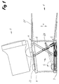
- Figure 1 shows an overall view of a support frame 1, which is essentially a base 3 and a platform 4th having.
- Articulated gear 5 is the platform 4 in the direction of the arrow a adjustable height.
- a threaded spindle 11 can the platform 4 between a basic position G and one Extend position A can be moved to any position.
- the platform 4 is also provided with an additional pad 21 on which, for example a keyboard can be stored.
- the entire articulated gear is surrounded by a bellows 28, so that the support frame from the outside one on the side lying accordion.
- the thrust spindle 11 engages to raise the scissor lever each on the first lever 7 of each pair of levers 6.
- the thrust spindle 11 is articulated on a joint 25 on the base 3.
- Electric motor 22 for actuating the push spindle is immediate flanged on the side. This electric motor can over a mobile switch 29 are operated. In particular In cases, however, it would also be conceivable to use the push spindle manually driven by a crank.
- a yoke-like Thrust element 20 arranged, on the outside of each one Pair of rollers, consisting of a ramp roller 13 and one Guide roller 15 is arranged.
- the guide roller 15 is compared to the ramp roller 13 approximately twice as wide, so that they are also outside the movement plane of the Ramp role is effective.
- a ramp 12 is arranged on the base 3, which extends approximately over the entire height of the base.
- the Guide rollers 15 act with a hook-like curved one Leading gate 14 together, which on the inside on the first Lever 7 is arranged. Every management backdrop has approximately parallel guide sections, which are approximately at a distance from the Diameter of a single guide roller arranged from each other are.
- the guide scenes are so slanted on first lever 7 arranged that the one you defined Slideway at an angle to the longitudinal direction of the first lever 7 runs.
- the first lever 7 of each pair of levers 6, 6 ' consists of each a fixed profile 16 and a pull-out profile 17.
- the two Profiles can be telescoped.
- On one Carriage 30 is the pull-out profile 17 in the direction of the arrow b movable.
- the slides of the two pairs of levers 6, 6 ' are firmly connected to one another via a connecting yoke 26.
- the two fixed profiles 16 are also connected to each other via a screw plate 31.
- By Turning the adjusting screw 18 can obviously be the first Lever 7 extended or shortened compared to the second lever 8 with which an inclination of the platform 4 can be achieved.
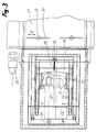
- the platform 4 is a hollow body that is open on the underside educated.
- the electric motor 22 Since the electric motor 22 has a height that is larger than that of the base 3, is on the platform 4 Housing section 23 arranged, the one open at the bottom Cavity forms and the part that projects beyond the base 3 of the electric motor 22 picks up. At the same time, this serves Housing section 23 but also as a rear stop for a screen device 2 ( Figure 1).
- an additional pad 21 attached at the front end of the platform 4 .
- This is along guide slots 32 adjustable in the direction of the arrow d and can be attached to knurled screws 33 can be fixed. This allows the optimal working position selected for keyboard and mouse button relative to the screen become.
- the additional pad is also pivotable hinged to the platform 4 so that it is about a joint 34 ( Figure 2) is pivotable in the direction of arrow e. Is with Lowering the platform an object under the additional support, this does not cause the whole frame to tilt, but only to swing the additional support up.
- the extended position A is reached as soon as the push spindle 11 has reached its end position.
- the push spindle 11 is retracted, the whole process is reversed.
- the shape of the leadership backdrop 14 causes the return of the scissor lever, the Lowering process is usually carried out by the platform 4 weight is supported.
Landscapes
- Refuge Islands, Traffic Blockers, Or Guard Fence (AREA)
Priority Applications (1)
| Application Number | Priority Date | Filing Date | Title |
|---|---|---|---|
| EP98810929A EP0986975A1 (fr) | 1998-09-17 | 1998-09-17 | Cadre de support en particulier pour écran d'ordinateur |
Applications Claiming Priority (1)
| Application Number | Priority Date | Filing Date | Title |
|---|---|---|---|
| EP98810929A EP0986975A1 (fr) | 1998-09-17 | 1998-09-17 | Cadre de support en particulier pour écran d'ordinateur |
Publications (1)
| Publication Number | Publication Date |
|---|---|
| EP0986975A1 true EP0986975A1 (fr) | 2000-03-22 |
Family
ID=8236328
Family Applications (1)
| Application Number | Title | Priority Date | Filing Date |
|---|---|---|---|
| EP98810929A Withdrawn EP0986975A1 (fr) | 1998-09-17 | 1998-09-17 | Cadre de support en particulier pour écran d'ordinateur |
Country Status (1)
| Country | Link |
|---|---|
| EP (1) | EP0986975A1 (fr) |
Cited By (3)
| Publication number | Priority date | Publication date | Assignee | Title |
|---|---|---|---|---|
| GB2370171A (en) * | 2000-10-10 | 2002-06-19 | Ned Kandeh Sesay | Monitor mount with motor-driven adjustment |
| CN100395687C (zh) * | 2005-11-28 | 2008-06-18 | 华硕电脑股份有限公司 | 高度调整装置 |
| DE202009014369U1 (de) * | 2009-10-23 | 2011-03-03 | Braun, Wolfgang | Bildschirmgehäuse sowie Vorrichtung zur Abdeckung eines Zwischenraumes zwischen einer Wand und einem an der Wand befestigten Bildschirmgehäuse |
Citations (4)
| Publication number | Priority date | Publication date | Assignee | Title |
|---|---|---|---|---|
| US4365561A (en) * | 1978-10-12 | 1982-12-28 | Compagnie Du Roneo | Computer terminal station for data input and output |
| US4934647A (en) * | 1989-08-09 | 1990-06-19 | Northrop Corporation | Universal mount |
| DE4127827A1 (de) | 1991-08-22 | 1993-02-25 | Ivan Mallinowski | Gestell |
| FR2744892A1 (fr) * | 1996-02-15 | 1997-08-22 | Joseph Pierre Gilbert | Bureau de luxe integrant un systeme d'extraction d'ordinateur |
-
1998
- 1998-09-17 EP EP98810929A patent/EP0986975A1/fr not_active Withdrawn
Patent Citations (4)
| Publication number | Priority date | Publication date | Assignee | Title |
|---|---|---|---|---|
| US4365561A (en) * | 1978-10-12 | 1982-12-28 | Compagnie Du Roneo | Computer terminal station for data input and output |
| US4934647A (en) * | 1989-08-09 | 1990-06-19 | Northrop Corporation | Universal mount |
| DE4127827A1 (de) | 1991-08-22 | 1993-02-25 | Ivan Mallinowski | Gestell |
| FR2744892A1 (fr) * | 1996-02-15 | 1997-08-22 | Joseph Pierre Gilbert | Bureau de luxe integrant un systeme d'extraction d'ordinateur |
Cited By (3)
| Publication number | Priority date | Publication date | Assignee | Title |
|---|---|---|---|---|
| GB2370171A (en) * | 2000-10-10 | 2002-06-19 | Ned Kandeh Sesay | Monitor mount with motor-driven adjustment |
| CN100395687C (zh) * | 2005-11-28 | 2008-06-18 | 华硕电脑股份有限公司 | 高度调整装置 |
| DE202009014369U1 (de) * | 2009-10-23 | 2011-03-03 | Braun, Wolfgang | Bildschirmgehäuse sowie Vorrichtung zur Abdeckung eines Zwischenraumes zwischen einer Wand und einem an der Wand befestigten Bildschirmgehäuse |
Similar Documents
| Publication | Publication Date | Title |
|---|---|---|
| EP0482333B1 (fr) | Table avec une surface de travail mobile | |
| DE2741989A1 (de) | Moebeleinheit als bett/schreibtisch- kombination | |
| DE2618943A1 (de) | Lehnstuhl mit motorisch betriebener kipplehnen- und sitzhebemechanik | |
| DE102017009249B4 (de) | Kleinfertiger sowie Verfahren zum Betrieb eines Kleinfertigers | |
| WO2016050941A1 (fr) | Table réglable en hauteur | |
| DE19543301A1 (de) | Hubvorrichtung für Sitz-, Liege- oder Abstellflächen | |
| EP2086488A1 (fr) | Lit de soins avec une partie de tête réglable | |
| EP0513838A1 (fr) | Table multifonction | |
| EP0364822B1 (fr) | Table avec cadre et surface de travail ainsi que dispositif de positionnement pour varier la hauteur et l'inclinaison de la surface de travail | |
| DE102004053941B3 (de) | Ausziehtisch | |
| DE19604074B4 (de) | Hubvorrichtung für Pflegebetten | |
| EP0642780B1 (fr) | Lit d'accouchement | |
| DE3933237C2 (fr) | ||
| EP1362823B1 (fr) | Elévateur pour véhicules, à bras porteurs | |
| EP0804887B1 (fr) | Superstructure pour tables de travail | |
| AT17997U2 (de) | Schreibtisch | |
| EP0278291B1 (fr) | Table de travail | |
| DE202004008622U1 (de) | Beschlag für ein ausfahrbares Möbelelement, insbesondere für eine Fußstütze oder eine Liegeflächenverbreiterung eines Sitz- oder Liegemöbels | |
| DE69501649T2 (de) | Fusstütze für einen stuhl oder einen lehnstuhl | |
| DE9116020U1 (de) | Fluggasttreppe | |
| EP0927529A1 (fr) | Table avec élément de plateau réglable en hauteur | |
| DE202006006004U1 (de) | Bettrahmen | |
| AT527257A1 (de) | Schreibtisch | |
| DE9104892U1 (de) | Kranken- oder Pflegebett | |
| EP1813170B1 (fr) | Meuble destiné à s'asseoir ou à s'allonger |
Legal Events
| Date | Code | Title | Description |
|---|---|---|---|
| PUAI | Public reference made under article 153(3) epc to a published international application that has entered the european phase |
Free format text: ORIGINAL CODE: 0009012 |
|
| AK | Designated contracting states |
Kind code of ref document: A1 Designated state(s): AT BE CH CY DE DK ES FI FR GB GR IE IT LI LU MC NL PT SE |
|
| AX | Request for extension of the european patent |
Free format text: AL;LT;LV;MK;RO;SI |
|
| AKX | Designation fees paid | ||
| STAA | Information on the status of an ep patent application or granted ep patent |
Free format text: STATUS: THE APPLICATION IS DEEMED TO BE WITHDRAWN |
|
| 18D | Application deemed to be withdrawn |
Effective date: 20000923 |
|
| REG | Reference to a national code |
Ref country code: DE Ref legal event code: 8566 |