EP0804887B1 - Superstructure pour tables de travail - Google Patents
Superstructure pour tables de travail Download PDFInfo
- Publication number
- EP0804887B1 EP0804887B1 EP97107243A EP97107243A EP0804887B1 EP 0804887 B1 EP0804887 B1 EP 0804887B1 EP 97107243 A EP97107243 A EP 97107243A EP 97107243 A EP97107243 A EP 97107243A EP 0804887 B1 EP0804887 B1 EP 0804887B1
- Authority
- EP
- European Patent Office
- Prior art keywords
- pull
- attachment according
- desk
- storage shelf
- elements
- Prior art date
- Legal status (The legal status is an assumption and is not a legal conclusion. Google has not performed a legal analysis and makes no representation as to the accuracy of the status listed.)
- Expired - Lifetime
Links
Images
Classifications
-
- A—HUMAN NECESSITIES
- A47—FURNITURE; DOMESTIC ARTICLES OR APPLIANCES; COFFEE MILLS; SPICE MILLS; SUCTION CLEANERS IN GENERAL
- A47B—TABLES; DESKS; OFFICE FURNITURE; CABINETS; DRAWERS; GENERAL DETAILS OF FURNITURE
- A47B17/00—Writing-tables
- A47B17/03—Writing-tables with substantially horizontally extensible or adjustable parts other than drawers, e.g. leaves
- A47B17/033—Writing-tables with substantially horizontally extensible or adjustable parts other than drawers, e.g. leaves with parts added to the original furniture to enlarge its surface
-
- A—HUMAN NECESSITIES
- A47—FURNITURE; DOMESTIC ARTICLES OR APPLIANCES; COFFEE MILLS; SPICE MILLS; SUCTION CLEANERS IN GENERAL
- A47B—TABLES; DESKS; OFFICE FURNITURE; CABINETS; DRAWERS; GENERAL DETAILS OF FURNITURE
- A47B19/00—Reading-desks; Lecterns; Pulpits, i.e. free-standing
-
- A—HUMAN NECESSITIES
- A47—FURNITURE; DOMESTIC ARTICLES OR APPLIANCES; COFFEE MILLS; SPICE MILLS; SUCTION CLEANERS IN GENERAL
- A47B—TABLES; DESKS; OFFICE FURNITURE; CABINETS; DRAWERS; GENERAL DETAILS OF FURNITURE
- A47B21/00—Tables or desks for office equipment, e.g. typewriters, keyboards
- A47B21/03—Tables or desks for office equipment, e.g. typewriters, keyboards with substantially horizontally extensible or adjustable parts other than drawers, e.g. leaves
-
- A—HUMAN NECESSITIES
- A47—FURNITURE; DOMESTIC ARTICLES OR APPLIANCES; COFFEE MILLS; SPICE MILLS; SUCTION CLEANERS IN GENERAL
- A47B—TABLES; DESKS; OFFICE FURNITURE; CABINETS; DRAWERS; GENERAL DETAILS OF FURNITURE
- A47B37/00—Tables adapted for other particular purposes
- A47B2037/005—Tables specially adapted for laboratories
Definitions
- the invention relates to a table attachment for work tables, with a shelf and spacers to position the shelf above the user opposite rear area of the worktop of the Worktable, with the shelf in relation to the Worktop has a shallower depth.
- Such table tops are known for example from DE-A-4 112 180, for computer work tables also from EP-A-0 523 310, in particular to monitor in position at a certain height.
- the well-known Table tops are usually fixed in height mounted on the worktop or on the worktable.
- This object is achieved in that optional formation of a standing desk-like table arrangement the table attachment with means for reversible enlargement the depth of the shelf to the front front worktop area.
- the table attachment With the table attachment according to the invention, existing ones can also be Work tables are retrofitted so that a Standing desk with relatively little conversion work and financial Effort can be realized even if space is tight Space is available.
- the Table attachment from the start, even with new tables be provided.
- a work table gets a double function: in the enlarged Condition the table attachment changes the work table into a standing desk, and in the not enlarged It forms the condition when the work table is used normally an additional one when the user is sitting increased second storage space. This remains in the enlarged Condition preserved, so that for example an on monitor located on the shelf the enlargement to the standing desk can maintain.
- the table top can also completely again at least temporarily from Worktop can be removed if, for example, its entire area is needed to spread large Drawings or the like
- the Storage plate plate or strip-like fold-out elements arranged, preferably with each other and with the Storage plate are connected via joints or hinges.
- the storage plate can also have at least one a plate-like or strip-like pull-out element be provided, the storage plate preferably a Cavity for receiving the at least one pull-out element has, or this at least one pull-out element is in the inserted state below the shelf arranged.
- a cavity for receiving the at least one pull-out element has, or this at least one pull-out element is in the inserted state below the shelf arranged.
- Extendable pull-out elements provided in a scale-like manner his.
- Wise means of stiffening the unfolded Fold-out elements or extended pull-out elements provided an entire plate.
- These funds can in particular as telescopically extendable guide tubes or be designed as pivotable articulated arms, or the fold-out elements or pull-out elements are one below the other connected with lanyards together with the pull-out or pull-out elements are self-supporting Form a plate.
- a particularly favorable structural design exists in that the swing-out articulated arms on the rear Holding feet for the shelf can be swiveled horizontally arranged and with their free end areas at the forefront Pull-out element are attached or coupled.
- the articulated arms swung out at the same time, and that foremost pull-out element and the following pull-out elements lie securely and firmly on the articulated arms.
- At least one other pull-out element is included coupled to the foremost pull-out element so that it is pulled out this foremost pull-out element after this is pulled out.
- the pull-out elements are in the extended state Sloping faces together, which is a double advantage offers.
- there is a pushing force when inserted transferred so that through the first also the following Pull-out elements are pushed in, and to others allow these inclined surfaces each time they are reached a rear stop through one of the pull-out elements pushing this and the next one under the other Pull-out element.
- the spacing devices are expediently as Holding feet formed, at least part of the Holding feet with fixing devices for fixing to the Worktop is provided.
- the pull-out or pull-out elements with sliding Holding feet provided, so that only the latter Holding feet to increase the depth towards the user moved or subsequently pushed away again have to.
- the holding feet advantageously at least partially height adjustable. It is also conditional possible, for example, to implement an inclined surface.
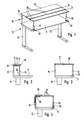
- FIGS. 1 and 2 there is a work table 10, for example a usual desk or computer desk, from one Countertop 11, the side areas of two on the narrow arranged feet 12 is worn.
- a work table 10 for example a usual desk or computer desk, from one Countertop 11, the side areas of two on the narrow arranged feet 12 is worn.
- the illustrated work table 10 can of course other usual work tables, for example also work tables with four feet.
- a Table attachment 13 On the worktop 11 of the worktable 10 is a Table attachment 13 arranged. This essentially exists from a storage plate 14, which is spaced by means of holding feet 15 and essentially parallel to the countertop 11 is arranged above this. This storage plate 14 has a length that is essentially that of the worktop 11 corresponds, but a much smaller one Depth, and is above that of the user of the worktable 10 opposite rear area of the worktop 11 positioned.
- the holding feet 15 are not shown in FIG Fixed on the worktop 11, for example with retaining screws, retaining brackets, screw terminals or the like.
- the two fold-out elements When folded out, the two fold-out elements form 16, 17 together with the storage plate 14 a flat plate, the size of which is essentially that of the worktop 11 corresponds.
- the hinges 18 are designed so that the fold-out elements 16, 17 together with the Storage plate 14 form a self-holding plate. 2 in the folded state of the work table 10 has its usual function and the table attachment 13 only by the storage plate 14 an additional Storage space in a higher level creates, transforms the table top 13 in its unfolded state the work table 10 to a standing desk according to FIG. 1, to work either sitting or standing to be able to execute. Should be back to the seated Activity to be returned, it is only necessary by folding in the fold-out elements 16, 17 and pushing back the holding feet 19 shown in Fig. 2 Restore condition. On the shelf 14 items can be parked in and out State there.
- Both the holding feet 15 and the holding feet 19 are height adjustable to the height of the table attachment 13 to the to be able to adapt desired requirements. It is also possible to set different heights, for example to realize an inclined surface.
- hinges 18 can also simpler hinges are used, and the level Area of the fold-out elements 16, 17 and the storage plate 14 is formed by plate Telescopic extendable guide tubes, not shown formed on which the fold-out elements 16, 17 rest.
- Such telescopically extendable guide tubes are e.g. known in connection with extending tables, whereby other extendable table fittings can also be used here.
- FIG. 3 has one compared to the first embodiment modified shelf 21 a cavity Inclusion of a plate or strip-like pull-out element 22.
- the extended state is shown in FIG. 3, in which the pull-out element 22 together with the Storage plate 21 form an enlarged area which in essential of the worktop 11 of the worktable 10 corresponds.
- the pull-out element is pushed in 22 is again the usual function of the work table 10 manufactured, and the one opposite the Worktop 11 having a much smaller depth Storage plate 21 serves only as an additional Storage area on an elevated level.
- the sliding Retaining feet 19 are on the free corner areas the pull-out element 22 fixed.
- pull-out element 22 can of course here also several pull-out elements 22 occur, which can be telescoped or pulled apart are trained. In another variation can also overlap several pull-out elements in a scale-like manner above or below the shelf 21 or the storage plate 14 arranged and designed extractable his. Even with such a version, it is possible at least to stabilize the plate surface formed a telescopically extendable guide tube.
- FIG. 4 In the third embodiment shown in FIG. 4 is a variety of slat-like pull-out elements 23 in the manner of a roller shutter curtain lined up.
- Rear support feet 24, on which a shelf 25 is fixed, have a in the upper area Curvature 26, along which the shuttered armor rows Pull-out elements 23 behind these holding feet 24 can slide down so that this curvature 26 as Guide curvature is formed.
- Fig. 4 represents the extracted state represents, i.e. the state in which the work table 10 as Standing desk can be used.
- the front support feet 19 are lined up at the front free end area of the Pull-out elements 23 fixed.
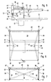
- FIGS. 5 to 7 are two vertical feet 30 am rear edge of the worktop 11 by means of conventional clamping devices 31 fixed.
- On each of the holding feet 30 an articulated arm 32 pivotally mounted, in which the Extend holding feet 30 through corresponding bearing tubes 33, on which the articulated arms 32 are rigidly fixed.
- This Bearing tubes 33 are adjustable in height on the holding feet 30 arranged bearing rings 34.
- the bearing rings 34 and thus the articulated arms 32 serve plug-in elements 35, horizontally through the bearing rings 34 and by arranged in different height positions Cross bores 36 are variably pluggable.
- the bearing rings 34 also other known Have height adjustment devices.
- each of these holding tubes 37 holding wall 38 made of sheet metal, for example fixed, the two retaining walls 38 parallel to each other are aligned and a shelf between them 39 hold, thus in the desired amount of behind the worktop 11.
- the holding tubes 37 are above the shelf 39 by a stabilizing Crossbar 40 connected together.
- the retaining walls 38 serve in addition to fixing the shelf 39 also as a side retaining wall for on the shelf 39 items placed.
- The serves accordingly Cross bar 40 as a rear stop and rear support for such items.
- the slots 46 are so far above the support plane arranged on the articulated arms 32 so that the front pull-out member 44 under the rear pull-out member 43 can be pushed.
- At the two front corner areas of the front pull-out element 44 are holding bolts or holding screws 48 which are articulated in the engage front free end regions of the articulated arms 32.
- the articulated arms 32 have a swivel joint approximately in the middle 49, the length of the articulated arms 32 being dimensioned that in the fully extended state according to FIGS. 5 and 6 the articulated arms 32 are still not stretched, but still are slightly buckled to ensure high stability Arrangement and problem-free insertion of the pull-out elements to ensure.
- Coupling devices between the pull-out elements 43, 44 occur when pulling out a non-positive Connection and when pushing one over the other guarantee, e.g. Locking devices.
- the width of the entire table top 13 can be less than the width of the Worktop 11, for example laterally another Screen or the like to set up.
- Wise stackable or non-stackable trays for holding of forms or other things for example, can be fixed to the crossbar 40.
Landscapes
- Tables And Desks Characterized By Structural Shape (AREA)
- Workshop Equipment, Work Benches, Supports, Or Storage Means (AREA)
- Forklifts And Lifting Vehicles (AREA)
Claims (15)
- Superstructure pour tables de travail, comprenant un plan et des dispositifs d'espacement destinés à assurer le positionnement du plan au-dessus de la zone arrière, opposée à l'utilisateur, du plan de travail de la table de travail, le plan présentant une profondeur inférieure à celle du plan de travail, caractérisée en ce qu'afin de former, si on le souhaite, un dispositif formant table du type pupitre, la superstructure (13) est équipée de moyens permettant d'augmenter, de façon réversible, la profondeur du plan (14 ; 21 ; 25 ; 39), en direction de l'avant, jusque dans la zone antérieure du plan de travail.
- Superstructure selon la revendication 1, caractérisée en ce que sont montés, sur le plan (14), des éléments escamotables (16, 17) du type plaques ou lattes qui sont, de préférence, reliés entre eux et avec le plan (14), par des articulations ou des charnières (18).
- Superstructure selon la revendication 1, caractérisée en ce que le plan (21 ; 39) est équipé de plusieurs éléments télescopiques (23), du type lamelles, susceptibles d'être tirés, disposés les uns à côté des autres à la façon d'un blindage de volet roulant, ou d'au moins un élément télescopique (22 ; 43, 44), du type plaque ou latte qui, à l'état rentré, vient se placer de préférence sous le plan (39).
- Superstructure selon la revendication 3, caractérisée en ce que le plan (21) comprend un espace creux destiné à recevoir un élément télescopique (22), au nombre minimum d'un.
- Superstructure selon la revendication 3 ou 4, caractérisée en ce que sont prévus plusieurs éléments télescopiques (43, 44) qui peuvent être déployés à la façon d'éléments imbriqués.
- Superstructure selon l'une des revendications 2 à 5, caractérisée en ce que sont prévus des moyens pour rigidifier les éléments escamotables dépliés ou les éléments télescopiques déployés pour former une plaque entière.
- Superstructure selon la revendication 6, caractérisée en ce que les moyens sont conformés en tubes de guidage pouvant être déployés de façon télescopique ou en bras articulés pouvant être dégagés par pivotement.
- Superstructure selon la revendication 7, caractérisée en ce que les bras articulés (32) pouvant être dégagés par pivotement sont montés horizontalement pivotants sur des pieds de maintien (30) postérieurs, destinés au plan (39), et sont fixés ou couplés, par leurs zones terminales libres, à l'élément télescopique situé le plus en avant.
- Superstructure selon la revendication 8, caractérisée en ce qu'au moins un élément télescopique (43) supplémentaire est couplé à l'élément télescopique (44) antérieur de telle sorte que lorsque cet élément télescopique antérieur (44) est tiré, cet élément télescopique antérieur (44) est également déployé et vient lui faire suite.
- Superstructure selon la revendication 9, caractérisée en ce que les éléments télescopiques (43, 44), lorsqu'ils sont tirés, sont disposés les uns contre les autres, avec interposition de surfaces inclinées qui, lorsque les éléments sont rétractés, transmettent une poussée et qui permettent, lorsque l'un des éléments télescopiques (43) atteint une butée postérieure, que celui-ci et l'élément télescopique (44) suivant viennent se placer l'un sous l'autre.
- Superstructure selon la revendication 6, caractérisée en ce que les éléments escamotables (16, 27) ou télescopiques (22, 23) sont reliés entre eux par des moyens de liaison qui constituent, avec les éléments escamotables ou télescopiques, une plaque autoporteuse.
- Superstructure selon l'une des revendications 3 à 11, caractérisée en ce que les éléments télescopiques (22 ; 23 ; 43, 44) sont conformés en éléments pouvant être déployés sans à-coups.
- Superstructure selon l'une des revendications précédentes, caractérisée en ce que les dispositifs d'espacement conformés en pieds de maintien (15 ; 24 ; 30) sont équipés, au moins partiellement, de dispositifs de fixation (31) destinés à être fixés sur le plan de travail (11), et/ou en ce que les pieds de maintien (15 ; 19 ; 24 ; 30 ; 41), au moins partiellement, sont réglables en hauteur et/ou susceptibles d'être repliés vers l'intérieur.
- Superstructure selon la revendication 13, caractérisée en ce que le plan (14, 21, 25) est équipé de pieds de maintien (15, 24) susceptibles d'être fixés sur le plan de travail (11) et la zone terminale libre des éléments escamotables ou télescopiques (16, 17, 22, 23) est pourvue de pieds de maintien (19) déplaçables.
- Superstructure selon la revendication 13, caractérisée en ce que le plan (39) est pourvu de pieds de maintien (30) susceptibles d'être fixés sur le plan de travail (11) et, de préférence, de pieds de maintien (41) supplémentaires, s'appuyant sur le plan de travail (11).
Applications Claiming Priority (2)
| Application Number | Priority Date | Filing Date | Title |
|---|---|---|---|
| DE19617536 | 1996-05-02 | ||
| DE19617536A DE19617536A1 (de) | 1996-05-02 | 1996-05-02 | Tischaufsatz für Arbeitstische |
Publications (2)
| Publication Number | Publication Date |
|---|---|
| EP0804887A1 EP0804887A1 (fr) | 1997-11-05 |
| EP0804887B1 true EP0804887B1 (fr) | 2000-09-13 |
Family
ID=7793062
Family Applications (1)
| Application Number | Title | Priority Date | Filing Date |
|---|---|---|---|
| EP97107243A Expired - Lifetime EP0804887B1 (fr) | 1996-05-02 | 1997-05-01 | Superstructure pour tables de travail |
Country Status (3)
| Country | Link |
|---|---|
| EP (1) | EP0804887B1 (fr) |
| AT (1) | ATE196226T1 (fr) |
| DE (2) | DE19617536A1 (fr) |
Families Citing this family (6)
| Publication number | Priority date | Publication date | Assignee | Title |
|---|---|---|---|---|
| DE19857736C2 (de) * | 1998-10-21 | 2002-12-05 | Haworth Bueroeinrichtung Gmbh | Abschirmeinrichtung für eine Tischanordnung |
| CN101803826B (zh) * | 2010-04-12 | 2012-07-25 | 王鸣阳 | 可折叠的桌子 |
| WO2013176690A1 (fr) | 2012-05-24 | 2013-11-28 | Gemmy Industries Corporation | Plateforme de bureau réglable |
| KR102093582B1 (ko) * | 2019-09-10 | 2020-03-25 | 김승민 | 공간활용성이 향상된 선반 내장형 컴퓨터 책상 |
| USD1023624S1 (en) | 2021-08-16 | 2024-04-23 | AMQ Solutions, LLC | Collapsible workstation |
| USD1023627S1 (en) | 2021-08-16 | 2024-04-23 | AMQ Solutions, LLC | Workstation |
Family Cites Families (4)
| Publication number | Priority date | Publication date | Assignee | Title |
|---|---|---|---|---|
| CH93481A (de) * | 1921-03-23 | 1922-05-01 | Nef Paul | Schreibmaschinentisch mit durch Rolljalousie verschliessbarem Aufsatz. |
| FR1050738A (fr) * | 1952-02-12 | 1954-01-11 | Perfectionnements aux tables de travail du type notamment dénommé bureau ministre | |
| DE4112180A1 (de) * | 1991-04-13 | 1992-10-15 | Horst Walter Pollehn | Schwenkarmkonstruktion zur anordnung an einen schreibtisch |
| DE59105734D1 (de) * | 1991-07-17 | 1995-07-20 | Stadelmann Ernst Gmbh | Schreibtischaufsatz. |
-
1996
- 1996-05-02 DE DE19617536A patent/DE19617536A1/de not_active Withdrawn
-
1997
- 1997-05-01 EP EP97107243A patent/EP0804887B1/fr not_active Expired - Lifetime
- 1997-05-01 DE DE59702333T patent/DE59702333D1/de not_active Expired - Fee Related
- 1997-05-01 AT AT97107243T patent/ATE196226T1/de not_active IP Right Cessation
Also Published As
| Publication number | Publication date |
|---|---|
| EP0804887A1 (fr) | 1997-11-05 |
| DE19617536A1 (de) | 1997-11-06 |
| DE59702333D1 (de) | 2000-10-19 |
| ATE196226T1 (de) | 2000-09-15 |
Similar Documents
| Publication | Publication Date | Title |
|---|---|---|
| EP2260229A1 (fr) | Support pour instruments, réglable en hauteur | |
| WO2016050941A1 (fr) | Table réglable en hauteur | |
| DE102011087346B4 (de) | Verbreiterbarer Tisch | |
| EP0804887B1 (fr) | Superstructure pour tables de travail | |
| EP2063735B1 (fr) | Table, notamment table d'écolier | |
| DE19930432C2 (de) | Klapptisch für ein Fahrzeug | |
| EP2896320B1 (fr) | Ferrure de rallonge de table pour une table dotée d'un plateau de table et d'un plateau coulissant et table dotée d'une ferrure de rallonge de table | |
| DE102016120521B4 (de) | Klapptisch | |
| DE3934859A1 (de) | Tischeinheit fuer einen arbeitsplatz | |
| AT17997U2 (de) | Schreibtisch | |
| DE102006002178B4 (de) | Tisch | |
| EP1391165A1 (fr) | Table | |
| AT408309B (de) | Sitz-liege-möbel | |
| DE2717729A1 (de) | Aus tisch, bzw. arbeitsplatte o.dgl. und stuhl bestehendes moebel | |
| DE202011109084U1 (de) | Klapptisch | |
| AT522096B1 (de) | Anordnung mit wenigstens einer Schubladenausziehführung und mit wenigstens einer Verriegelungsvorrichtung zum lösbaren Verriegeln eines ausziehbaren Möbelteiles | |
| DE10120106B4 (de) | Arbeitstisch | |
| DE2952699C2 (de) | Nachttisch mit eingebautem Bettisch | |
| AT527257A1 (de) | Schreibtisch | |
| EP0986975A1 (fr) | Cadre de support en particulier pour écran d'ordinateur | |
| DE202022104085U1 (de) | Möbel | |
| DE10215850A1 (de) | Höhenverstellbarer Tapeziertisch | |
| EP1747733A1 (fr) | Meuble, en particulier un table de bureau | |
| DE20321213U1 (de) | Tisch | |
| CH426137A (de) | Möbel mit hervorziehbarem und völlig darin einschiebbarem Tisch |
Legal Events
| Date | Code | Title | Description |
|---|---|---|---|
| PUAI | Public reference made under article 153(3) epc to a published international application that has entered the european phase |
Free format text: ORIGINAL CODE: 0009012 |
|
| AK | Designated contracting states |
Kind code of ref document: A1 Designated state(s): AT CH DE DK FR LI NL SE |
|
| 17P | Request for examination filed |
Effective date: 19980416 |
|
| GRAG | Despatch of communication of intention to grant |
Free format text: ORIGINAL CODE: EPIDOS AGRA |
|
| 17Q | First examination report despatched |
Effective date: 19990917 |
|
| GRAG | Despatch of communication of intention to grant |
Free format text: ORIGINAL CODE: EPIDOS AGRA |
|
| GRAH | Despatch of communication of intention to grant a patent |
Free format text: ORIGINAL CODE: EPIDOS IGRA |
|
| GRAH | Despatch of communication of intention to grant a patent |
Free format text: ORIGINAL CODE: EPIDOS IGRA |
|
| GRAA | (expected) grant |
Free format text: ORIGINAL CODE: 0009210 |
|
| AK | Designated contracting states |
Kind code of ref document: B1 Designated state(s): AT CH DE DK FR LI NL SE |
|
| PG25 | Lapsed in a contracting state [announced via postgrant information from national office to epo] |
Ref country code: NL Free format text: LAPSE BECAUSE OF FAILURE TO SUBMIT A TRANSLATION OF THE DESCRIPTION OR TO PAY THE FEE WITHIN THE PRESCRIBED TIME-LIMIT Effective date: 20000913 Ref country code: FR Free format text: LAPSE BECAUSE OF FAILURE TO SUBMIT A TRANSLATION OF THE DESCRIPTION OR TO PAY THE FEE WITHIN THE PRESCRIBED TIME-LIMIT Effective date: 20000913 |
|
| REF | Corresponds to: |
Ref document number: 196226 Country of ref document: AT Date of ref document: 20000915 Kind code of ref document: T |
|
| REG | Reference to a national code |
Ref country code: CH Ref legal event code: EP |
|
| REF | Corresponds to: |
Ref document number: 59702333 Country of ref document: DE Date of ref document: 20001019 |
|
| PG25 | Lapsed in a contracting state [announced via postgrant information from national office to epo] |
Ref country code: SE Free format text: LAPSE BECAUSE OF FAILURE TO SUBMIT A TRANSLATION OF THE DESCRIPTION OR TO PAY THE FEE WITHIN THE PRESCRIBED TIME-LIMIT Effective date: 20001213 Ref country code: DK Free format text: LAPSE BECAUSE OF FAILURE TO SUBMIT A TRANSLATION OF THE DESCRIPTION OR TO PAY THE FEE WITHIN THE PRESCRIBED TIME-LIMIT Effective date: 20001213 |
|
| NLV1 | Nl: lapsed or annulled due to failure to fulfill the requirements of art. 29p and 29m of the patents act | ||
| EN | Fr: translation not filed | ||
| PG25 | Lapsed in a contracting state [announced via postgrant information from national office to epo] |
Ref country code: AT Free format text: LAPSE BECAUSE OF NON-PAYMENT OF DUE FEES Effective date: 20010501 |
|
| PGFP | Annual fee paid to national office [announced via postgrant information from national office to epo] |
Ref country code: DE Payment date: 20010502 Year of fee payment: 5 |
|
| PG25 | Lapsed in a contracting state [announced via postgrant information from national office to epo] |
Ref country code: LI Free format text: LAPSE BECAUSE OF NON-PAYMENT OF DUE FEES Effective date: 20010531 Ref country code: CH Free format text: LAPSE BECAUSE OF NON-PAYMENT OF DUE FEES Effective date: 20010531 |
|
| PLBE | No opposition filed within time limit |
Free format text: ORIGINAL CODE: 0009261 |
|
| 26N | No opposition filed | ||
| REG | Reference to a national code |
Ref country code: CH Ref legal event code: PL |
|
| PG25 | Lapsed in a contracting state [announced via postgrant information from national office to epo] |
Ref country code: DE Free format text: LAPSE BECAUSE OF NON-PAYMENT OF DUE FEES Effective date: 20021203 |