EP0986977A1 - Rückenlehne - Google Patents
Rückenlehne Download PDFInfo
- Publication number
- EP0986977A1 EP0986977A1 EP99113988A EP99113988A EP0986977A1 EP 0986977 A1 EP0986977 A1 EP 0986977A1 EP 99113988 A EP99113988 A EP 99113988A EP 99113988 A EP99113988 A EP 99113988A EP 0986977 A1 EP0986977 A1 EP 0986977A1
- Authority
- EP
- European Patent Office
- Prior art keywords
- backrest
- recesses
- rear legs
- connecting bolt
- chair
- Prior art date
- Legal status (The legal status is an assumption and is not a legal conclusion. Google has not performed a legal analysis and makes no representation as to the accuracy of the status listed.)
- Granted
Links
Images


Classifications
-
- A—HUMAN NECESSITIES
- A47—FURNITURE; DOMESTIC ARTICLES OR APPLIANCES; COFFEE MILLS; SPICE MILLS; SUCTION CLEANERS IN GENERAL
- A47C—CHAIRS; SOFAS; BEDS
- A47C7/00—Parts, details, or accessories of chairs or stools
- A47C7/36—Supports for the head or the back
- A47C7/40—Supports for the head or the back for the back
-
- A—HUMAN NECESSITIES
- A47—FURNITURE; DOMESTIC ARTICLES OR APPLIANCES; COFFEE MILLS; SPICE MILLS; SUCTION CLEANERS IN GENERAL
- A47C—CHAIRS; SOFAS; BEDS
- A47C5/00—Chairs of special materials
- A47C5/04—Metal chairs, e.g. tubular
- A47C5/06—Special adaptation of seat upholstery or fabric for attachment to tubular chairs
-
- A—HUMAN NECESSITIES
- A47—FURNITURE; DOMESTIC ARTICLES OR APPLIANCES; COFFEE MILLS; SPICE MILLS; SUCTION CLEANERS IN GENERAL
- A47C—CHAIRS; SOFAS; BEDS
- A47C5/00—Chairs of special materials
- A47C5/14—Chairs of special materials characterised by the use of laminated wood
Definitions
- the invention relates to the field of seating, in particular a backrest for chairs with at least two rear legs, with the backrest made of Plywood.
- chair models are required that are not only inexpensive, simple and stable to use, but also fully meet the aesthetic requirements of the users with regard to their appearance and design.
- One type of model that meets these requirements well are the four-legged chairs with tubular rear legs and a backrest made of plywood, whereby the backrest is connected to the rear legs by plugging the backrest onto the upper ends of the rear legs.
- the rear legs must have a direction opposite to the direction of a leaned user sitting on the chair, while the surface of the attached backrest must lie parallel to the back of the user.
- a chair with rear legs 1 and backrest 2 is shown, as well conventional, and therefore not specifically designated forelegs and the am horizontal part of the base frame attached to the seat.
- Area A with the Connecting bolt 14 is again in detail above the chair view shown.
- FIG. 2 shows the connection of the backrest 2 to the chair leg 1 shown in FIG. 1 again in an exploded view and even more in detail:
- the part of the backrest 2 can be seen in which the recesses 7, 8 are provided.
- the connecting bolt 14 is shown, which comprises a circular cylindrical part 15 with glue grooves 16, the spherical part 18, and the conical part 17.
- the upper part of the chair leg 1 is shown in section, wherein the inclined surfaces 19 and the front inner wall of the rear leg 1 can be seen.
- the connecting bolt 14 is inserted into the tubular rear leg 1 such that the cone 17 strikes the front inner wall 20 of the chair leg 1.
- the connecting bolt 14 is then soldered to the leg 1 on the inclined surface 20.
- the shoulder seam is then ground so that there is a one-piece component comprising the leg 1 and the connecting bolt 14 with an aesthetically appealing smooth transition seam.
- the connecting bolt 14 is coated on its circular cylindrical part 15 with glue, inserted into the recesses 7, 8 of the backrest 1 and glued there.
- 3 shows the backrest 2 with a lower edge 3, outer edges 4, 5 and an upper edge 6.
- the wedge-shaped inlays 11, 12 are indicated, which run from the thick to the thin end from the outside inwards.
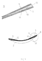
- FIG. 4 A view of the lower edge 3 of the backrest 2 is shown in FIG. 4, and the area B is enlarged on the top.
- the illustration clearly shows how the wedge-shaped insert 11 or 12 lies between the plywood sheets 9, 10. As can be seen, this results in a thickening of the backrest with smooth transitions of the plywood sheets 9, 10, into which thickening a circular cylindrical recess 7 or 8 can be drilled. Since the recesses 7, 8 can run parallel to the surface of the backrest 2 because of the conical part 17 inserted backwards into the chair leg 1 connecting bolt 14, the wall thicknesses around the recesses 7 and 8 need not be made excessively thick, so that Despite the great stability with the thinning wall thickness, the backrest looks elegant.
Landscapes
- Chairs Characterized By Structure (AREA)
- Chair Legs, Seat Parts, And Backrests (AREA)
- Pharmaceuticals Containing Other Organic And Inorganic Compounds (AREA)
Abstract
Description
Eine Modellart, die diese Anforderungen gut erfüllt, sind die Vierbeinstühle mit rohrförmigen Hinterbeinen und einer Rückenlehne aus Sperrholz, wobei die Anbindung der Rückenlehne an die Hinterbeine durch Aufstecken der Rückenlehne auf die oberen Enden der Hinterbeine erfolgt. Dabei müssen aus Stabilitätsgründen die Hinterbeine eine Richtung entgegegengesetzt zur Richtung eines auf dem Stuhl sitzenden, angelehnten Benutzers aufweisen, während die Fläche der aufgesteckten Rückenlehne parallel zum Rücken des Benutzers liegen muß. Das hat zur Folge, daß der Bereich der Anbindung der Rückenlehne an die Hinterbeine ein sehr kritischer Bereich ist, da die Anbindung einerseits extrem stabil sein muß, andererseits aber auch nicht allzu klobig und damit unästhetisch gestaltet werden darf. Hinzukommt, daß die gewählte Konstruktion selbstverständlich immer minimale Kosten in der Produktion erzeugen soll. In einer bekannten Lösung der Firma Lammhults Möbel AB, Lammhult/Schweden, veröffentlicht in der Zeitschrift "md 7/98", werden deshalb bei der Herstellung der Rückenlehne zwischen die Sperrholzblätter an der Unterkante Rundhülsen eingelegt, und beim Preßvorgang die Sperrholzblätter um die Hülsen herum verklebt. Zum Anbinden der Rückenlehne an die Hinterbeine werden diese dann in die an den Stellen der Rundhülsen bestehenden Ausnehmungen eingesteckt.
Diese bekannte Lösung hat jedoch unter anderem den Nachteil, daß der Herstellaufwand nicht unbeachtlich ist, und außerdem das Holz im Bereich der Ausnehmungen eher unstabil ist, da sich aus den kleinen Krümmungsradien der Sperrholzblätter starke Kerbspannungen ergeben.
Hier will die Erfindung Abhilfe schaffen.
Diese Aufgabe wird durch die Merkmale des Anspruchs 1 und der
Unteransprüche gelöst.
Der Kern der Erfindung ist die Idee, durch die keilförmigen Einlagen zwischen den Sperrholzblättern in den unteren äußeren Bereichen der Rückenlehne Verdickungen mit sanften Uebergängen zu schaffen, in die stabile, zur Fläche der Rückenlehne parallele Ausnehmungen für die Verbindungsbolzen gebohrt werden können, und über den konischen Teil des Verbindungsbolzens die notwendige Kippung der Rückenlehne zu den Stuhlbeinen zu ermöglichen.
Die erfindungsgemäße Konstruktion ist nicht nur optimal ansprechend, da die Anbindung unsichtbar ist und die Lehne durch die geringen Dicken in den Mittelbereichen sehr leicht wirkt, sondern auch kostengünstig in Produktion und Montage, aber dennoch stabil und robust beim bestimmungsgemäßen Gebrauch.
- Fig. 1
- die Gesamtdarstellung eines Stuhles mit einer nach der Erfindung gestalteten Rückenlehne,
- Fig.2
- in Explosionsdarstellung einen Schnitt durch den oberen Teil eines Stuhlbeines und des zugehörigen Verbindungsbolzens,
- Fig.3
- eine Draufsicht auf eine Rückenlehne nach der Erfindung im Zustand eines Rohlings, und
- Fig. 4
- eine Draufsicht auf die Unterkante einer Rückenlehne nach der Erfindung mit kreiszylindrischer Ausnehmung.
In Fig. 2 ist die in Fig. 1 dargestellte Anbindung der Rückenlehne 2 an das Stuhlbein 1 nochmals in Explosionsdarstellung und noch mehr im Detail gezeigt: Hier ist insbesondere der Teil der Rückenlehne 2 zu sehen, in dem die Ausnehmungen 7,8 vorgesehen sind. Darunter ist der Verbindungsbozen 14 dargestellt, der einen kreiszylindrischen Teil 15 mit Leimrillen 16, den kugelförmigen Teil 18, und den konischen Teil 17 umfaßt. Außerdem ist der obere Teil des Stuhlbeins 1 im Schnitt gezeigt, wobei die Schrägflächen 19 und die vordere Innenwand des Hinterbeins 1 zu erkennen sind.
In der praktischen Ausführung der Erfindung wird der Verbindungsbolzen 14 in das rohrförmige Hinterbein 1 so eingesteckt, daß der Konus 17 an der vorderen Innenwand 20 des Stuhlbeines 1 anschlägt. Dann wird der Verbindungsbolzen 14 an der Schrägfläche 20 mit dem Bein 1 verlötet. Die Ansatznaht wird dann verschliffen, sodaß sich ein das Bein 1 und den Verbindungsbolzen 14 umfassendes einstückiges Bauteil mit ästhetisch ansprechender glatter Uebergangsnaht ergibt.
Für die Montage wird der Verbindungsbolzen 14 auf seinem kreiszylindrischen Teil 15 mit Leim bestrichen, in die Ausnehmungen 7,8 der Rückenlehne 1 eingesteckt und dort verklebt.
In der Fig.3 ist die Rückenlehne 2 mit Unterkante 3, Außenkanten 4,5, und Oberkante 6 dargestellt. Ferner sind die keilförmigen Einlagen 11,12 angedeutet, die vom dicken zum dünnen Ende von außen nach innen verlaufen.
Da die Ausnehmungen 7,8 wegen des aufgrund seines konischen Teils 17 nach hinten geneigt in das Stuhlbein 1 eingesetzten Verbindungsbolzens 14 parallel zur Fläche der Rückenlehne 2 verlaufen können, müssen die Wandstärken um die Ausnehmungen 7 bzw. 8 herum nicht übermäßig dick ausgeführt werden, sodaß sich trotz großer Stabilität mit der nach innen dünner werdenden Wandstärke ein elegantes Aussehen der Rückenlehne ergibt.
- 1
- Hinterbeine des Stuhls
- 2
- Rückenlehne
- 3
- Unterkante der Rückenlehne
- 4,5
- Außenkanten der Rückenlehne
- 6
- Oberkante der Rückenlehne
- 7,8
- Ausnehmungen
- 9,10
- Sperrholzblätter der Rückenlehne
- 11,12
- keilförmige Einlagen
- 13
- dicke Enden der Keile
- 14
- Verbindungsbolzen
- 15
- kreiszylindrischer Teil
- 16
- Leimrillen
- 17
- konischer Teil
- 18
- kugelförmiger Teil
- 19
- Schrägflächen
- 20
- vordere Innenwand des Hinterbeins
Claims (6)
- Rückenlehne für einen mindestens zwei Hinterbeine (1) umfassenden Stuhl, welche aus Sperrholz besteht und an ihrer Unterkante (4) zwei Ausnehmungen (7,8) für die Anbindung an die Hinterbeine (1) aufweist,
dadurch gekennzeichnet, daß
die Rückenlehne (2) zwischen den Sperrholzblättern (9,10) zwei keilförmige Einlagen (11,12) aus Massivholz aufweist, wobei die beiden Einlagen (11,12) sich symmetrisch von den Außenkanten (4,5) zur Mitte der Rückenlehne (2) hin erstrecken und das dicke Ende (13) des Keils außen liegt, derart, daß sich bei den Ausnehmungen (7,8) die größte Dicke der Rückenlehne (2) befindet. - Rückenlehne nach Anspruch 1, wobei die Ausnehmungen (7,8) einen kreisförmigen Querschnitt aufweisen, und die Hinterbeine (1) des Stuhls rohrförmig mit kreisrundem Querschnitt ausgebildet sind, dadurch gekennzeichnet, daß für die Anbindung der Rückenlehne (2) an die Hinterbeine (1) jeweils ein Verbindungsbolzen (14) vorgesehen ist, der einen kreiszylindrischen Teil (15) zur Aufnahme in den Ausnehmungen(7,8) der Rückenlehne (2), und einen konischen Teil (17) zum Einstecken in die rohrförmigen Hinterbeine (1) aufweist, und zwischen kreiszylindrischen (16) und konischem (17) Teil ein kugelförmiger Teil (18) vorgesehen ist.
- Rückenlehne nach Anspruch 2, dadurch gekennzeichnet, daß die Oberkanten der Hinterbeine (1) nach innen abfallende Schrägflächen (19) aufweisen, deren Neigung der Neigung der Fläche des kugelförmigen Teils (18) des Verbindungsbolzens (14) entspricht.
- Rückenlehne nach Anspruch 2, dadurch gekennzeichnet, daß die Neigung des konischen Teils (17) des Verbindungsbolzens (14) derart ist, daß beim Anschlag des Konus (17) an die vordere Innenwand (20) des Hinterbeins (1) die Rückenlehne (2) parallel zum Rücken des Benutzers des Stuhls liegt.
- Rückenlehne nach Anspruch 3, dadurch gekennzeichnet, daß der kugelförmige Teil (18) des Verbindungsbolzens (14) mit den Schrägflächen (19) der Hinterbeine (1) verlötet sind.
- Rückenlehne nach Anspruch 2, dadurch gekennzeichnet, daß der kreiszylindrische Teil (15) des Verbindungsbolzens (14) auf seiner Außenseite Leimrillen (16) aufweist.
Applications Claiming Priority (2)
| Application Number | Priority Date | Filing Date | Title |
|---|---|---|---|
| DE19842347A DE19842347A1 (de) | 1998-09-16 | 1998-09-16 | Rückenlehne |
| DE19842347 | 1998-09-16 |
Publications (2)
| Publication Number | Publication Date |
|---|---|
| EP0986977A1 true EP0986977A1 (de) | 2000-03-22 |
| EP0986977B1 EP0986977B1 (de) | 2003-04-09 |
Family
ID=7881122
Family Applications (1)
| Application Number | Title | Priority Date | Filing Date |
|---|---|---|---|
| EP99113988A Expired - Lifetime EP0986977B1 (de) | 1998-09-16 | 1999-07-19 | Rückenlehne |
Country Status (4)
| Country | Link |
|---|---|
| EP (1) | EP0986977B1 (de) |
| AT (1) | ATE236553T1 (de) |
| DE (2) | DE19842347A1 (de) |
| ES (1) | ES2193634T3 (de) |
Cited By (1)
| Publication number | Priority date | Publication date | Assignee | Title |
|---|---|---|---|---|
| US7416251B2 (en) | 2005-06-10 | 2008-08-26 | Global Total Office | Chair |
Citations (3)
| Publication number | Priority date | Publication date | Assignee | Title |
|---|---|---|---|---|
| GB492675A (en) * | 1937-03-24 | 1938-09-26 | Cyril Joseph Mortimer | Improvements relating to chairs, tables and like articles of furniture |
| FR2122707A5 (de) * | 1971-01-20 | 1972-09-01 | Chromeplast Sa | |
| US5695244A (en) * | 1995-10-26 | 1997-12-09 | Gillern; Richard | Rocking chair with wood-laminated seat and continuous runners |
Family Cites Families (3)
| Publication number | Priority date | Publication date | Assignee | Title |
|---|---|---|---|---|
| DE848404C (de) * | 1950-10-01 | 1952-09-04 | Baehre Holzwerk G M B H | Stuhlsitz, dessen Ober- und Unterseite durch Lagenholzplatten gebildet werden, und Verfahren zu seiner Herstellung |
| DE1728558U (de) * | 1953-10-03 | 1956-08-23 | Joachim Wegener | Sperrholzsitz. |
| IT225957Y1 (it) * | 1991-04-22 | 1997-03-11 | Italstuhl Spa | Sedia a telaio metallico testata con braccioli schienale e sedile in materia plastica smontabili |
-
1998
- 1998-09-16 DE DE19842347A patent/DE19842347A1/de not_active Withdrawn
-
1999
- 1999-07-19 ES ES99113988T patent/ES2193634T3/es not_active Expired - Lifetime
- 1999-07-19 DE DE59904925T patent/DE59904925D1/de not_active Expired - Fee Related
- 1999-07-19 EP EP99113988A patent/EP0986977B1/de not_active Expired - Lifetime
- 1999-07-19 AT AT99113988T patent/ATE236553T1/de not_active IP Right Cessation
Patent Citations (3)
| Publication number | Priority date | Publication date | Assignee | Title |
|---|---|---|---|---|
| GB492675A (en) * | 1937-03-24 | 1938-09-26 | Cyril Joseph Mortimer | Improvements relating to chairs, tables and like articles of furniture |
| FR2122707A5 (de) * | 1971-01-20 | 1972-09-01 | Chromeplast Sa | |
| US5695244A (en) * | 1995-10-26 | 1997-12-09 | Gillern; Richard | Rocking chair with wood-laminated seat and continuous runners |
Cited By (1)
| Publication number | Priority date | Publication date | Assignee | Title |
|---|---|---|---|---|
| US7416251B2 (en) | 2005-06-10 | 2008-08-26 | Global Total Office | Chair |
Also Published As
| Publication number | Publication date |
|---|---|
| DE59904925D1 (de) | 2003-05-15 |
| DE19842347A1 (de) | 2000-03-23 |
| ATE236553T1 (de) | 2003-04-15 |
| ES2193634T3 (es) | 2003-11-01 |
| EP0986977B1 (de) | 2003-04-09 |
Similar Documents
| Publication | Publication Date | Title |
|---|---|---|
| DE2149542A1 (de) | Sitzmoebel, insbesondere stuhl | |
| DE7802936U1 (de) | Klappstuhl | |
| DE20302612U1 (de) | Liegestuhl | |
| DE69910410T2 (de) | Verstellbarer stuhl | |
| EP0910264A1 (de) | Rahmen für liege- oder sitzmöbel | |
| AT223340B (de) | Stapelbarer Stuhl | |
| EP0986977B1 (de) | Rückenlehne | |
| DE2218022A1 (de) | Stapelbarer stuhl | |
| DE3700321A1 (de) | Rohrgestell, insbesondere stuhl-rohrgestell | |
| DE102004020449B3 (de) | Stapelbarer Objektstuhl aus Holz | |
| CH687663A5 (de) | Tisch. | |
| DE2140384C3 (de) | Klappstuhl | |
| DE20012517U1 (de) | Freischwingerstuhl | |
| DE29605360U1 (de) | Stuhl mit gerundeter Rückenlehne | |
| DE20015547U1 (de) | Möbelstück | |
| DE8815870U1 (de) | Stuhl aus Holz | |
| DE9400591U1 (de) | Sitzmöbel | |
| DE3635811A1 (de) | Stuhl mit einem aus profilen zusammengesetzten stuhlgestell | |
| DE69316002T2 (de) | Klappstuhl | |
| DE4037869A1 (de) | Verbesserung des kreisfoermigen fussstuetzelements fuer stuehle, sitze und hocker, die fuer arbeits- und erholungsraeume geeignet sind | |
| DE9408895U1 (de) | Tisch | |
| DE4143002C1 (en) | Seat for chair, bench - has frame with tubular metal end, with toothing and slots, locked by expanding bolt in timber leg | |
| DE2252929A1 (de) | Zusammensetzbarer stuhl oder sessel | |
| DE19752109A1 (de) | Sitz- oder Liegemöbel | |
| DE2418102A1 (de) | Kunststoff-stuhl |
Legal Events
| Date | Code | Title | Description |
|---|---|---|---|
| PUAI | Public reference made under article 153(3) epc to a published international application that has entered the european phase |
Free format text: ORIGINAL CODE: 0009012 |
|
| AK | Designated contracting states |
Kind code of ref document: A1 Designated state(s): AT BE CH CY DE DK ES FI FR GB GR IE IT LI LU MC NL PT SE |
|
| AX | Request for extension of the european patent |
Free format text: AL;LT;LV;MK;RO;SI |
|
| 17P | Request for examination filed |
Effective date: 20000624 |
|
| AKX | Designation fees paid |
Free format text: AT BE CH CY DE DK ES FI FR GB GR IE IT LI LU MC NL PT SE |
|
| GRAH | Despatch of communication of intention to grant a patent |
Free format text: ORIGINAL CODE: EPIDOS IGRA |
|
| GRAH | Despatch of communication of intention to grant a patent |
Free format text: ORIGINAL CODE: EPIDOS IGRA |
|
| GRAA | (expected) grant |
Free format text: ORIGINAL CODE: 0009210 |
|
| AK | Designated contracting states |
Designated state(s): AT BE CH CY DE DK ES FI FR GB GR IE IT LI LU MC NL PT SE |
|
| PG25 | Lapsed in a contracting state [announced via postgrant information from national office to epo] |
Ref country code: IE Free format text: LAPSE BECAUSE OF NON-PAYMENT OF DUE FEES Effective date: 20030409 Ref country code: FI Free format text: LAPSE BECAUSE OF FAILURE TO SUBMIT A TRANSLATION OF THE DESCRIPTION OR TO PAY THE FEE WITHIN THE PRESCRIBED TIME-LIMIT Effective date: 20030409 |
|
| REG | Reference to a national code |
Ref country code: GB Ref legal event code: FG4D Free format text: NOT ENGLISH |
|
| REG | Reference to a national code |
Ref country code: CH Ref legal event code: EP |
|
| REG | Reference to a national code |
Ref country code: IE Ref legal event code: FG4D Free format text: GERMAN |
|
| PG25 | Lapsed in a contracting state [announced via postgrant information from national office to epo] |
Ref country code: SE Free format text: LAPSE BECAUSE OF FAILURE TO SUBMIT A TRANSLATION OF THE DESCRIPTION OR TO PAY THE FEE WITHIN THE PRESCRIBED TIME-LIMIT Effective date: 20030709 Ref country code: PT Free format text: LAPSE BECAUSE OF FAILURE TO SUBMIT A TRANSLATION OF THE DESCRIPTION OR TO PAY THE FEE WITHIN THE PRESCRIBED TIME-LIMIT Effective date: 20030709 Ref country code: GR Free format text: LAPSE BECAUSE OF FAILURE TO SUBMIT A TRANSLATION OF THE DESCRIPTION OR TO PAY THE FEE WITHIN THE PRESCRIBED TIME-LIMIT Effective date: 20030709 Ref country code: DK Free format text: LAPSE BECAUSE OF FAILURE TO SUBMIT A TRANSLATION OF THE DESCRIPTION OR TO PAY THE FEE WITHIN THE PRESCRIBED TIME-LIMIT Effective date: 20030709 |
|
| PG25 | Lapsed in a contracting state [announced via postgrant information from national office to epo] |
Ref country code: LU Free format text: LAPSE BECAUSE OF NON-PAYMENT OF DUE FEES Effective date: 20030719 Ref country code: CY Free format text: LAPSE BECAUSE OF FAILURE TO SUBMIT A TRANSLATION OF THE DESCRIPTION OR TO PAY THE FEE WITHIN THE PRESCRIBED TIME-LIMIT Effective date: 20030719 |
|
| GBT | Gb: translation of ep patent filed (gb section 77(6)(a)/1977) | ||
| PG25 | Lapsed in a contracting state [announced via postgrant information from national office to epo] |
Ref country code: MC Free format text: LAPSE BECAUSE OF NON-PAYMENT OF DUE FEES Effective date: 20030731 Ref country code: BE Free format text: LAPSE BECAUSE OF NON-PAYMENT OF DUE FEES Effective date: 20030731 |
|
| ET | Fr: translation filed | ||
| REG | Reference to a national code |
Ref country code: ES Ref legal event code: FG2A Ref document number: 2193634 Country of ref document: ES Kind code of ref document: T3 |
|
| REG | Reference to a national code |
Ref country code: IE Ref legal event code: FD4D Ref document number: 0986977E Country of ref document: IE |
|
| BERE | Be: lapsed |
Owner name: *SEDUS STOLL A.G. Effective date: 20030731 |
|
| PLBE | No opposition filed within time limit |
Free format text: ORIGINAL CODE: 0009261 |
|
| STAA | Information on the status of an ep patent application or granted ep patent |
Free format text: STATUS: NO OPPOSITION FILED WITHIN TIME LIMIT |
|
| 26N | No opposition filed |
Effective date: 20040112 |
|
| PGFP | Annual fee paid to national office [announced via postgrant information from national office to epo] |
Ref country code: NL Payment date: 20040630 Year of fee payment: 6 Ref country code: GB Payment date: 20040630 Year of fee payment: 6 |
|
| PGFP | Annual fee paid to national office [announced via postgrant information from national office to epo] |
Ref country code: CH Payment date: 20040702 Year of fee payment: 6 |
|
| PGFP | Annual fee paid to national office [announced via postgrant information from national office to epo] |
Ref country code: AT Payment date: 20040705 Year of fee payment: 6 |
|
| PGFP | Annual fee paid to national office [announced via postgrant information from national office to epo] |
Ref country code: DE Payment date: 20040706 Year of fee payment: 6 |
|
| PGFP | Annual fee paid to national office [announced via postgrant information from national office to epo] |
Ref country code: FR Payment date: 20040708 Year of fee payment: 6 |
|
| PGFP | Annual fee paid to national office [announced via postgrant information from national office to epo] |
Ref country code: ES Payment date: 20040719 Year of fee payment: 6 |
|
| PG25 | Lapsed in a contracting state [announced via postgrant information from national office to epo] |
Ref country code: IT Free format text: LAPSE BECAUSE OF NON-PAYMENT OF DUE FEES Effective date: 20050719 Ref country code: AT Free format text: LAPSE BECAUSE OF NON-PAYMENT OF DUE FEES Effective date: 20050719 |
|
| PG25 | Lapsed in a contracting state [announced via postgrant information from national office to epo] |
Ref country code: ES Free format text: LAPSE BECAUSE OF NON-PAYMENT OF DUE FEES Effective date: 20050720 |
|
| PG25 | Lapsed in a contracting state [announced via postgrant information from national office to epo] |
Ref country code: LI Free format text: LAPSE BECAUSE OF NON-PAYMENT OF DUE FEES Effective date: 20050731 Ref country code: CH Free format text: LAPSE BECAUSE OF NON-PAYMENT OF DUE FEES Effective date: 20050731 |
|
| PG25 | Lapsed in a contracting state [announced via postgrant information from national office to epo] |
Ref country code: NL Free format text: LAPSE BECAUSE OF NON-PAYMENT OF DUE FEES Effective date: 20060201 Ref country code: DE Free format text: LAPSE BECAUSE OF NON-PAYMENT OF DUE FEES Effective date: 20060201 |
|
| REG | Reference to a national code |
Ref country code: CH Ref legal event code: PL |
|
| GBPC | Gb: european patent ceased through non-payment of renewal fee |
Effective date: 20050719 |
|
| PG25 | Lapsed in a contracting state [announced via postgrant information from national office to epo] |
Ref country code: FR Free format text: LAPSE BECAUSE OF NON-PAYMENT OF DUE FEES Effective date: 20060331 |
|
| NLV4 | Nl: lapsed or anulled due to non-payment of the annual fee |
Effective date: 20060201 |
|
| REG | Reference to a national code |
Ref country code: FR Ref legal event code: ST Effective date: 20060331 |
|
| REG | Reference to a national code |
Ref country code: ES Ref legal event code: FD2A Effective date: 20050720 |