EP0987034A2 - Dispositif et méthode pour isoler et récupérer des cellules - Google Patents
Dispositif et méthode pour isoler et récupérer des cellules Download PDFInfo
- Publication number
- EP0987034A2 EP0987034A2 EP99118189A EP99118189A EP0987034A2 EP 0987034 A2 EP0987034 A2 EP 0987034A2 EP 99118189 A EP99118189 A EP 99118189A EP 99118189 A EP99118189 A EP 99118189A EP 0987034 A2 EP0987034 A2 EP 0987034A2
- Authority
- EP
- European Patent Office
- Prior art keywords
- liquid
- filtering member
- objective cell
- recovering
- priming
- Prior art date
- Legal status (The legal status is an assumption and is not a legal conclusion. Google has not performed a legal analysis and makes no representation as to the accuracy of the status listed.)
- Granted
Links
- 238000000034 method Methods 0.000 title claims abstract description 77
- 239000007788 liquid Substances 0.000 claims abstract description 419
- 238000001914 filtration Methods 0.000 claims abstract description 288
- 230000037452 priming Effects 0.000 claims abstract description 171
- 238000003860 storage Methods 0.000 claims abstract description 115
- 238000005406 washing Methods 0.000 claims abstract description 80
- 238000011084 recovery Methods 0.000 claims description 109
- 238000002955 isolation Methods 0.000 claims description 29
- 239000002699 waste material Substances 0.000 claims description 28
- 230000006835 compression Effects 0.000 claims description 21
- 238000007906 compression Methods 0.000 claims description 21
- 230000001154 acute effect Effects 0.000 claims description 12
- 230000000977 initiatory effect Effects 0.000 claims description 5
- 238000007872 degassing Methods 0.000 claims description 4
- 210000004027 cell Anatomy 0.000 description 214
- 210000004698 lymphocyte Anatomy 0.000 description 29
- 239000011148 porous material Substances 0.000 description 28
- 239000000306 component Substances 0.000 description 20
- 230000000052 comparative effect Effects 0.000 description 18
- 229920005597 polymer membrane Polymers 0.000 description 17
- 210000004369 blood Anatomy 0.000 description 15
- 239000008280 blood Substances 0.000 description 15
- 108010088751 Albumins Proteins 0.000 description 11
- 102000009027 Albumins Human genes 0.000 description 11
- 239000000463 material Substances 0.000 description 11
- 239000002504 physiological saline solution Substances 0.000 description 11
- 238000007789 sealing Methods 0.000 description 11
- 238000000926 separation method Methods 0.000 description 11
- 238000002474 experimental method Methods 0.000 description 10
- 210000003743 erythrocyte Anatomy 0.000 description 9
- 230000001965 increasing effect Effects 0.000 description 9
- 238000003825 pressing Methods 0.000 description 8
- 239000000725 suspension Substances 0.000 description 7
- 230000002093 peripheral effect Effects 0.000 description 6
- 125000006850 spacer group Chemical group 0.000 description 6
- 210000000130 stem cell Anatomy 0.000 description 6
- 239000000203 mixture Substances 0.000 description 5
- 229920002635 polyurethane Polymers 0.000 description 5
- 239000004814 polyurethane Substances 0.000 description 5
- 238000005086 pumping Methods 0.000 description 5
- 239000000126 substance Substances 0.000 description 5
- 238000005119 centrifugation Methods 0.000 description 4
- 230000008859 change Effects 0.000 description 4
- 239000003153 chemical reaction reagent Substances 0.000 description 4
- 230000007547 defect Effects 0.000 description 4
- KRKNYBCHXYNGOX-UHFFFAOYSA-N citric acid Chemical compound OC(=O)CC(O)(C(O)=O)CC(O)=O KRKNYBCHXYNGOX-UHFFFAOYSA-N 0.000 description 3
- 238000010276 construction Methods 0.000 description 3
- 230000005484 gravity Effects 0.000 description 3
- -1 polypropylene Polymers 0.000 description 3
- 239000004800 polyvinyl chloride Substances 0.000 description 3
- 229920000915 polyvinyl chloride Polymers 0.000 description 3
- 239000004743 Polypropylene Substances 0.000 description 2
- 241000700605 Viruses Species 0.000 description 2
- 230000001133 acceleration Effects 0.000 description 2
- 238000004458 analytical method Methods 0.000 description 2
- 230000008901 benefit Effects 0.000 description 2
- 210000001124 body fluid Anatomy 0.000 description 2
- 239000010839 body fluid Substances 0.000 description 2
- 238000000432 density-gradient centrifugation Methods 0.000 description 2
- 230000002542 deteriorative effect Effects 0.000 description 2
- 238000010586 diagram Methods 0.000 description 2
- 238000007599 discharging Methods 0.000 description 2
- 230000000694 effects Effects 0.000 description 2
- 239000013013 elastic material Substances 0.000 description 2
- 229920001971 elastomer Polymers 0.000 description 2
- 230000002708 enhancing effect Effects 0.000 description 2
- 230000002255 enzymatic effect Effects 0.000 description 2
- 230000004927 fusion Effects 0.000 description 2
- 238000010030 laminating Methods 0.000 description 2
- 238000005259 measurement Methods 0.000 description 2
- 239000012528 membrane Substances 0.000 description 2
- 239000008363 phosphate buffer Substances 0.000 description 2
- 229920001155 polypropylene Polymers 0.000 description 2
- 238000003672 processing method Methods 0.000 description 2
- 239000011347 resin Substances 0.000 description 2
- 229920005989 resin Polymers 0.000 description 2
- 239000005060 rubber Substances 0.000 description 2
- 238000005070 sampling Methods 0.000 description 2
- 238000004062 sedimentation Methods 0.000 description 2
- 238000002560 therapeutic procedure Methods 0.000 description 2
- 238000012546 transfer Methods 0.000 description 2
- 108010077544 Chromatin Proteins 0.000 description 1
- 239000004952 Polyamide Substances 0.000 description 1
- 239000004721 Polyphenylene oxide Substances 0.000 description 1
- 239000004372 Polyvinyl alcohol Substances 0.000 description 1
- 230000004075 alteration Effects 0.000 description 1
- 239000003146 anticoagulant agent Substances 0.000 description 1
- 229940127219 anticoagulant drug Drugs 0.000 description 1
- 239000000427 antigen Substances 0.000 description 1
- 108091007433 antigens Proteins 0.000 description 1
- 102000036639 antigens Human genes 0.000 description 1
- 230000001174 ascending effect Effects 0.000 description 1
- 238000004500 asepsis Methods 0.000 description 1
- 238000003556 assay Methods 0.000 description 1
- 239000012503 blood component Substances 0.000 description 1
- 210000001772 blood platelet Anatomy 0.000 description 1
- 239000007853 buffer solution Substances 0.000 description 1
- 210000002390 cell membrane structure Anatomy 0.000 description 1
- 210000003855 cell nucleus Anatomy 0.000 description 1
- 210000003850 cellular structure Anatomy 0.000 description 1
- 210000001175 cerebrospinal fluid Anatomy 0.000 description 1
- 210000003483 chromatin Anatomy 0.000 description 1
- 210000000349 chromosome Anatomy 0.000 description 1
- 239000007979 citrate buffer Substances 0.000 description 1
- 238000003776 cleavage reaction Methods 0.000 description 1
- 238000007796 conventional method Methods 0.000 description 1
- 238000005138 cryopreservation Methods 0.000 description 1
- 239000002577 cryoprotective agent Substances 0.000 description 1
- 230000000959 cryoprotective effect Effects 0.000 description 1
- 230000002950 deficient Effects 0.000 description 1
- 230000005684 electric field Effects 0.000 description 1
- 230000008030 elimination Effects 0.000 description 1
- 238000003379 elimination reaction Methods 0.000 description 1
- 210000004700 fetal blood Anatomy 0.000 description 1
- 239000000706 filtrate Substances 0.000 description 1
- 238000002825 functional assay Methods 0.000 description 1
- 238000001415 gene therapy Methods 0.000 description 1
- 238000009499 grossing Methods 0.000 description 1
- 238000011134 hematopoietic stem cell transplantation Methods 0.000 description 1
- 238000009169 immunotherapy Methods 0.000 description 1
- 238000000338 in vitro Methods 0.000 description 1
- 230000036512 infertility Effects 0.000 description 1
- 239000004615 ingredient Substances 0.000 description 1
- 210000002751 lymph Anatomy 0.000 description 1
- 238000012423 maintenance Methods 0.000 description 1
- 238000004519 manufacturing process Methods 0.000 description 1
- 230000007246 mechanism Effects 0.000 description 1
- 230000002503 metabolic effect Effects 0.000 description 1
- 239000004745 nonwoven fabric Substances 0.000 description 1
- 210000003463 organelle Anatomy 0.000 description 1
- 238000005192 partition Methods 0.000 description 1
- 239000003058 plasma substitute Substances 0.000 description 1
- 229920002647 polyamide Polymers 0.000 description 1
- 239000004417 polycarbonate Substances 0.000 description 1
- 229920000515 polycarbonate Polymers 0.000 description 1
- 229920000570 polyether Polymers 0.000 description 1
- 229920002451 polyvinyl alcohol Polymers 0.000 description 1
- 238000004321 preservation Methods 0.000 description 1
- 230000008569 process Effects 0.000 description 1
- 239000000047 product Substances 0.000 description 1
- 230000001737 promoting effect Effects 0.000 description 1
- 230000009467 reduction Effects 0.000 description 1
- 230000007017 scission Effects 0.000 description 1
- 230000001954 sterilising effect Effects 0.000 description 1
- 238000004659 sterilization and disinfection Methods 0.000 description 1
- 229920003048 styrene butadiene rubber Polymers 0.000 description 1
- 230000004083 survival effect Effects 0.000 description 1
- 238000012360 testing method Methods 0.000 description 1
- 229920002725 thermoplastic elastomer Polymers 0.000 description 1
- 210000001519 tissue Anatomy 0.000 description 1
- 238000011144 upstream manufacturing Methods 0.000 description 1
- 239000002759 woven fabric Substances 0.000 description 1
Images

Classifications
-
- B—PERFORMING OPERATIONS; TRANSPORTING
- B01—PHYSICAL OR CHEMICAL PROCESSES OR APPARATUS IN GENERAL
- B01D—SEPARATION
- B01D69/00—Semi-permeable membranes for separation processes or apparatus characterised by their form, structure or properties; Manufacturing processes specially adapted therefor
- B01D69/12—Composite membranes; Ultra-thin membranes
-
- A—HUMAN NECESSITIES
- A61—MEDICAL OR VETERINARY SCIENCE; HYGIENE
- A61M—DEVICES FOR INTRODUCING MEDIA INTO, OR ONTO, THE BODY; DEVICES FOR TRANSDUCING BODY MEDIA OR FOR TAKING MEDIA FROM THE BODY; DEVICES FOR PRODUCING OR ENDING SLEEP OR STUPOR
- A61M1/00—Suction or pumping devices for medical purposes; Devices for carrying-off, for treatment of, or for carrying-over, body-liquids; Drainage systems
- A61M1/02—Blood transfusion apparatus
- A61M1/0209—Multiple bag systems for separating or storing blood components
- A61M1/0218—Multiple bag systems for separating or storing blood components with filters
-
- A—HUMAN NECESSITIES
- A61—MEDICAL OR VETERINARY SCIENCE; HYGIENE
- A61M—DEVICES FOR INTRODUCING MEDIA INTO, OR ONTO, THE BODY; DEVICES FOR TRANSDUCING BODY MEDIA OR FOR TAKING MEDIA FROM THE BODY; DEVICES FOR PRODUCING OR ENDING SLEEP OR STUPOR
- A61M1/00—Suction or pumping devices for medical purposes; Devices for carrying-off, for treatment of, or for carrying-over, body-liquids; Drainage systems
- A61M1/02—Blood transfusion apparatus
- A61M1/0209—Multiple bag systems for separating or storing blood components
- A61M1/0236—Multiple bag systems for separating or storing blood components with sampling means, e.g. sample bag or sampling port
-
- A—HUMAN NECESSITIES
- A61—MEDICAL OR VETERINARY SCIENCE; HYGIENE
- A61M—DEVICES FOR INTRODUCING MEDIA INTO, OR ONTO, THE BODY; DEVICES FOR TRANSDUCING BODY MEDIA OR FOR TAKING MEDIA FROM THE BODY; DEVICES FOR PRODUCING OR ENDING SLEEP OR STUPOR
- A61M1/00—Suction or pumping devices for medical purposes; Devices for carrying-off, for treatment of, or for carrying-over, body-liquids; Drainage systems
- A61M1/36—Other treatment of blood in a by-pass of the natural circulatory system, e.g. temperature adaptation, irradiation ; Extra-corporeal blood circuits
- A61M1/3621—Extra-corporeal blood circuits
- A61M1/3627—Degassing devices; Buffer reservoirs; Drip chambers; Blood filters
- A61M1/3633—Blood component filters, e.g. leukocyte filters
-
- A—HUMAN NECESSITIES
- A61—MEDICAL OR VETERINARY SCIENCE; HYGIENE
- A61M—DEVICES FOR INTRODUCING MEDIA INTO, OR ONTO, THE BODY; DEVICES FOR TRANSDUCING BODY MEDIA OR FOR TAKING MEDIA FROM THE BODY; DEVICES FOR PRODUCING OR ENDING SLEEP OR STUPOR
- A61M1/00—Suction or pumping devices for medical purposes; Devices for carrying-off, for treatment of, or for carrying-over, body-liquids; Drainage systems
- A61M1/36—Other treatment of blood in a by-pass of the natural circulatory system, e.g. temperature adaptation, irradiation ; Extra-corporeal blood circuits
- A61M1/3621—Extra-corporeal blood circuits
- A61M1/3643—Priming, rinsing before or after use
- A61M1/3644—Mode of operation
-
- B—PERFORMING OPERATIONS; TRANSPORTING
- B01—PHYSICAL OR CHEMICAL PROCESSES OR APPARATUS IN GENERAL
- B01D—SEPARATION
- B01D61/00—Processes of separation using semi-permeable membranes, e.g. dialysis, osmosis or ultrafiltration; Apparatus, accessories or auxiliary operations specially adapted therefor
- B01D61/14—Ultrafiltration; Microfiltration
-
- B—PERFORMING OPERATIONS; TRANSPORTING
- B01—PHYSICAL OR CHEMICAL PROCESSES OR APPARATUS IN GENERAL
- B01D—SEPARATION
- B01D69/00—Semi-permeable membranes for separation processes or apparatus characterised by their form, structure or properties; Manufacturing processes specially adapted therefor
- B01D69/02—Semi-permeable membranes for separation processes or apparatus characterised by their form, structure or properties; Manufacturing processes specially adapted therefor characterised by their properties
-
- A—HUMAN NECESSITIES
- A61—MEDICAL OR VETERINARY SCIENCE; HYGIENE
- A61M—DEVICES FOR INTRODUCING MEDIA INTO, OR ONTO, THE BODY; DEVICES FOR TRANSDUCING BODY MEDIA OR FOR TAKING MEDIA FROM THE BODY; DEVICES FOR PRODUCING OR ENDING SLEEP OR STUPOR
- A61M1/00—Suction or pumping devices for medical purposes; Devices for carrying-off, for treatment of, or for carrying-over, body-liquids; Drainage systems
- A61M1/36—Other treatment of blood in a by-pass of the natural circulatory system, e.g. temperature adaptation, irradiation ; Extra-corporeal blood circuits
- A61M1/3621—Extra-corporeal blood circuits
- A61M1/3643—Priming, rinsing before or after use
-
- A—HUMAN NECESSITIES
- A61—MEDICAL OR VETERINARY SCIENCE; HYGIENE
- A61M—DEVICES FOR INTRODUCING MEDIA INTO, OR ONTO, THE BODY; DEVICES FOR TRANSDUCING BODY MEDIA OR FOR TAKING MEDIA FROM THE BODY; DEVICES FOR PRODUCING OR ENDING SLEEP OR STUPOR
- A61M2202/00—Special media to be introduced, removed or treated
- A61M2202/04—Liquids
- A61M2202/0413—Blood
- A61M2202/0439—White blood cells; Leucocytes
-
- A—HUMAN NECESSITIES
- A61—MEDICAL OR VETERINARY SCIENCE; HYGIENE
- A61M—DEVICES FOR INTRODUCING MEDIA INTO, OR ONTO, THE BODY; DEVICES FOR TRANSDUCING BODY MEDIA OR FOR TAKING MEDIA FROM THE BODY; DEVICES FOR PRODUCING OR ENDING SLEEP OR STUPOR
- A61M2205/00—General characteristics of the apparatus
- A61M2205/75—General characteristics of the apparatus with filters
- A61M2205/7554—General characteristics of the apparatus with filters with means for unclogging or regenerating filters
Definitions
- This invention relates to an apparatus and method for isolating and recovering an objective cell intended to obtain from a liquid to be treated.
- an objective cell such as lymphocyte from other components and subsequent concentration of the objective cell
- the method for isolating cell can be roughly classified into (1) a method based on differences in specific density of cells, such as a sedimentation method, a centrifugation method and a density gradient centrifugation method; (2) an electric separation method based on the surface electric charge of cells; (3) an affinity separation method taking advantage of the antibody specific to the surface antigen of the cells; and (4) a filtering separation method based on the differences in size and in deformability of cells.
- centrifugation method which is generally employed as a method for treating a large quantity of cells.
- this centrifugation method requires a large-scaled and expensive apparatus for an aseptic treatment and recovery of cells, and since differences in density among cells are not so large, the types of cells that can be separated are inevitably restricted.
- the objective cell may be badly damaged.
- the affinity separation method (3) is most excellent in view of specificity among the aforementioned various isolation methods.
- an enzymatic treatment for cleavage an antibody molecule combined to the cell is required. Therefore, it will be confronted with technical problems such as the generation of damage to the objective cell due to the enzymatic treatment, a troublesome operation and the maintenance of the activity of antibody. Additionally, since it employs an expensive antibody, the cost for the isolation of cell will be increased, thus making the method inappropriate for a prompt treatment of a large amount of cells.
- the filtering separation method (4) is featured in that it comprises the steps of passing a suspension liquid containing an objective cell through a filtering member so as to capture the objective cell on the filtering member, passing recovering liquid through the filtering member in the direction opposite to that of the capturing step so as to remove the objective cell captured on the filtering member, and recovering the objective cell.
- this filtering separation method is suited for promptly separating a large quantity of objective cell from the unwanted cells as well as from unwanted liquid components, this method is defective in that the recovery ratio of the objective cell is low. This defect can be ascribed to the fact that the fine pore diameter of the filtering member is constant throughout a sequence of the treatment procedures.
- the pore size of the filtering member when the pore size of the filtering member is set relatively larger with a view to improve the releasability of the objective cell at the step of recovering, the amount of the objective cell that passes through the filtering member without being captured by the filtering member will be increased.
- the pore size of the filtering member is set relatively smaller, the amount of the objective cell that passes through the filtering member will be minimized, thereby increasing the quantity of objective cell that can be captured by the filtering member.
- the adhesivity of the objective cell to the fine pore of the filtering member will be increased so that the releasability of the objective cell at the step of recovering the objective cell will be deteriorated, thus making it impossible to recover the objective cell at a high yield.
- the removability of unwanted cells will be also deteriorated.
- a filtering member having a suitable pore size which is capable of satisfying not only the capturability but also the releasability of the objective cell is required to be selected.
- this filtering separation method it is possible in this filtering separation method to decrease more or less the quantity of the objective cell that passes through the filtering member and to increase the capturing ratio of the objective cell by reducing the quantity of feeding the suspension of cells on the occasion of the filtration.
- the feeding quantity of the suspension of cells is reduced, the throughput per unit time of the suspension of cells is also caused to decrease, thus spoiling the advantage of the filtering separation method, i.e. a prompt treatment of large quantity of the suspension of cells.
- the prior arts have the merits and demerits in the means for isolating the objective cell from the unwanted components as well as in the means for recovering the isolated cell.
- the aforementioned methods have been suitably selected or suitably combined depending on the purpose and the required level of isolation.
- the objects of the present invention are to provide an apparatus and method for easily and aseptically treating a suspension of cells so as to isolate and recover an objective cell, without deteriorating the quality and characteristics of the objective cell.
- FIG. 1 represents a circuit diagram illustrating one embodiment of the cell isolating and recovering apparatus according to this invention.
- the cell isolating and recovering apparatus comprises a filtering device 2; a first line 3 for feeding a priming liquid to the filtering device 2; a second line 4 for feeding a liquid to be treated containing the objective cell intended to be isolated to the filtering device 2; a third line 5 provided with a storage container 52 for storing the priming liquid that has been passed through the filtering device 2; a fourth line 6 for discharging a waste liquid such as the liquid to be treated that has passed through the filtering device 2; a first connector 7 for connecting the second line 4 and the third line 5 so as to communicate them with the filtering device 2; and a second connector 8 for connecting the first line 3 and the fourth line 6 so as to communicate them with the filtering device 2.
- One end (a first port 2211 to be illustrated hereinafter) of the filtering device 2 is connected with a third branch tube 73 of the first connector 7, and the other end (a second port 2221 to be illustrated hereinafter) of the filtering device 2 is connected with a second branch tube 82 of the second connector 8.
- This filtering device 2 is designed to capture an objective cell intended to be isolated and recovered (hereinafter referred to as "objective cell”) from a liquid to be treated which will be described hereinafter, and to release the objective cell thus captured therein.
- object cell an objective cell intended to be isolated and recovered
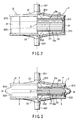
- the filtering device 2 is composed of a housing 22, a filtering member 21 placed in the housing 22, flow passage-securing members 23a and 23b, and a sealing member 24.
- the filtering member 21 is formed of a laminate consisting of a plurality of porous polymer membranes 211.
- Each porous polymer membrane 211 is preferably made of an elastic material which is hardly capable of being plastically deformed by an external force such as compression or extension and is capable of restoring it original configuration as the external force is removed.
- Specific examples of the porous polymer membrane 211 are a porous body of high molecular materials such as polyurethane, styrene-butadiene rubber, polyvinyl alcohol, polypropylene, polyether polyamide, etc.
- each porous polymer membrane 211 of the filtering member 21 When the filtering member 21 is in a compressed state as a predetermined compressive force is applied to the filtering member 21 as shown in FIG. 3, each porous polymer membrane 211 of the filtering member 21 according to this embodiment is compacted or densified, so that the porosity of each porous polymer membrane 211 becomes a first porosity which is lower in porosity than a second porosity to be described hereinafter.
- This first porosity is suited for capturing and isolating the objective cell.
- the porosity of each porous polymer membrane 211 takes a second porosity which is suited for releasing the objective cell that has been captured by the filtering member 21.
- the ratio of the second porosity to the first porosity in this case may be suitably determined depending on the various conditions such as the types and size of the objective cell.
- the second porosity should preferably be about 1.05 to 3 times, more preferably about 1.10 to 2.0 times as high as the first porosity. If the ratio of the second porosity to the first porosity is smaller than this lower limit, there is a possibility that the effect of improving the yield of the objective cell through the alteration of porosity may not be sufficiently achieved, depending on the types and size of the objective cell.
- the first porosity becomes lower than 33%, so that the passage of the liquid to be treated containing the objective cell through the porous polymer membrane 211 may be badly deteriorated. If the average pore diameter of the filtering
- first pore size when the objective cell is lymphocyte, the first pore size should preferably be less than 5 ⁇ m, more preferably in the range of 2 to 4.9 ⁇ m, while the second pore size should preferably be not less than 5 ⁇ m, more preferably not less than 6 ⁇ m.
- the filtering member 21 may be formed of a plurality of the same porous polymer membranes 211, it is more preferable that porous polymer membranes 211 constituting the filtering member 21 has a gradient in physical or chemical properties, or especially, all or some of the porous polymer membranes 211 are provided with different physical or chemical properties from the other porous polymer membranes 211. It is possible due to this difference in physical or chemical properties to enhance the capturability of the objective cell and/or the releasability of the objective cell on the occasion of the recovering.
- the physical or chemical properties to be provided with a gradient can be suitably determined based on a condition such as the type, size and property of the objective cell, so that the capturability of the objective cell by the filtering member and/or the releasability of the objective cell on the occasion of the recovery can be improved due to the provision of this gradient.
- the gradient is realized by, for-example, a structure in which the porous polymer membrane are stacked in such a manner that at least any one of the porosity, average pore diameter, zeta-potential and hydrophilicity is changed continuously or stepwise in the direction along which the liquid to be treated are allowed to flow.
- the laminated structure wherein the porosity is gradually changed use may be made of the construct in which the porous polymer membranes 211 are laminated so as to cause the porosity to become gradually smaller in the direction from the first port 2211 side to the second port 2221 side as described hereinafter.
- the porous polymer membranes 211 are laminated so as to cause the average pore diameter to become gradually smaller in the direction from the first port 2211 side to the second port 2221 side as described hereinafter.
- the laminated structure wherein the hydrophilicity is gradually changed a method of successively laminating the porous polymer membranes 211 so as to cause the hydrophilicity to become gradually enhanced in the direction from the first port 2211 side to the second port 2221 side may be adopted.
- the directivity or orientation of these gradients is not limited to the aforementioned examples, but may be optionally altered depending on the types of objective cell.
- the filtering member 21 is provided on both surfaces thereof with the flow passage securing members 23a and 23b, respectively, and is placed together with these flow passage securing members 23a and 23b in the housing 22.
- Each of the flow passage securing members 23a and 23b is constituted by a polycarbonate spacer 232 having through-holes for preventing the spacer 232 from being distorted on the occasion of compression for instance, and by a mesh (not shown) which is interposed between the spacer 232 and the filtering member 21.
- a space communicating with the first port 2211 is secured on the inside of the rib 2212 to be explained hereinafter, thereby securing a passageway through which the liquid entering from the first port 2211 can flow toward the filtering member 21.
- a space communicating with the second port 2221 is secured on the inside of the rib 2212, thereby securing a passageway through which the liquid entering from the second port 2221 can flow toward the filtering member 21.
- the filtering member 21 is mounted inside the housing 22 in such a manner as to partition the housing 22 into a space communicating with the first port 2211 and a space communicating with the second port 2221.
- the liquid passing through the inner space of the rib 2212 can be uniformly dispersed all over the filtering member 21, thus making it possible to enhance the efficiency in the filtration, washing and recovery of the objective cell.
- the housing 22 is composed of a first housing member 221 and a second housing member 222, which are formed symmetrical with each other.
- the first housing 221 is provided at the center thereof with a projected first port 2211 communicating with the interior of the housing 22 and constituting an inflow port for liquid to be treated.
- the second housing 222 is provided at the center thereof with a projected second port 2221 communicating with the interior of the housing 22 and constituting a filtrate outflow port.
- the first housing 221 is also provided therein with a plurality of plate-like ribs 2212 pressing the flow passage securing member 23a for compressing the filtering member 21.
- the second housing 222 is also provided therein with a plurality of plate-like ribs 2222 pressing the flow passage securing member 23b for compressing the filtering member 21.
- These plurality of plate-like ribs 2212 and 2222 are respectively formed radially extending from the central axis of the housing 22.
- the upper inner wall of the first housing 221 is converged toward the first port 2211 thereby forming a funnel-like configuration, thus enabling air bubble to float upward along this funnel-like inner wall on the occasion of priming to be explained hereinafter, and improving the discharge of the air bubble.
- the lower inner wall of the second housing 222 is converged toward the second port 2221 thereby forming a funnel-like configuration, thus smoothing the liquid flow inside the housing 22, in particular, enabling the liquid to be smoothly discharged from the second port 2221.
- the first housing 221 is also provided at the outer peripheral portion thereof with an annular rib 2213 for fixing a sealing member 24 in place.
- the second housing 222 is also provided at the outer peripheral portion thereof with an annular rib 2223 for fixing the sealing member 24 in place.
- These annular ribs 2213 and 2223 are extended to face to each other.
- the housing 22 is provided at the outer peripheral portion thereof with a cylindrical sealing member 24.
- This sealing member 24 is formed of an elastic material such as rubber of various types or a thermoplastic elastomer and is adhered or fuse-bonded through the opposite end portions thereof (in the axial direction thereof) to the annular ribs 2213 and 2223, thus liquid-tightly fixing the sealing member 24 to the housing 22.
- annular ribs 2213 and 2223 are designed to strongly press the peripheral portion of each porous polymer membrane 211 when the filtering member 21 is in a compressed state. Therefore, when the filtering member 21 is in a compressed state, the liquid to be treated passing through the filter device 2 is inhibited from passing beyond the annular ribs 2213 and 2223 to the outer periphery of the filtering member 21.
- the sealing member 24 When the filtering member 21 is a non-compressed state as shown in FIG. 2, the sealing member 24 is kept approximately in a cylindrical configuration. However, when a compression force P is applied to the housing 22, the filtering member 21 is turned into a compressed state as shown in FIG. 3, thereby causing a middle portion (in the axial direction) of the sealing member 24 to become deformed or protruded externally.
- the sealing member 24 By mounting the sealing member 24 in this manner, the liquid-tightness and in particular, the asepsis of the housing 22 is ensured irrespective of the compressed or non-compressed state of the filtering member 21.
- the configuration of the sealing member 24 is not limited to that shown in these FIGS., but may be of a bellows-like configuration. Further, the sealing member 24 may be fixed inside the annular ribs 2213 and 2223.
- a mechanism comprising a pair of pressing members which can be moved close to each other or spaced apart from each other through the movement of at least one of the pressing members, and means for driving the pressing members to move as mentioned above can be employed for instance.
- the filter device 2 is interposed between these pressing members of the porosity-changing means, and then, these pressing members are moved close to each other, thus applying a compression force P to the housing 22 of the filter device 2, thereby compressing the filtering member 21 placed inside the housing 22.
- the compression force P that has been applied to the housing 22 can be relieved, thereby relieving the compression of the filtering members 21 placed inside the housing 22.
- a first line 3 is composed of a first tube 30, a first clamp 31 and a first bottle-puncturing needle 32.
- One end of the first tube 30 is connected with a first branch tube 81 of the second connector 8, and the other end of the first tube 30 is connected with the first bottle-puncturing needle 32.
- the first bottle-puncturing needle 32 is designed to pierce into an elastic plug of a container in which a priming liquid (not shown) is stored (hereinafter referred to as a priming liquid-storage container), thereby connecting the first line 3 with the priming liquid-storage container.
- a priming liquid-storage container a container in which a priming liquid (not shown) is stored
- a recovery liquid for recovering the objective cell captured by the filter device 2 can be fed from the priming liquid-storage container, via the first bottle-puncturing needle 32, the first tube 30 and the second connector 8, to the filter device 2.
- the first line 3 is capable of not only feeding a priming liquid to the filter device 2 but also feeding a recovery liquid to the filter device 2.
- the first tube 30 is formed of a material which is excellent in flexibility and pliability, suited to be closed or opened by means of a clamp, and also suited for sterilization, a specific example thereof being soft polyvinyl chloride.
- a second tube 40, a third tube 50 and a fourth tube 60 which will be explained below are also formed of the same kind of material as that of the first tube 30.
- the filtering member 21 of the filter device 2 can be impregnated with the priming liquid.
- a physiological saline a physiological saline
- a buffer solution such as a phosphate buffer and a citrate buffer
- a culture liquid such as a phosphate buffer and a citrate buffer
- a specific gravity liquid such as a plasma expander
- any one of these liquids to which albumin or plasma is added can be employed.
- the priming liquid should preferably be selected from those having composition which are close to those of plasma.
- Preferable examples thereof are a physiological saline, a phosphate buffer, a culture liquid, and any one of these liquids to which albumin or plasma is added.
- the recovery liquid there is no particular limitation as long as it is capable of recovering an objective cell from the filter device 2.
- a liquid which is similar in composition to the priming liquid, or a cryoprotective liquid can be employed.
- the recovery liquid should preferably be a liquid which contains albumin, such as an albumin-containing physiological saline. Because when albumin is included in a recovery liquid, the release of lymphocyte or hematopietic stem/progenitor cell from the filtering member 21 can be facilitated.
- a recovery liquid is the same type as a priming liquid. If a recovery liquid is formulated in this manner, the priming liquid stored in the priming liquid storage container can be employed as a recovery liquid by simply operating the first clamp 31 as explained hereinafter. Namely, the priming liquid storage container can be employed also as a container for feeding a recovery liquid.
- the first tube 30 is provided at the intermediate portion thereof with a first clamp 31 as means for opening or closing the passage of liquid therethrough.
- the first tube 30 can be closed or opened so as to introduce a required volume of the priming liquid or recovering liquid into the first tube 30 as required. Further, by closing the first tube 30 by means of this first clamp 31, the liquid to be treated which will be explained later can be prevented from flowing into the other end of the first tube 30, i.e. toward the first bottle-puncturing needle 32.
- the third line 5 is composed of a third tube 50, a third clamp 51 and a storage container 52. One end of the third line 5 is connected with a first branch tube 71 of the first connector 7. The other end of the third tube 50 is connected with a storage container 52.
- the priming liquid When a priming liquid is fed to the filter device 2, the priming liquid is allowed to enter into the filter device 2 from the second port 2221, thus filling the interior of the housing 22 with the priming liquid, and impregnating the filtering member 21 with the priming liquid.
- the excessive amount of the priming liquid overflows from the first port 2211, thus causing the excessive amount of the priming liquid to pass through the third tube 50 into the storage container 52, and allowing the priming liquid to be stored in the storage container 52.
- this excessive amount of the priming liquid stored in the storage container 52 is then employed as a washing liquid on the occasion of washing the filter device 2. Further, this storage container 52 is also capable of recovering therein a recovery liquid passed through the filter device 2 and containing an objective cell. Namely, this storage container 52 is designed in such a manner that it is capable of not only storing an excessive quantity of priming liquid but also recovering a recovery liquid containing an objective cell.
- the third tube 50 acts not only as a passageway for introducing an excessive quantity of priming liquid that has been flown out of the first port 2211 into the storage container 52, but also as a passageway for feeding a washing liquid to the filter device 2. Further, the third tube 50 can be used also as a passageway for a recovery liquid passed through the filter device 2 and containing an objective cell.
- an excessive quantity of the priming liquid that has flown out of the first port 2211 can be employed subsequently as a washing liquid, thereby making it unnecessary to newly prepare a washing liquid for washing the filter device 2.
- the cell-isolating and recovering apparatus 1 Since the cell-isolating and recovering apparatus 1 is no more required to provide it with an inlet port for introducing a washing liquid, it can be more simplified in construction as compared with the conventional apparatus and can be manufactured at lower cost as compared with the conventional apparatus.
- the storage container 52 is formed of a bag made of a flexible soft resin sheet, such as a polyvinyl chloride sheet, whose peripheral portions are overlapped and adhered or fusion-bonded with each other so as to form the bag.
- a flexible soft resin sheet such as a polyvinyl chloride sheet
- the storage container 52 is provided at the upper periphery thereof with an opening portion 521 consisting of a short tube having a sealed distal end and covered entirely with a case sheet which is openable by a peel tub. Namely, this short tube can be exposed by pulling the peel tub to open the case sheet.
- this exposed short tube is communicated with a needle tube by piercing the needle tube into the short tube, it is possible to perform the sampling of a recovery liquid containing an objective cell from the storage container 52.
- the recovering liquid thus sampled is then subjected to various kinds of test and analysis such as virus check and the functional assay of cell.
- the storage container 52 is further provided at the upper periphery thereof with a recovery liquid-withdrawing tube 522.
- the distal end of this recovery liquid-withdrawing tube 522 is sealed by means of fusion bond for instance.
- This recovering liquid-withdrawing tube 522 can be sterilely connected with another tube by making use of a sterile tube-connecting device (Japanese Utility Model Unexamined Publication H6-26877), thereby making it possible to transfer the recovery liquid stored in the storage container 52 to a separate container communicated with said another tube through this connection between the recovery liquid-withdrawing tube 522 and said another tube.
- the third tube 50 is provided at the intermediate portion thereof with a third clamp 51 as means for opening or closing the passage of liquid through the tube.
- the third tube 50 can be closed or opened so as to introduce a washing liquid into the third tube 50 as required. It is also possible to introduce a recovery liquid into the storage container 52 in the same manner as mentioned above. Further, by closing the third tube 50 by means of this third clamp 51, the liquid to be treated can be prevented from flowing into the storage container 52.
- the second line 4 is composed of a second tube 40, a second clamp 41 and a second bottle-puncturing needle 42.
- One end of the second tube 40 is connected with a second branch tube 72 of the first connector 7.
- the other end of the second tube 40 is connected with the second bottle-puncturing needle 42.
- the second line 4 can be connected with a container (not shown) in which a liquid to be treated is stored (hereinafter referred to as a storage container of liquid to be treated) by piercing the second bottle-puncturing needle 42 into an elastic plug of the storage container of liquid to be treated.
- a storage container of liquid to be treated a liquid to be treated in which a liquid to be treated is stored
- the liquid to be treated containing an objective cell for isolation can be fed from the storage container to the filter device 2, via the second bottle-puncturing needle 42, the second tube 40 and the first connector 7.
- the liquid to be treated which is applied to the cell-isolating and recovering apparatus there is no particular limitation as long as it contains an objective cell that can be isolated by the filter device 2.
- body fluids such as blood, lymph, cerebrospinal fluid and cord blood; a treated body fluid such as a blood component (such as plasma and buffy coat); and a suspension of cell may be employed.
- a cell such as lymphocyte (entire cells of lymphocyte or a specific type thereof) or hematopietic stem/progenitor cell may be applicable to in this invention.
- the cell in this invention includes not only the aforementioned cells but also living microorgan tissues such as cell nucleus, chromosome, chromatin, cell membrane structure, organelle, etc.
- the second tube 40 is provided at the intermediate portion thereof with a second clamp 41 as means for opening or closing the passage of liquid through the tube.
- the second tube 40 can be closed or opened so as to introduce a required volume of a liquid to be treated into the second tube 40 as required. Further, by closing the second tube 40 by means of this second clamp 41, the priming liquid, the washing liquid as well as the liquid to be treated can be prevented from flowing toward the other end of the second tube 40, i.e. toward the second bottle-puncturing needle 42.
- a filtering material such as mesh, woven fabric, nonwoven fabric, filter paper may be disposed in the middle portion or at the end portion of the second line 4. It is possible, with this provision of such a filtering material, to remove in advance (i.e. before the liquid to be treated is filtered in the filter device 2) any coagulated matters in the liquid, thus preventing the filtering member 21 of the filter device 2 from being clogged with a coagulate, and hence, improving the filtration efficiency.
- the fourth line 6 is composed of a fourth tube 60, a fourth clamp 61 and a waste liquid container 62.
- One end of the fourth tube 60 is connected with a third branch tube 83 of the second connector 8.
- the other end of the fourth tube 60 is connected with the waste liquid container 62.
- the liquid to be treated or washing liquid that has passed through the filter device 2 is transferred via the fourth tube 60 to the waste liquid container 62 and stored therein.
- the waste liquid container 62 is formed of a bag made of a flexible soft resin sheet, such as a polyvinyl chloride sheet, whose peripheral portions are overlapped and adhered or fusion-bonded with each other so as to form the bag.
- a flexible soft resin sheet such as a polyvinyl chloride sheet
- the waste liquid container 62 is provided at the upper periphery thereof with a pair of opening portions 621 each consisting of a short tube having a sealed distal end and covered entirely with a case sheet which is openable by a peel tub. Namely, each of these short tubes can be exposed by pulling the peel tub to open the case sheet. Each exposed short tube can be communicated with a needle tube by piercing the needle tube into the short tube, thus making it possible to perform the sampling or withdrawing of treated liquid, etc. that has been passed through the filter device 2 and stored in the waste liquid container 62. The treated liquid thus sampled can be then subjected to various kinds of assay and analysis such as virus check.
- the fourth tube 60 is provided at the intermediate portion thereof with a fourth clamp 61 as means for opening or closing the passage of liquid through the tube.
- the fourth tube 60 can be closed or opened so as to transfer, as required, a liquid that has been passed through the filter device 2 into the waste liquid container 62. Further, by closing the fourth tube 60 by means of this fourth clamp 61, the priming liquid or the recovery liquid that has been supplied from the first tube 30 can be prevented from flowing into the waste liquid container 62, thereby making it possible to feed the priming liquid or the recovery liquid to the filter device 2.
- the first connector 7 is formed of a Y-shaped tube consisting of a first branch tube 71, a second branch tube 72 and a third branch tube 73.
- the first branch tube 71 is connected with the third tube 50
- the second branch tube 72 is connected with the second tube 40
- the third branch tube 73 is connected with the first port 2211 of the filter device 2.
- the first branch tube 71 and the second branch tube 72 are angled from each other at an acute angle (at an angle of not more than 90 degrees).
- the liquid to be treated which is fed from the second tube 40 to the filter device 2 is inhibited from entering into the third tube 50.
- the liquid to be treated is inhibited from entering into the third tube 50 in this manner, it becomes possible to reduce the amount of the components of the liquid that may be adhered onto the inner wall of the third tube 50, thus making it possible to inhibit unwanted components from entering into the recovery liquid on the occasion of recovering an objective cell into the storage container 52.
- the liquid to be treated when the liquid to be treated is of high viscosity such as blood or plasma, the liquid can be further inhibited from flowing into the third tube 50 due to the acute angle at which the second line 4 and the third line 5 are connected together.
- the washing liquid when the washing liquid is of low viscosity such as physiological saline, the washing liquid can be easily introduced into the second tube 40 from the third tube 50.
- the third branch tube 73 is directly connected with the first port 2211 in the embodiment shown in the drawings, they can be connected with each other through a tube.
- the second connector 8 is formed of an -shaped tube consisting of a first branch tube 81, a second branch tube 82 and a third branch tube 83.
- the first branch tube 81 is connected with the first tube 30, the second branch tube 82 is connected with the second port 2221 of the filter device 2 (the line communicating with the filter device 2), and the third branch tube 83 is connected with the fourth tube 60.
- the first branch tube 81 and the second branch tube 82 are angled from each other at an acute angle (at an angle of not more than 90 degrees).
- the treated liquid fed from the filter device 2 to the fourth tube 60 is inhibited from entering into the first tube 30.
- the treated liquid is inhibited from entering into the first tube 30 in this manner, it becomes possible to reduce the amount of the components of the treated liquid that may be adhered onto the inner wall of the first tube 30, thus making it possible to inhibit unwanted components from entering into the recovery liquid on the occasion of recovering an objective cell into the storage container 52.
- the treated liquid when the liquid to be treated is of high viscosity such as blood or plasma, the treated liquid can be further inhibited from flowing into the first tube 30 due to the acute angle at which the first line 3 and the line communicating with the filter device 2 are connected together.
- the priming liquid or the recovery liquid when the priming liquid or the recovery liquid is of low viscosity such as physiological saline, these liquids can be easily introduced into the filter device 2 from the first tube 30.
- the second branch tube 82 is directly connected with the second port 2221 in the embodiment shown in the drawings, they can be connected with each other through a tube.
- the first bottle-puncturing needle 32 is pierced into a priming liquid storage container, and then, the second bottle-puncturing needle 42 is pierced into a storage container of liquid to be treated.
- the first line 3 is connected with the priming liquid storage container, and the second line 4 is connected with the storage container of the liquid to be treated.
- the cell-isolating and recovering apparatus 1 Since the first line 3 and the second line 4 are connected with the priming liquid storage container and the storage container of the liquid to be treated, respectively, the cell-isolating and recovering apparatus 1 constitutes a closed system, thus making it possible to perform the following steps in the closed system. Therefore, an objective cell can be isolated and recovered aseptically.
- the priming liquid, the liquid to be treated, the washing liquid and the recovery liquid were all caused to naturally flow under the gravitation thereof.
- the cell-isolating and recovering apparatus 1 should preferably be set such that the filter device 2 is disposed at higher level than that of the waste liquid container 62, that the storage container of the liquid to be treated is disposed at higher level than that of the filter device 2, that the storage container 52 is disposed at higher level than that of the container of the liquid to be treated, and that the priming liquid storage container is disposed at higher level than that of the storage container 52.
- the cell-isolating and recovering apparatus 1 should preferably be set such that the priming liquid storage container, the storage container 52, the storage container of the liquid to be treated, the filter device 2 and the waste liquid container 62 are arranged at the levels which become lower in the mentioned order.
- the filter device 2 in view of promoting the removal of air bubble through the float-up thereof, to set the filter device 2 in such a manner that the first port 2211 thereof is extended perpendicularly upward, and the second port 2221 is extended perpendicularly downward.
- the priming liquid, the liquid to be treated, the washing liquid and the recovery liquid can be suitably transferred by simply manipulating the opening and closing of the first, second, third and fourth clamps.
- the objective cell can be aseptically recovered into the storage container 52.
- the step [3] may be performed as follows. Specifically, the first clamp 31, the third clamp 51 and the fourth clamp 61 are closed, and the second clamp 41 is opened, and at the same time, the filtering member 21 is compressed, thereby allowing an excessive quantity of priming liquid in the filter device 2 to be introduced into the second tube 40, thus substituting the priming liquid for the air inside the second tube 40.
- step [3] is performed in the manner described above, the step [2] can be omitted while enabling the compression of the filtering member 21 and the priming of the interior of second tube 40 to be performed in a single step, thus simplifying the manipulation of these steps.
- the priming liquid, the liquid to be treated, the washing liquid and the recovery liquid were all caused to naturally flow under the gravitation.
- the positional relationship of the priming liquid storage container, the storage container 52, the storage container of the liquid to be treated, the filter device 2 and the storage container 62 may be altered from the aforementioned embodiment.
- the priming liquid, the liquid to be treated, the washing liquid and the recovery liquid were all caused to naturally flow under the gravitation thereof.
- a low flow rate pump such as a roller pump for transferring the aforementioned liquids may be employed.
- the opening and closing means for selectively opening and closing the passage of liquid flow through the first tube 30, the second tube 40, the third tube 50 and the fourth tube 60 may be a Kocher clamp, a cock or a valve other than the aforementioned clamp.
- first tube 30 and of the second tube 40 may not be connected with a bottle-puncturing needle, but may be connected with a connector, a three-way stopcock, a blood bag, a syringe needle, an air filter, etc. Additionally, they may be connected with these tubes through a fusion bonding.
- the first connector 7 may be an -shaped tube instead of the Y-shaped tube.
- the second connector 8 may be a Y-shaped tube instead of the -shaped tube.
- the branch tube connected with the second tube 40 and the branch tube connected with the third tube 50 i.e. the first branch tube 71 and the second branch tube 72 may be connected with each other not at an acute angle.
- the first connector 7 may be constituted by a T-shaped tube.
- the branch tube connected with the first tube 30 and the branch tube connected with the line communicated with the filter device 2, i.e. the first branch tube 81 and the second branch tube 82 may be connected with each other not at an acute angle.
- the second connector 8 may be constituted by a T-shaped tube.
- the squeezing was repeated until the float-up of air bubble inside the third tube 50 was no more recognized.
- the squeezing was performed repeating the compression and releasing of the filtering member 21 five to six times during the recovering step of the objective cell.
- Example 2 Experiments were conducted in the same manner as in Example 1 except that the squeezing was performed as a de-gassing operation during the step of priming (the aforementioned step [2.1]) and that the squeezing was additionally performed as a detaching operation during the step of recovering the objective cell (the aforementioned step [2.9]).
- the squeezing on the occasion of the priming step was repeated until the float-up of air bubble inside the third tube 50 was no more recognized, whereas the pumping on the occasion of the recovering step was performed repeating the compression and releasing of the filtering member 21 five to six times during the recovering of the objective cell.
- the first branch tube 71 and the second branch tube 72 of the first connector 7 were branched extending in the opposite direction from each other and forming a straight line, while the first branch tube 81 and the second branch tube 82 of the second connector 8 were branched also extending in the opposite direction from each other and forming a straight line.
- the washing liquid employed was supplied by reconnecting the third tube 50 with a container having the same structure as that of the storage container 52 and storing therein 70 mL of 0.5% albumin-containing physiological saline by using an sterile tube-connecting device, after its previous connection with the empty storage container 52 was switched off.
- the priming liquid stored in the storage container 52 was eliminated by reconnecting the third tube 50 with an empty container having the same structure as that of the container 52 by using a sterile tube-connecting device, after its previous connection with the storage container 52 containing the washing liquid was switched off.
- Example 3 lymphocyte was isolated and recovered from human whole blood at a very high recovery ratio. It was also confirmed that the unwanted components such as erythrocyte and platelet were very effectively eliminated, i.e. lymphocyte of very high purity was recovered. It was also confirmed that the isolation and the recovery of objective cell ware effectively performed within a short period of filtration.
- Example 2 lymphocyte was isolated and recovered from human whole blood at a very high recovery ratio as in the case of Example 1. It was also confirmed that, as in the case of Example 1, the unwanted components such as erythrocyte and platelet were very effectively eliminated, i.e. lymphocyte of very high purity was recovered.
- Example 3 lymphocyte was isolated and recovered from human whole blood at a higher recovery ratio as compared with Example 1. It was also confirmed that the unwanted components such as erythrocyte and platelet were very effectively eliminated as in the case of Example 1, i.e. lymphocyte of very high purity was recovered. It was also confirmed from the results of Table 3 that the recovery ratio of objective cell was further enhanced by conducting the detaching operation during the recovery of objective cell.
- Example 4 lymphocyte was isolated and recovered from human whole blood at a higher recovery ratio as compared with Example 1. It was also confirmed that the unwanted components such as erythrocyte and platelet were very effectively eliminated as in the case of Example 1, i.e. lymphocyte of very high purity was recovered. It was also confirmed from the results of Table 3 that the recovery ratio of objective cell was further enhanced by conducting the detaching operation during the recovery of objective cell.
- Example 5 lymphocyte was isolated and recovered from human whole blood at a very high recovery ratio as in the case of Example 4. It was also confirmed that, similar to Example 4, the unwanted components such as erythrocyte and platelet were very effectively eliminated, i.e. lymphocyte of very high purity could be recovered.
- the isolation and recovery of objective cell can be performed at a high recovery ratio, the isolation and recovery of objective cell can be performed effectively.
- the isolation and recovery of objective cell can be performed at low cost.
- the cost involved in the method can be extremely reduced, thus making the method very useful.
- the filtration time can be shortened, the recovery ratio can be enhanced, and the efficiency of the isolation and recovery of objective cell can be further enhanced. Furthermore, if the detaching operation is performed on the occasion of recovering objective cell, the recovery ratio of objective cell can be further enhanced.
- the connector to be connected with the line for feeding a liquid to be treated into the filter device and with the line provided with a storage container for storing a priming liquid that has passed through the filter device is formed of an -shaped or Y-shaped tube, lymphocyte of high purity can be isolated and recovered at a high yield.
- the connector to be connected with the line for feeding a priming liquid to the filter device and with the line communicating with the filter device is formed of an -shaped or Y-shaped tube, lymphocyte of higher purity can be isolated and recovered at a higher yield.
- an apparatus (1) for isolating and recovering an objective cell which comprises, a filtering device (2) having a filtering member (21) which is capable of setting a porosity thereof to two or more different porosity, a first line (3) for feeding a priming liquid to the filtering device (2), a second line (4) for feeding a liquid to be treated containing the cell aimed to isolate to the filtering device (2), and a third line (5) provided with a storage container for storing the priming liquid that has been passed through the filtering device, wherein the priming liquid stored in the storage container (52) is employed for washing the filtering device (2).
- a method for isolating and recovering an objective cell using the aforementioned apparatus (1) There is also proposed a method for isolating and recovering an objective cell using the aforementioned apparatus (1).
Landscapes
- Health & Medical Sciences (AREA)
- Heart & Thoracic Surgery (AREA)
- Vascular Medicine (AREA)
- Engineering & Computer Science (AREA)
- Life Sciences & Earth Sciences (AREA)
- Public Health (AREA)
- Veterinary Medicine (AREA)
- Anesthesiology (AREA)
- Biomedical Technology (AREA)
- Hematology (AREA)
- General Health & Medical Sciences (AREA)
- Animal Behavior & Ethology (AREA)
- Chemical & Material Sciences (AREA)
- Chemical Kinetics & Catalysis (AREA)
- Cardiology (AREA)
- Water Supply & Treatment (AREA)
- Apparatus Associated With Microorganisms And Enzymes (AREA)
- External Artificial Organs (AREA)
- Separation Using Semi-Permeable Membranes (AREA)
- Investigating Or Analysing Biological Materials (AREA)
- Sampling And Sample Adjustment (AREA)
- Micro-Organisms Or Cultivation Processes Thereof (AREA)
Applications Claiming Priority (2)
| Application Number | Priority Date | Filing Date | Title |
|---|---|---|---|
| JP27936498 | 1998-09-14 | ||
| JP27936498A JP3517359B2 (ja) | 1998-09-14 | 1998-09-14 | 細胞分離・回収装置および細胞の分離・回収方法 |
Publications (3)
| Publication Number | Publication Date |
|---|---|
| EP0987034A2 true EP0987034A2 (fr) | 2000-03-22 |
| EP0987034A3 EP0987034A3 (fr) | 2000-10-04 |
| EP0987034B1 EP0987034B1 (fr) | 2006-08-23 |
Family
ID=17610139
Family Applications (1)
| Application Number | Title | Priority Date | Filing Date |
|---|---|---|---|
| EP99118189A Expired - Lifetime EP0987034B1 (fr) | 1998-09-14 | 1999-09-13 | Méthode pour isoler et récupérer des cellules |
Country Status (5)
| Country | Link |
|---|---|
| US (1) | US6312950B1 (fr) |
| EP (1) | EP0987034B1 (fr) |
| JP (1) | JP3517359B2 (fr) |
| AT (1) | ATE337035T1 (fr) |
| DE (1) | DE69932901T2 (fr) |
Cited By (13)
| Publication number | Priority date | Publication date | Assignee | Title |
|---|---|---|---|---|
| EP1262202A1 (fr) * | 2001-06-01 | 2002-12-04 | Maco Pharma | Ligne de prélèvement du sang placentaire comprenant une poche de rinçage |
| US6623959B2 (en) | 2001-06-13 | 2003-09-23 | Ethicon, Inc. | Devices and methods for cell harvesting |
| US8273253B2 (en) | 2007-03-02 | 2012-09-25 | Smith & Nephew Plc | Apparatus and method for filter cleaning by ultrasound, backwashing and filter movement during the filtration of biological samples |
| WO2014120431A1 (fr) * | 2013-02-01 | 2014-08-07 | Biomet Biologics, Llc | Système de solution de traitement sanguin stérile, fonctionnellement fermé et procédé |
| EP2554190A4 (fr) * | 2010-03-31 | 2014-10-29 | Asahi Kasei Medical Co Ltd | Système et méthode de mise en condition d'un système d'élimination de leucocyte |
| EP2854999A4 (fr) * | 2012-05-30 | 2015-06-03 | Ge Healthcare Bio Sciences Ab | Cassette de filtration et empilement de cassettes de filtration |
| US9103842B2 (en) | 2013-01-31 | 2015-08-11 | Biomet Biologics, Llc | Methods for rejuvenating red blood cells |
| US9102918B2 (en) | 2013-01-31 | 2015-08-11 | Biomet Biologics, Llc | Methods for rejuvenating red blood cells |
| CN105531363A (zh) * | 2013-09-13 | 2016-04-27 | 美迪奈特股份有限公司 | 细胞悬浮液过滤器具以及包含细胞悬浮液的点滴用溶液的制备方法 |
| US9404075B2 (en) | 2009-11-12 | 2016-08-02 | Sartorius Stedim Biotech Gmbh | Device and method for treating a filtration medium |
| US9901599B2 (en) | 2012-09-06 | 2018-02-27 | Biomet Biologies, LLC | Methods for producing and using rejuvenated red blood cells |
| US10253295B2 (en) | 2012-09-06 | 2019-04-09 | Biomet Manufacturing, Llc | Methods for producing rejuvenated red blood cells |
| EP3471793A4 (fr) * | 2016-06-16 | 2019-12-04 | Haemonetics Corporation | Raccord en y pour système de traitement du sang et ensemble jetable le contenant |
Families Citing this family (57)
| Publication number | Priority date | Publication date | Assignee | Title |
|---|---|---|---|---|
| US6306350B1 (en) * | 1999-05-19 | 2001-10-23 | Itt Manufacturing Enterprises, Inc. | Water sampling method and apparatus with analyte integration |
| AU2001229489A1 (en) * | 2000-01-14 | 2001-07-24 | Mykrolis Corporation | System and method for liquid filtration based on a neutral filter material |
| EP1573416A4 (fr) * | 2000-07-07 | 2010-01-27 | Fenwal Inc | Systeme, procede et appareil medicaux utilisant des dispositifs mem |
| US7311905B2 (en) | 2002-02-13 | 2007-12-25 | Anthrogenesis Corporation | Embryonic-like stem cells derived from post-partum mammalian placenta, and uses and methods of treatment using said cells |
| DK1349918T3 (da) | 2000-12-06 | 2014-11-10 | Anthrogenesis Corp | Fremgangsmåde til indsamling af stamceller fra moderkagen |
| EP2316919B1 (fr) | 2001-02-14 | 2015-10-07 | Anthrogenesis Corporation | Placenta post-gravidique de mammifère, son utilisation et céllules souches placentaires correspondantes |
| US7156803B2 (en) | 2002-08-19 | 2007-01-02 | Depuy Spine, Inc. | Devices for controlling fluid flow through a medium |
| AU2003298775B2 (en) | 2002-11-26 | 2008-07-17 | Anthrogenesis Corporation | Cytotherapeutics, cytotherapeutic units and methods for treatments using them |
| JP4158095B2 (ja) * | 2003-01-15 | 2008-10-01 | 株式会社クニムネ | 尿検体の採取・保存器具 |
| US7601268B2 (en) * | 2003-05-27 | 2009-10-13 | Haemonetics Corporation | Continuous blood filtration and method of use |
| JP2007017151A (ja) * | 2003-09-30 | 2007-01-25 | Dai Ichi Pure Chem Co Ltd | フィルターホルダーとそれを装着した検査用フィルターユニット |
| DK1957633T3 (en) | 2005-10-13 | 2014-03-17 | Anthrogenesis Corp | Immunomodulation USING PLACE SPEECH STEM CELLS |
| PT2471904T (pt) | 2005-12-29 | 2019-02-25 | Celularity Inc | População de células estaminais placentárias |
| CN101389754A (zh) | 2005-12-29 | 2009-03-18 | 人类起源公司 | 胎盘干细胞和第二来源干细胞的联合培养 |
| EP3763376A1 (fr) | 2007-02-12 | 2021-01-13 | Celularity, Inc. | Traitement de maladies inflammatoires au moyen de cellules souches placentaires |
| US9200253B1 (en) | 2007-08-06 | 2015-12-01 | Anthrogenesis Corporation | Method of producing erythrocytes |
| NZ599825A (en) | 2007-09-28 | 2014-10-31 | Anthrogenesis Corp | Tumor suppression using human placental perfusate and human placenta-derived intermediate natural killer cells |
| JP5441888B2 (ja) | 2008-03-31 | 2014-03-12 | シスメックス株式会社 | 試料調製装置及び試料調製方法、並びに、細胞分析装置及び細胞分析方法 |
| JP5003614B2 (ja) * | 2008-07-03 | 2012-08-15 | 株式会社日立プラントテクノロジー | 生体細胞の分離方法及び培養装置 |
| KR20240052847A (ko) | 2008-08-20 | 2024-04-23 | 셀룰래리티 인코포레이티드 | 개선된 세포 조성물 및 그의 제조 방법 |
| WO2010021715A1 (fr) | 2008-08-20 | 2010-02-25 | Anthrogenesis Corporation | Traitement d'un accident vasculaire cérébral à l'aide de cellules placentaires isolées |
| CA2734446C (fr) | 2008-08-22 | 2017-06-20 | Anthrogenesis Corporation | Methodes et compositions pour le traitement de deficits osseux au moyen de populations de cellules placentaires |
| JP2010094266A (ja) * | 2008-10-16 | 2010-04-30 | Nipro Corp | 体外循環モジュールのプライミング用液体およびプライミング方法 |
| AU2009316541B2 (en) | 2008-11-19 | 2015-08-06 | Celularity Inc. | Amnion derived adherent cells |
| JP6162359B2 (ja) * | 2009-06-30 | 2017-07-12 | 株式会社カネカ | 血液成分の分離システム、分離材 |
| US8586360B2 (en) | 2009-07-02 | 2013-11-19 | Anthrogenesis Corporation | Method of producing erythrocytes without feeder cells |
| DK3284818T3 (da) | 2010-01-26 | 2022-06-20 | Celularity Inc | Behandling af knoglerelateret kræft ved hjælp af placenta stamceller |
| LT2556145T (lt) | 2010-04-07 | 2016-11-10 | Anthrogenesis Corporation | Angiogenezė naudojant placentos kamienines ląsteles |
| MX2012011543A (es) | 2010-04-08 | 2013-05-06 | Anthrogenesis Corp | Tratamiento de sarcoidosis empleando celulas madre placentarias. |
| ES2666746T3 (es) | 2010-07-13 | 2018-05-07 | Anthrogenesis Corporation | Métodos para generar linfocitos citolíticos naturales |
| DE102010047826A1 (de) * | 2010-10-04 | 2012-04-05 | Eppendorf Ag | Elektronische Pipette |
| JP2012120458A (ja) * | 2010-12-06 | 2012-06-28 | Kaneka Corp | 細胞の分離器具。 |
| JP2012120457A (ja) * | 2010-12-06 | 2012-06-28 | Kaneka Corp | プライミング装置機能付き細胞分離装置およびそれを用いたプライミング法。 |
| JP5738582B2 (ja) * | 2010-12-06 | 2015-06-24 | 株式会社カネカ | プライミング時の気泡の除去を簡便にする部材を備えた細胞溶液処理器具およびその使用方法 |
| US8969315B2 (en) | 2010-12-31 | 2015-03-03 | Anthrogenesis Corporation | Enhancement of placental stem cell potency using modulatory RNA molecules |
| EP2683470B1 (fr) * | 2011-03-11 | 2017-05-03 | Fenwal, Inc. | Dispositifs de séparation par membrane, systèmes et procédés les employant, systèmes et procédés de gestion de données |
| JP6104896B2 (ja) | 2011-06-01 | 2017-03-29 | アントフロゲネシス コーポレーション | 胎盤幹細胞を使用する疼痛の治療 |
| JP2013034436A (ja) * | 2011-08-09 | 2013-02-21 | Kaneka Corp | 細胞懸濁液の濃縮方法 |
| DE102011112291B4 (de) * | 2011-09-05 | 2015-07-09 | Sartorius Stedim Biotech Gmbh | Vorrichtung und Verfahren zur Filtration einer Flüssigkeitsprobe |
| WO2013055476A1 (fr) | 2011-09-09 | 2013-04-18 | Anthrogenesis Corporation | Traitement de la sclérose latérale amyotrophique au moyen de cellules souches placentaires |
| WO2013102165A2 (fr) * | 2011-12-29 | 2013-07-04 | Delcath Systems, Inc. | Appareil filtrant réglable |
| JP6113988B2 (ja) * | 2012-09-26 | 2017-04-12 | 旭化成株式会社 | 腹水処理システム及び複合システム |
| CN115137753A (zh) | 2013-02-05 | 2022-10-04 | 细胞结构公司 | 来自胎盘的自然杀伤细胞 |
| JP6251998B2 (ja) * | 2013-07-05 | 2017-12-27 | 日立化成株式会社 | 細胞捕捉システム及び細胞捕捉システムの運転方法 |
| JP6299115B2 (ja) * | 2013-08-29 | 2018-03-28 | 日立化成株式会社 | 細胞捕捉デバイス及び細胞捕捉システム |
| WO2015037468A1 (fr) * | 2013-09-12 | 2015-03-19 | ユニバーサル・バイオ・リサーチ株式会社 | Système de culture et procédé de culture |
| US9067172B1 (en) * | 2014-01-28 | 2015-06-30 | Air Products And Chemicals, Inc. | Solid-state membrane module |
| US20150209721A1 (en) * | 2014-01-28 | 2015-07-30 | Air Products And Chemicals, Inc. | Solid-State Membrane Module |
| EP3205712A4 (fr) * | 2014-10-08 | 2018-05-09 | Hitachi Chemical Co., Ltd. | Dispositif de capture de cellules |
| KR101776245B1 (ko) | 2014-11-20 | 2017-09-11 | 울산과학기술원 | 입자 여과 장치 및 입자 여과 방법 |
| JP6615577B2 (ja) * | 2015-10-29 | 2019-12-04 | 株式会社カネカ | 細胞分離フィルターを用いた細胞濃縮液の製造方法 |
| DE102018004521A1 (de) | 2018-06-07 | 2019-12-12 | Sartorius Stedim Biotech Gmbh | Serielle Anordnung mit mehreren Lagen asymmetrischer Filtermedien, Herstellungsverfahren, Filtrationseinheit, Verwendung der Anordnung und Charakterisierungsverfahren |
| US11320345B2 (en) * | 2019-03-18 | 2022-05-03 | Avantor Fluid Handling, Llc | Adjustable volume sampling system (AVSS) |
| CN110511860B (zh) * | 2019-09-06 | 2022-09-06 | 辽宁鼎天生命科技有限公司 | 一种用于实验室提取干细胞的一体化装置 |
| DE102019215029A1 (de) * | 2019-09-30 | 2021-04-01 | Robert Bosch Gmbh | Filterabfolge, Spritzenaufsatz und Verfahren zur Separierung von Partikeln aus einer Körperflüssigkeit |
| DE102020216578B4 (de) * | 2020-12-28 | 2023-02-09 | Fraunhofer-Gesellschaft zur Förderung der angewandten Forschung eingetragener Verein | Vorrichtung und Verfahren zur Separation von unterschiedlich großen Partikeln in einer Flüssigkeit und Verwendungen der Vorrichtung |
| CN119142675B (zh) * | 2024-11-18 | 2025-02-07 | 山东中瑞源生物科技有限公司 | 一种自体脂肪干细胞预处理设备 |
Family Cites Families (3)
| Publication number | Priority date | Publication date | Assignee | Title |
|---|---|---|---|---|
| CA1329559C (fr) * | 1988-03-03 | 1994-05-17 | Keiji Naoi | Separateur de leucocytes et methode de fabrication |
| JP3322595B2 (ja) * | 1996-03-28 | 2002-09-09 | テルモ株式会社 | フィルター装置および生体微細組織の分離・回収方法 |
| US6120474A (en) * | 1997-12-15 | 2000-09-19 | Nissho Corporation | Blood component-recovering apparatus and a method for recovering blood components using the same |
-
1998
- 1998-09-14 JP JP27936498A patent/JP3517359B2/ja not_active Expired - Lifetime
-
1999
- 1999-09-13 EP EP99118189A patent/EP0987034B1/fr not_active Expired - Lifetime
- 1999-09-13 AT AT99118189T patent/ATE337035T1/de not_active IP Right Cessation
- 1999-09-13 DE DE69932901T patent/DE69932901T2/de not_active Expired - Lifetime
- 1999-09-14 US US09/395,740 patent/US6312950B1/en not_active Expired - Lifetime
Non-Patent Citations (1)
| Title |
|---|
| None |
Cited By (25)
| Publication number | Priority date | Publication date | Assignee | Title |
|---|---|---|---|---|
| EP1262202A1 (fr) * | 2001-06-01 | 2002-12-04 | Maco Pharma | Ligne de prélèvement du sang placentaire comprenant une poche de rinçage |
| FR2825261A1 (fr) * | 2001-06-01 | 2002-12-06 | Maco Pharma Sa | Ligne de prelevement du sang placentaire comprenant une poche de rincage |
| US6623959B2 (en) | 2001-06-13 | 2003-09-23 | Ethicon, Inc. | Devices and methods for cell harvesting |
| US8273253B2 (en) | 2007-03-02 | 2012-09-25 | Smith & Nephew Plc | Apparatus and method for filter cleaning by ultrasound, backwashing and filter movement during the filtration of biological samples |
| US8777017B2 (en) | 2007-03-02 | 2014-07-15 | Smith & Nephew, Inc. | Apparatus and method for filter cleaning by ultrasound, backwashing and filter movement during the filtration of biological samples |
| US9404075B2 (en) | 2009-11-12 | 2016-08-02 | Sartorius Stedim Biotech Gmbh | Device and method for treating a filtration medium |
| EP2554190A4 (fr) * | 2010-03-31 | 2014-10-29 | Asahi Kasei Medical Co Ltd | Système et méthode de mise en condition d'un système d'élimination de leucocyte |
| EP2854999A4 (fr) * | 2012-05-30 | 2015-06-03 | Ge Healthcare Bio Sciences Ab | Cassette de filtration et empilement de cassettes de filtration |
| US10105622B2 (en) | 2012-05-30 | 2018-10-23 | Ge Healthcare Bio-Sciences Ab | Filtration cassette and a stack of filtration cassettes |
| US9901599B2 (en) | 2012-09-06 | 2018-02-27 | Biomet Biologies, LLC | Methods for producing and using rejuvenated red blood cells |
| US10253295B2 (en) | 2012-09-06 | 2019-04-09 | Biomet Manufacturing, Llc | Methods for producing rejuvenated red blood cells |
| US9808487B2 (en) | 2013-01-31 | 2017-11-07 | Biomet Biologics, Llc | Methods for rejuvenating red blood cells |
| US9102918B2 (en) | 2013-01-31 | 2015-08-11 | Biomet Biologics, Llc | Methods for rejuvenating red blood cells |
| US9550015B2 (en) | 2013-01-31 | 2017-01-24 | Biomet Biologies, LLC | Functionally-closed, sterile blood processing solution system and method |
| US10898520B2 (en) | 2013-01-31 | 2021-01-26 | Biomet Biologics, Llc | Methods for rejuvinating red blood cells |
| US9011408B2 (en) | 2013-01-31 | 2015-04-21 | Biomet Biologics, Llc | Functionally-closed, sterile blood processing solution system and method |
| US9103842B2 (en) | 2013-01-31 | 2015-08-11 | Biomet Biologics, Llc | Methods for rejuvenating red blood cells |
| US9950012B2 (en) | 2013-01-31 | 2018-04-24 | Biomet Biologics, Llc | Methods for rejuvenating red blood cells |
| WO2014120431A1 (fr) * | 2013-02-01 | 2014-08-07 | Biomet Biologics, Llc | Système de solution de traitement sanguin stérile, fonctionnellement fermé et procédé |
| CN105531363A (zh) * | 2013-09-13 | 2016-04-27 | 美迪奈特股份有限公司 | 细胞悬浮液过滤器具以及包含细胞悬浮液的点滴用溶液的制备方法 |
| EP3045520A4 (fr) * | 2013-09-13 | 2017-04-26 | Medinet Co., Ltd. | Instrument de filtration de suspension cellulaire et procédé de préparation d'une solution pour infusion par perfusion contenant une suspension cellulaire |
| EP3471793A4 (fr) * | 2016-06-16 | 2019-12-04 | Haemonetics Corporation | Raccord en y pour système de traitement du sang et ensemble jetable le contenant |
| RU2742015C2 (ru) * | 2016-06-16 | 2021-02-01 | Химонетикс Корпорейшн | Y-образный соединитель для системы для обработки крови и одноразовый набор, содержащий его |
| US11135349B2 (en) | 2016-06-16 | 2021-10-05 | Haemonetics Corporation | Y-connector for blood processing system and disposable set containing same |
| US11844894B2 (en) | 2016-06-16 | 2023-12-19 | Haemonetics Corporation | Y-connector for blood processing system and disposable set containing same |
Also Published As
| Publication number | Publication date |
|---|---|
| US6312950B1 (en) | 2001-11-06 |
| EP0987034A3 (fr) | 2000-10-04 |
| EP0987034B1 (fr) | 2006-08-23 |
| JP2000083649A (ja) | 2000-03-28 |
| JP3517359B2 (ja) | 2004-04-12 |
| DE69932901T2 (de) | 2007-03-01 |
| ATE337035T1 (de) | 2006-09-15 |
| DE69932901D1 (de) | 2006-10-05 |
Similar Documents
| Publication | Publication Date | Title |
|---|---|---|
| US6312950B1 (en) | Apparatus and method for isolating and recovering cells | |
| US6139757A (en) | Method of separating cells from blood using a filter having a changeable porosity | |
| EP1267990B1 (fr) | Systèmes et procédés pour collecter des composants sanguins sans leucocytes, comprenant le plasma exempt ou pratiquement exempt d'espèces sanguines cellulaires | |
| FI109336B (fi) | Järjestelmä ja menetelmä biologisten nesteiden käsittelemiseksi | |
| EP0349188B1 (fr) | Procédé de séparation du sang en des composants du sang et unité de séparation des composants du sang | |
| US7140497B2 (en) | Selective deleukocytation unit for a platelet product | |
| EP1683857B1 (fr) | Methode de preparation d'un concentrat cellulaire et composition cellulaire associee | |
| JP2015500031A (ja) | 脂肪組織から非脂肪細胞を分離するための方法および装置 | |
| JPH0720490B2 (ja) | 細胞懸濁液に含まれる細胞の処理装置 | |
| KR20050085498A (ko) | 바이러스 제거 백 및 그것을 이용한 바이러스 제거 방법 | |
| EP0746400A4 (fr) | Systeme de pherese | |
| US7059480B2 (en) | Continuous blood filtration apparatus | |
| JP4107410B2 (ja) | 単球捕捉フィルター | |
| US6120474A (en) | Blood component-recovering apparatus and a method for recovering blood components using the same | |
| JP2012035004A (ja) | 細胞濃縮装置 | |
| JPH05317413A (ja) | 白血球除去血液成分採取装置 | |
| US20080223798A1 (en) | Apparatus and System For Displacing Gas in a Biological Fluid Processing System | |
| JP2019024426A (ja) | 細胞分離装置、及び単核球を含む細胞含有液を取得する方法 | |
| CN219907614U (zh) | 一种一次性细胞分离器具及细胞分离装置 | |
| JP2005000802A (ja) | フィルタおよび血液成分分離装置 | |
| JP3740690B2 (ja) | 血液フィルターセット及びそれを用いた血液成分回収方法 | |
| JP2001276212A (ja) | 血液成分採取方法および血液成分採取回路 | |
| JP2005000394A (ja) | 血液成分分離装置および血液成分の分離・移送方法 | |
| JPH09603A (ja) | 血液成分分離方法 |
Legal Events
| Date | Code | Title | Description |
|---|---|---|---|
| PUAI | Public reference made under article 153(3) epc to a published international application that has entered the european phase |
Free format text: ORIGINAL CODE: 0009012 |
|
| AK | Designated contracting states |
Kind code of ref document: A2 Designated state(s): AT BE CH CY DE DK ES FI FR GB GR IE IT LI LU MC NL PT SE |
|
| AX | Request for extension of the european patent |
Free format text: AL;LT;LV;MK;RO;SI |
|
| PUAL | Search report despatched |
Free format text: ORIGINAL CODE: 0009013 |
|
| AK | Designated contracting states |
Kind code of ref document: A3 Designated state(s): AT BE CH CY DE DK ES FI FR GB GR IE IT LI LU MC NL PT SE |
|
| AX | Request for extension of the european patent |
Free format text: AL;LT;LV;MK;RO;SI |
|
| RIC1 | Information provided on ipc code assigned before grant |
Free format text: 7A 61M 1/02 A, 7A 61M 1/36 B, 7B 01D 61/14 B, 7B 01D 69/02 B, 7B 01D 69/12 B |
|
| 17P | Request for examination filed |
Effective date: 20001221 |
|
| AKX | Designation fees paid |
Free format text: AT BE CH CY DE DK ES FI FR GB GR IE IT LI LU MC NL PT SE |
|
| 17Q | First examination report despatched |
Effective date: 20040405 |
|
| GRAC | Information related to communication of intention to grant a patent modified |
Free format text: ORIGINAL CODE: EPIDOSCIGR1 |
|
| GRAP | Despatch of communication of intention to grant a patent |
Free format text: ORIGINAL CODE: EPIDOSNIGR1 |
|
| RTI1 | Title (correction) |
Free format text: METHOD FOR ISOLATING AND RECOVERING CELLS |
|
| GRAS | Grant fee paid |
Free format text: ORIGINAL CODE: EPIDOSNIGR3 |
|
| GRAA | (expected) grant |
Free format text: ORIGINAL CODE: 0009210 |
|
| AK | Designated contracting states |
Kind code of ref document: B1 Designated state(s): AT BE CH CY DE DK ES FI FR GB GR IE IT LI LU MC NL PT SE |
|
| PG25 | Lapsed in a contracting state [announced via postgrant information from national office to epo] |
Ref country code: LI Free format text: LAPSE BECAUSE OF FAILURE TO SUBMIT A TRANSLATION OF THE DESCRIPTION OR TO PAY THE FEE WITHIN THE PRESCRIBED TIME-LIMIT Effective date: 20060823 Ref country code: IT Free format text: LAPSE BECAUSE OF FAILURE TO SUBMIT A TRANSLATION OF THE DESCRIPTION OR TO PAY THE FEE WITHIN THE PRESCRIBED TIME-LIMIT;WARNING: LAPSES OF ITALIAN PATENTS WITH EFFECTIVE DATE BEFORE 2007 MAY HAVE OCCURRED AT ANY TIME BEFORE 2007. THE CORRECT EFFECTIVE DATE MAY BE DIFFERENT FROM THE ONE RECORDED. Effective date: 20060823 Ref country code: FI Free format text: LAPSE BECAUSE OF FAILURE TO SUBMIT A TRANSLATION OF THE DESCRIPTION OR TO PAY THE FEE WITHIN THE PRESCRIBED TIME-LIMIT Effective date: 20060823 Ref country code: CH Free format text: LAPSE BECAUSE OF FAILURE TO SUBMIT A TRANSLATION OF THE DESCRIPTION OR TO PAY THE FEE WITHIN THE PRESCRIBED TIME-LIMIT Effective date: 20060823 Ref country code: BE Free format text: LAPSE BECAUSE OF FAILURE TO SUBMIT A TRANSLATION OF THE DESCRIPTION OR TO PAY THE FEE WITHIN THE PRESCRIBED TIME-LIMIT Effective date: 20060823 Ref country code: AT Free format text: LAPSE BECAUSE OF FAILURE TO SUBMIT A TRANSLATION OF THE DESCRIPTION OR TO PAY THE FEE WITHIN THE PRESCRIBED TIME-LIMIT Effective date: 20060823 |
|
| REG | Reference to a national code |
Ref country code: GB Ref legal event code: FG4D |
|
| PG25 | Lapsed in a contracting state [announced via postgrant information from national office to epo] |
Ref country code: IE Free format text: LAPSE BECAUSE OF NON-PAYMENT OF DUE FEES Effective date: 20060913 |
|
| REG | Reference to a national code |
Ref country code: CH Ref legal event code: EP |
|
| REG | Reference to a national code |
Ref country code: IE Ref legal event code: FG4D |
|
| PG25 | Lapsed in a contracting state [announced via postgrant information from national office to epo] |
Ref country code: MC Free format text: LAPSE BECAUSE OF NON-PAYMENT OF DUE FEES Effective date: 20060930 |
|
| REF | Corresponds to: |
Ref document number: 69932901 Country of ref document: DE Date of ref document: 20061005 Kind code of ref document: P |
|
| PG25 | Lapsed in a contracting state [announced via postgrant information from national office to epo] |
Ref country code: SE Free format text: LAPSE BECAUSE OF FAILURE TO SUBMIT A TRANSLATION OF THE DESCRIPTION OR TO PAY THE FEE WITHIN THE PRESCRIBED TIME-LIMIT Effective date: 20061123 Ref country code: DK Free format text: LAPSE BECAUSE OF FAILURE TO SUBMIT A TRANSLATION OF THE DESCRIPTION OR TO PAY THE FEE WITHIN THE PRESCRIBED TIME-LIMIT Effective date: 20061123 |
|
| PG25 | Lapsed in a contracting state [announced via postgrant information from national office to epo] |
Ref country code: ES Free format text: LAPSE BECAUSE OF FAILURE TO SUBMIT A TRANSLATION OF THE DESCRIPTION OR TO PAY THE FEE WITHIN THE PRESCRIBED TIME-LIMIT Effective date: 20061204 |
|
| PG25 | Lapsed in a contracting state [announced via postgrant information from national office to epo] |
Ref country code: PT Free format text: LAPSE BECAUSE OF FAILURE TO SUBMIT A TRANSLATION OF THE DESCRIPTION OR TO PAY THE FEE WITHIN THE PRESCRIBED TIME-LIMIT Effective date: 20070124 |
|
| ET | Fr: translation filed | ||
| REG | Reference to a national code |
Ref country code: CH Ref legal event code: PL |
|
| PLBE | No opposition filed within time limit |
Free format text: ORIGINAL CODE: 0009261 |
|
| STAA | Information on the status of an ep patent application or granted ep patent |
Free format text: STATUS: NO OPPOSITION FILED WITHIN TIME LIMIT |
|
| 26N | No opposition filed |
Effective date: 20070524 |
|
| PG25 | Lapsed in a contracting state [announced via postgrant information from national office to epo] |
Ref country code: GR Free format text: LAPSE BECAUSE OF FAILURE TO SUBMIT A TRANSLATION OF THE DESCRIPTION OR TO PAY THE FEE WITHIN THE PRESCRIBED TIME-LIMIT Effective date: 20061124 |
|
| PG25 | Lapsed in a contracting state [announced via postgrant information from national office to epo] |
Ref country code: LU Free format text: LAPSE BECAUSE OF NON-PAYMENT OF DUE FEES Effective date: 20060913 |
|
| PG25 | Lapsed in a contracting state [announced via postgrant information from national office to epo] |
Ref country code: CY Free format text: LAPSE BECAUSE OF FAILURE TO SUBMIT A TRANSLATION OF THE DESCRIPTION OR TO PAY THE FEE WITHIN THE PRESCRIBED TIME-LIMIT Effective date: 20060823 |
|
| PGFP | Annual fee paid to national office [announced via postgrant information from national office to epo] |
Ref country code: NL Payment date: 20120919 Year of fee payment: 14 |
|
| REG | Reference to a national code |
Ref country code: NL Ref legal event code: V1 Effective date: 20140401 |
|
| PG25 | Lapsed in a contracting state [announced via postgrant information from national office to epo] |
Ref country code: NL Free format text: LAPSE BECAUSE OF NON-PAYMENT OF DUE FEES Effective date: 20140401 |
|
| REG | Reference to a national code |
Ref country code: FR Ref legal event code: PLFP Year of fee payment: 17 |
|
| PGFP | Annual fee paid to national office [announced via postgrant information from national office to epo] |
Ref country code: DE Payment date: 20150908 Year of fee payment: 17 |
|
| PGFP | Annual fee paid to national office [announced via postgrant information from national office to epo] |
Ref country code: FR Payment date: 20150811 Year of fee payment: 17 |
|
| PGFP | Annual fee paid to national office [announced via postgrant information from national office to epo] |
Ref country code: GB Payment date: 20160907 Year of fee payment: 18 |
|
| REG | Reference to a national code |
Ref country code: DE Ref legal event code: R119 Ref document number: 69932901 Country of ref document: DE |
|
| REG | Reference to a national code |
Ref country code: FR Ref legal event code: ST Effective date: 20170531 |
|
| PG25 | Lapsed in a contracting state [announced via postgrant information from national office to epo] |
Ref country code: DE Free format text: LAPSE BECAUSE OF NON-PAYMENT OF DUE FEES Effective date: 20170401 Ref country code: FR Free format text: LAPSE BECAUSE OF NON-PAYMENT OF DUE FEES Effective date: 20160930 |
|
| GBPC | Gb: european patent ceased through non-payment of renewal fee |
Effective date: 20170913 |
|
| PG25 | Lapsed in a contracting state [announced via postgrant information from national office to epo] |
Ref country code: GB Free format text: LAPSE BECAUSE OF NON-PAYMENT OF DUE FEES Effective date: 20170913 |