EP0987086A2 - Kraftgetriebene Werkzeuge mit Magazinzuführung - Google Patents
Kraftgetriebene Werkzeuge mit Magazinzuführung Download PDFInfo
- Publication number
- EP0987086A2 EP0987086A2 EP99307206A EP99307206A EP0987086A2 EP 0987086 A2 EP0987086 A2 EP 0987086A2 EP 99307206 A EP99307206 A EP 99307206A EP 99307206 A EP99307206 A EP 99307206A EP 0987086 A2 EP0987086 A2 EP 0987086A2
- Authority
- EP
- European Patent Office
- Prior art keywords
- tool
- fastener
- carrier strip
- magazine
- segment
- Prior art date
- Legal status (The legal status is an assumption and is not a legal conclusion. Google has not performed a legal analysis and makes no representation as to the accuracy of the status listed.)
- Withdrawn
Links
- 238000010304 firing Methods 0.000 claims abstract description 23
- 239000000758 substrate Substances 0.000 claims abstract description 22
- 238000006073 displacement reaction Methods 0.000 claims abstract description 5
- 230000004044 response Effects 0.000 claims abstract description 3
- 230000000694 effects Effects 0.000 claims description 4
- 230000000717 retained effect Effects 0.000 claims description 2
- 230000003993 interaction Effects 0.000 description 5
- 239000002360 explosive Substances 0.000 description 4
- 230000009471 action Effects 0.000 description 3
- 238000005474 detonation Methods 0.000 description 2
- 230000007246 mechanism Effects 0.000 description 2
- 238000000034 method Methods 0.000 description 2
- 230000008569 process Effects 0.000 description 2
- 229910000831 Steel Inorganic materials 0.000 description 1
- 230000008901 benefit Effects 0.000 description 1
- 238000006243 chemical reaction Methods 0.000 description 1
- 238000003780 insertion Methods 0.000 description 1
- 230000037431 insertion Effects 0.000 description 1
- 230000004048 modification Effects 0.000 description 1
- 238000012986 modification Methods 0.000 description 1
- 238000000926 separation method Methods 0.000 description 1
- 230000006641 stabilisation Effects 0.000 description 1
- 239000010959 steel Substances 0.000 description 1
- 230000000007 visual effect Effects 0.000 description 1
Images


Classifications
-
- B—PERFORMING OPERATIONS; TRANSPORTING
- B25—HAND TOOLS; PORTABLE POWER-DRIVEN TOOLS; MANIPULATORS
- B25C—HAND-HELD NAILING OR STAPLING TOOLS; MANUALLY OPERATED PORTABLE STAPLING TOOLS
- B25C1/00—Hand-held nailing tools; Nail feeding devices
- B25C1/08—Hand-held nailing tools; Nail feeding devices operated by combustion pressure
- B25C1/10—Hand-held nailing tools; Nail feeding devices operated by combustion pressure generated by detonation of a cartridge
- B25C1/18—Details and accessories, e.g. splinter guards, spall minimisers
- B25C1/188—Arrangements at the forward end of the barrel, e.g. splinter guards, spall minimisers, safety arrangements, silencers, bolt retainers
-
- B—PERFORMING OPERATIONS; TRANSPORTING
- B25—HAND TOOLS; PORTABLE POWER-DRIVEN TOOLS; MANIPULATORS
- B25C—HAND-HELD NAILING OR STAPLING TOOLS; MANUALLY OPERATED PORTABLE STAPLING TOOLS
- B25C1/00—Hand-held nailing tools; Nail feeding devices
- B25C1/08—Hand-held nailing tools; Nail feeding devices operated by combustion pressure
- B25C1/10—Hand-held nailing tools; Nail feeding devices operated by combustion pressure generated by detonation of a cartridge
- B25C1/18—Details and accessories, e.g. splinter guards, spall minimisers
- B25C1/182—Feeding devices
- B25C1/184—Feeding devices for nails
-
- B—PERFORMING OPERATIONS; TRANSPORTING
- B25—HAND TOOLS; PORTABLE POWER-DRIVEN TOOLS; MANIPULATORS
- B25C—HAND-HELD NAILING OR STAPLING TOOLS; MANUALLY OPERATED PORTABLE STAPLING TOOLS
- B25C5/00—Manually operated portable stapling tools; Hand-held power-operated stapling tools; Staple feeding devices therefor
- B25C5/16—Staple-feeding devices, e.g. with feeding means, supports for staples or accessories concerning feeding devices
- B25C5/1689—Staple-feeding devices, e.g. with feeding means, supports for staples or accessories concerning feeding devices with means for indicating the number of staples remaining
Definitions
- the present invention relates to power actuated tools for driving fasteners into a substrate and particularly to such tools which operate by detonation of an explosive charge. More particularly the invention relates to power actuated tools in which the fastener such as a nail or pin is fed from a magazine into the tool. The invention also relates to a fastener carrier strip for use in such a tool.
- Power actuated tools for driving fasteners such as nails or pins into a substrate such as a concrete or steel beam conventionally comprise a barrel from which the fastener is expelled by means of a piston driven by detonation of an explosive charge.
- Previously proposed tools of this type are described for example in our International patent applications Nos. PCT/AU98/00255 and PCT/AU90/00018 the disclosure of which is hereby incorporated by reference.
- Tools of the type described in our aforesaid applications are principally designed for use with a single fastener which is loaded manually into the front of the barrel for subsequent discharge when the forward end of the barrel is pressed against the surface to cock the tool to permit firing of the explosive charge upon actuation.
- the magazine is carried by the body of the tool at the forward end thereof and fasteners are mounted seriatim on successive segments of a carrier strip housed within the magazine.
- the endmost fastener on the carrier strip is located within an axially displaceable fastener guide which forms an extension of the barrel of the tool, with the tool being cocked for subsequent firing when the forward end of the fastener guide is pressed against the substrate and displaced rearwardly relative to the body of the tool.
- a practical difficulty with a magazine fed tool is that an operator might not always be aware that the supply of fasteners from the magazine has been used and accordingly may be unaware that there is no fastener loaded within the fastener guide. If the tool is fired under these circumstances, the driving piston will be under full power when it strikes an appropriate stop at the forward end of the barrel and which is likely to result in damage to the piston, the barrel, and possibly associated components.
- a power actuated tool for driving a fastener such as a pin or nail into a substrate
- said tool comprising a body, a fastener guide mounted at the forward end of the body, said fastener guide being displaceable axially inwardly relative to the body when the forward end of the tool is pressed against a substrate whereby to permit firing of the tool
- a magazine carried by the tool for containing a plurality of fasteners mounted seriatim on segments of a carrier strip, said magazine including means for advancing the leading end of the carrier strip and the fastener carried thereby into the fastener guide, and releasable locking means for impeding firing of the tool, said locking means being releasable in response to the presence of a fastener and associated segment of the carrier strip within the fastener guide whereby to permit firing of the tool only when a fastener is present within the fastener guide.
- the locking means is operative to restrain the fastener guide against axial inwards movement relative to the body at least to an extent sufficient to permit firing of the tool.
- the locking means is released by force exerted on the locking means by the force exerted on the carrier strip by the advancing means.
- the locking means is released by force applied to the locking means via the carrier strip segment within the fastener guide.
- the locking means comprises a locking member which is displaceable by engagement with the carrier strip segment within the fastener guide so as to permit inwards axial displacement of the fastener guide.
- the locking member includes a cam which projects into the interior of the fastener guide so as to be engageable by the carrier strip segment within the guide to permit release of the locking member by an extent sufficient to enable some axial inwards movement of the fastener guide, the tool including means operative upon axial movement of the fastener guide with the locking means in its released position to effect further movement of the locking member sufficient to ensure that the cam is clear of the inner surface of the fastener guide so as to prevent contact with the head of the fastener and/or driving piston of the tool when the tool is fired.
- a difficulty which may arise with a magazine-fed tool as described above concerns the proper location of the final fastener of the carrier strip within the fastener guide.
- each successive fastener fed into the fastener guide by the carrier strip will automatically be located in the correct position and orientation within the fastener guide due to the support provided by the following segments of the carrier strip still located within the magazine.
- no such guidance will be provided for the final fastener and its associated segment of the carrier strip which will be completely removed from the magazine and within the fastener guide.
- a carrier strip for use with a tool as defined above, said carrier strip comprising a plurality of carrier segments arranged seriatim, each carrier segment having means operable to retain a fastener so that the fasteners are retained within the carrier strip in parallel arrangement and each carrier segment including means arranged to co-operate with the locking means when that carrier segment is present within the fastener guide so as to cause release of the locking means, and the final carrier segment at the trailing end of the carrier strip including locating means for ensuring that the final segment when within the fastener guide is maintained in correct condition for co-operation with the locking means.
- the final carrier segment includes locating means co-operable with the advancing means of the magazine to locate the segment in a suitable position for correct cooperation with the locking means.
- the locating means is operative to maintain the final segment in a predetermined rotational position relative to the locking means and in a predetermined axial position relative to the locking means.
- the present invention also provides a carrier strip as defined above carrying fasteners for use in the tool.
- a power actuated tool for driving a fastener such as a pin or nail into a substrate
- said tool comprising a body, a fastener guide mounted at the forward end of the body, said fastener guide being displaceable axially inwardly relative to the body when the forward end of the tool is pressed against the substrate whereby to permit firing of the tool, a magazine carried by the tool for containing a plurality of fasteners mounted seriatim on segments of a carrier strip, said magazine including means for advancing the leading end of the carrier strip and the fastener carried thereby into the fastener guide, a cover movable from a closed to an open condition to permit loading of a fresh carrier strip with fasteners into the magazine, and means for providing an indication of the number of fasteners remaining in the tool, said indication being observable by an operator when the cover is in its closed condition.
- indication of the number of fasteners remaining is effected by viewing from outside of the tool with the cover closed, the position of the advancing means and/or the carrier strip and/or the fasteners within the magazine.
- the advancing means comprises pusher member which engages the final carrier segment at the trailing end of the carrier strip so as to advance the leading end of the carrier strip into the fastener guide, the pusher member advancing stepwise through the magazine as each successive fastener is fired whereby the position of the pusher member within the magazine is indicative of the number of fasteners remaining in the tool.
- the position of the pusher member within the magazine and thus an indication of the number of fasteners remaining is effected by viewing a segment of the pusher member through an aperture or window in the cover.
- the aperture or window can enable viewing of the position of the final carrier segment (or fastener carried thereby) at the trailing end of the carrier strip.
- the part of the pusher member or final carrier segment which is visible through the aperture or window is distinctive in colour relative to that cover to enable an operator readily to ascertain the remaining number of fasteners.
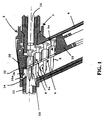
- an explosively actuated tool of which only the front end portion and associated part of a fastener magazine is shown, comprises a body 2 carrying at its forward end a magazine 4 which receives a rectilinear carrier strip 6 carrying a series of fasteners 8 arranged in parallel.
- the carrier strip comprises a series of interconnected carrier segments 6a each of which carries a respective fastener 8, the carrier segment 6a at the leading end of the strip 6 being detached from the remainder of the strip during driving of the associated fastener.
- the magazine 4 includes a spring-actuated pusher member 10 which engages the trailing end of the carrier strip 6 so as to push the leading segment of the carrier strip and the fastener carried thereby into an axially displaceable fastener guide 12 mounted within the forward end of the body 2.
- the fastener guide 12 forms an extension of the barrel (not shown) of the tool.
- the fastener guide 12 and barrel receive a driving piston 16 the forward end of which is shown in the drawings and which, when the tool is fired, drives the fastener within the guide 12 into the substrate. This is a high energy process and the associated segment 6a of the carrier strip within the fastener guide 12 will be destroyed during this process.
- Cocking of the tool to permit firing occurs by pressing the forward end of the fastener guide 12 against the substrate thereby causing the fastener guide 12 to retract relative to the body 2 of the tool.
- the cocking and firing mechanism activated by retraction of the fastener guide or barrel extension is substantially conventional and will be well understood by those skilled in the art; it is therefore unnecessary for a description to be given of that system. What is important however is that the safety system provided by this mechanism is such that the tool cannot be actuated unless the forward end of the fastener guide 12 is pressed against the substrate so that it is held by the substrate in a retracted condition within the forward end of the body 2 and this safety requirement is fundamental in explosively actuated tools of this general type as will be well understood by those skilled in the art.
- the magazine 4 extends obliquely to the longitudinal axis of the tool so that the magazine 4 over most of its length is axially displaced from the front of the tool body 2 and hence, in use, is axially displaced from the substrate.
- a spring-loaded safety latch 20 is mounted on the body 2 opposite the magazine 4.
- the latch 20 has a cam or pad 22 projecting through a slot in the fastener guide 12 into the interior of the fastener guide.
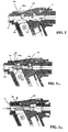
- the latch 20 also has a locking nose 20a which, in its locking position (see Figure 2), abuts against a step 24 formed in the outer surface of the fastener guide 12 with the fastener guide 12 in its extended position relative to the body 2. Accordingly when the latch 20 is in the locking condition it acts to prevent retraction of the fastener guide 12 when pressed against the substrate and hence prevents cocking and subsequent firing of the tool.
- the latch 20 is movable into a released position in which its locking nose 20a is moved out of the step 24 by reaction between the leading end of the carrier segment 6a within the guide 12 and the cam 22 which projects into the guide 12 (see Figures 1, 3a and 3b). More particularly, under the effect of the pressure exerted on the trailing end of the carrier strip 6 by the pusher member 10 within the magazine, the leading end of the carrier strip segment 6a within the fastener guide 12 will push the cam 22 to pivot the latch 20 out of locking engagement with the step 24 in the fastener guide. In this condition the fastener guide 12 is thus capable of retraction into the body 2 when pressed against the substrate to thereby enable actuation of the tool.
- the inner surface of the cam 22 which reacts with the carrier strip segment may lie relatively close to the inner surface of the fastener guide 12 and may therefore be vulnerable to impact by the forward end of the piston 16 as it is driven through the fastener guide by the force of the explosive charge. Impact of the forward end of the piston 16 with the cam 22 would cause serious damage to the tool.
- the inner surface of the latch 20 has a second cam 26 inwardly of the locking nose 20a.
- Displacement of the latch 20 by co-operation with the leading end of the carrier strip segment positions the locking nose 20a out of the step 24 and radially beyond the outer surface of the fastener guide 12 sufficient to permit retraction of the fastener guide 12.
- the second cam 26 interacts with the outer surface of the fastener guide 12 to thereby further pivot the latch 20 outwardly so as to ensure that the main cam 22 is clearly withdrawn from the bore of the fastener guide 12 and is positively held in that withdrawn position by the co-operation between the second cam 26 and the outer surface of the fastener guide 12 when the fastener guide 12 is in its fully retracted position during firing of the tool (see Figure 3b). Accordingly in this mode it is thereby ensured that the main cam 22 cannot interfere with operation of the driving piston.
- a secondary cam for interaction with the latch 20 may be formed on the outer surface of the fastener guide to achieve a similar effect.
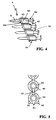
- each segment 6a of the carrier strip 6 consists of a generally cylindrical body 40 through which the fastener 8 projects.
- Diametrically-opposed axial fins 42 project from the cylindrical body 40 and connect to the cylindrical bodies 40 of the following and trailing segments 6a of the carrier strip.
- Each of the axial fins 42 is grooved midway along its length to facilitate a separation of two adjacent segments in that zone when the leading carrier segment is within the fastener guide and the tool is actuated.
- each segment 6a of the carrier strip is formed with an annular flange 44.
- the fastener 8 present within the bore of the fastener guide 12 preparatory to firing is located in the guide by the interaction between the head of the fastener and inner surface of the guide, the interaction between the annular flange 44 of the associated segment 6a of the carrier strip and the inner surface of the guide, and the support provided for that segment of the carrier strip by the remaining segments of the carrier strip within the magazine and to which it is still attached at that point.
- the engagement of the main cam 22 of the pivotal latch 20 takes place initially at the forward end of the carrier segment, namely at the annular flange 44 and the immediately adjacent part of the fin 42 with the point of displacement travelling rearwardly along the fin 42 as the latch 20 is pivoted into its released position by the action of the carrier segment.
- the tool might not necessarily be used immediately, and, during the ensuing period prior to use, the tool may be subject to various types of rough handling, for example the tool may be subject to vibration and shaking on the floor of a vehicle, and unless other measures are taken to maintain correct alignment the carrier segment and associated fastener may displace both rotationally and axially within the fastener guide 12 so that it is no longer in the correct position for co-operation with the cam 22.
- this is achieved by forming at the trailing end of the annular flange 44 of the final segment of the strip a pair of radially-extending lugs 46 one at each side of the fin 42.
- the lugs 46 interact with the surface of the pusher member 10 (see Figure 6) to provide a stable support for the carrier segment so as to prevent rotation thereof.
- the pusher member 10 has on its outer surface a small axial abutment 10a (see Figures 7a and 7b) which is engageable by the rear surface of the annular flange 44 of the segment so as to restrict rearwards axial movement of the segment.
- a limited amount of axial movement is permitted (as may be seen by a comparison of Figures 7a and 7b)
- the extent of the permitted movement is such that the carrier segment is still in an axial position in which it can effectively co-operate with the cam 22 of the pivotal latch 20.
- the guide element 50 has a part-cylindrical inner surface which matches that of the fastener guide 12 and is appropriately slotted (see Figure 8) to permit passage of the forward end of the fastener 8 into the fastener guide 12.
- the rear edge of the guide element 50 also assumes a role during the firing of the tool in that it supports the carrier segment within the fastener guide 12 relative to the remainder of the carrier strip as the fastener is being driven forward by the action of the piston 16 and that carrier segment becomes sheared from the following segments.
- the inner surface of this guide element 50 also performs a guiding function in conjunction with the head of the fastener as it is advanced through the fastener guide into the substrate.
- the final carrier segment can incorporate alternative means which act to stabilise the position of that segment within the fastener guide to ensure correct co-operation with the pivotal latch 20.
- one particular advantage of using the two radially-projecting lugs 46 is that they provide both a visual and tactile indication as to the correct orientation of the carrier strip within the magazine so as to ensure that the strip is inserted with the lugs at the trailing end rather than at the leading end with respect to the magazine. If alternative means are used for ensuring stabilisation of the final carrier segment within the fastener guide, steps may need to be taken to ensure that the correct direction of insertion of the carrier strip into the magazine is immediately discernible to an operator.
- the magazine also includes a cover 60 ( Figures 9 and 10) which can be opened to permit loading of a fresh carrier strip 6 with fasteners 8.
- the cover 60 is closed so that substantial parts of the structure illustrated in Figures 1 to 3 are enclosed and protected within the cover 60.
- the magazine also includes means visible by an operator when the cover 60 is closed to indicate the number of fasteners 8 remaining for use on the carrier strip 6. In this respect, even although the interlock system previously described ensures that the tool cannot be fired when there are no fasteners present, nevertheless for the convenience of the operator it is still desirable to know how many fasteners are remaining within the tool without the necessity of opening the cover 60.
- Figure 9 shows the magazine with the cover 60 in its closed condition in which it encloses the components shown in Figures 1 to 3.
- the cover 60 is mounted for sliding movement along the axis of the magazine between its closed position as shown in Figure 9 in which its upper end is adjacent to the body 2 of the tool and a lower position in which its upper end has moved downwardly along the magazine to facilitate loading of the magazine with a fresh carrier strip.
- the cover 60 includes a series of apertures 62 regularly spaced along the axis of the magazine. An appropriately coloured part 10b of the pusher member 10 is visible through respective ones of these apertures 62 as the pusher member 10 advances upwardly through the magazine as the fasteners are sequentially fired.
- the apertures are appropriately numbered so that an operator, by observing in which numbered apertures 62 is visible the coloured part 10b of the pusher member, will readily ascertain the number of fasteners remaining within the tool.
Landscapes
- Engineering & Computer Science (AREA)
- Mechanical Engineering (AREA)
- Chemical & Material Sciences (AREA)
- Combustion & Propulsion (AREA)
- Portable Nailing Machines And Staplers (AREA)
Applications Claiming Priority (4)
| Application Number | Priority Date | Filing Date | Title |
|---|---|---|---|
| AUPP602898 | 1998-09-18 | ||
| AUPP6028A AUPP602898A0 (en) | 1998-09-18 | 1998-09-18 | Power actuated tools with magazine feed |
| AUPP7252A AUPP725298A0 (en) | 1998-11-23 | 1998-11-23 | Power actuated tools with magazine feed |
| AUPP725298 | 1998-11-23 |
Publications (2)
| Publication Number | Publication Date |
|---|---|
| EP0987086A2 true EP0987086A2 (de) | 2000-03-22 |
| EP0987086A3 EP0987086A3 (de) | 2000-12-20 |
Family
ID=25645876
Family Applications (1)
| Application Number | Title | Priority Date | Filing Date |
|---|---|---|---|
| EP99307206A Withdrawn EP0987086A3 (de) | 1998-09-18 | 1999-09-13 | Kraftgetriebene Werkzeuge mit Magazinzuführung |
Country Status (2)
| Country | Link |
|---|---|
| US (1) | US6267284B1 (de) |
| EP (1) | EP0987086A3 (de) |
Cited By (12)
| Publication number | Priority date | Publication date | Assignee | Title |
|---|---|---|---|---|
| EP1277549A1 (de) | 2001-07-20 | 2003-01-22 | Adolf Würth GmbH & Co. KG | Anordnung zum Zuführen von Bolzen zu einem Bolzenschubgerät |
| EP1193405A3 (de) * | 2000-09-29 | 2004-01-14 | Illinois Tool Works Inc. | Verbindungsstreifen und Streifen mit damit verbundenen Befestigungselementen |
| EP1283091A3 (de) * | 2001-08-10 | 2004-04-14 | Illinois Tool Works Inc. | Teleskopisches Stabilisierungselement für ein Setzgerät |
| EP1500472A1 (de) * | 2003-07-23 | 2005-01-26 | Societe De Prospection Et D'inventions Techniques Spit | Eintreibwerkzeug für Befestigungsmittel mit Sicherheitsklinke |
| FR2865427A1 (fr) * | 2004-01-23 | 2005-07-29 | Prospection & Inventions | Appareil a tir indirect de scellement d'elements de fixation dans un materiau support |
| CN1323808C (zh) * | 2005-06-08 | 2007-07-04 | 黄修文 | 可射各种规格射钉的多功能射钉器 |
| EP1391268A3 (de) * | 2002-08-19 | 2008-11-12 | Illinois Tool Works Inc. | Werkzeug für Befestigungsmittel mit Magazin-Schlepphebel |
| WO2008125311A3 (de) * | 2007-04-14 | 2008-12-11 | Boellhoff Verbindungstechnik | Setzgerät, verfahren und vorrichtungen zum zuführen von befestigungselementen |
| EP2592286A1 (de) * | 2011-11-08 | 2013-05-15 | Hip Innovations, LLC | Anker und Ankersysteme zum Aufhängen von Objekten sowie Werkzeug zum Anbringen solcher Anker |
| WO2019120827A1 (de) * | 2017-12-20 | 2019-06-27 | Hilti Aktiengesellschaft | Befestigungselementestreifen |
| US10814465B2 (en) | 2016-03-22 | 2020-10-27 | Stanley Black & Decker, Inc. | Safety device for tackers |
| CN112276865A (zh) * | 2020-10-19 | 2021-01-29 | 南京腾亚精工科技股份有限公司 | 一种轴向射钉枪击发器 |
Families Citing this family (42)
| Publication number | Priority date | Publication date | Assignee | Title |
|---|---|---|---|---|
| DE19950349B4 (de) * | 1999-10-19 | 2006-07-27 | Hilti Ag | Setzgerät für Befestigungselemente |
| US6651862B2 (en) * | 2001-04-30 | 2003-11-25 | Illinois Tool Works Inc. | Trim-type fastener driving tool |
| KR200250504Y1 (ko) * | 2001-05-11 | 2001-10-19 | 송석주 | 공기압력총못량표시기 |
| USD472123S1 (en) | 2001-10-04 | 2003-03-25 | Yung Chen Juan | Collars for a row of nails |
| DE20119463U1 (de) * | 2001-11-29 | 2002-01-24 | Hilti Ag, Schaan | Tragbares, brennkraftbetriebenes Setzgerät für Befestigungselemente |
| US20030121948A1 (en) * | 2001-12-31 | 2003-07-03 | Hsien Chen Ming | Device for disabling shooting when nails runs out in a pneumatic nailer |
| US6796476B2 (en) * | 2002-09-11 | 2004-09-28 | Illinois Tool Works Inc. | Power control system for a framing tool |
| US7021511B2 (en) | 2002-09-18 | 2006-04-04 | Illinois Tool Works Inc. | Lock-out mechanism for powder actuated tool |
| FR2850895B1 (fr) * | 2003-02-10 | 2006-03-03 | Prospection & Inventions | Bande d'elements de fixation pour appareil de scellement avec chargeur destine a recevoir la bande, l'appareil et le chargeur |
| DE10351419B4 (de) * | 2003-11-04 | 2006-04-27 | Hilti Ag | Setzgerät |
| DE10354725B4 (de) * | 2003-11-22 | 2015-02-19 | Hilti Aktiengesellschaft | Mündungsteil für Setzgeräte und Setzgerät |
| USD514414S1 (en) * | 2003-12-19 | 2006-02-07 | Teng Tino S | Strip of collated fasteners for fastener-driving tool |
| US20060108391A1 (en) * | 2003-12-31 | 2006-05-25 | Leasure Jeremy D | Pneumatic fastener |
| US6913179B1 (en) * | 2004-01-21 | 2005-07-05 | Nailermate Enterprise Corporation | Safety device for locking the safety bar of pneumatic nailers |
| US6908021B1 (en) * | 2004-02-04 | 2005-06-21 | Nailermate Enterprise Corp. | Safety catch mechanism of nail guns |
| US20050224555A1 (en) * | 2004-04-02 | 2005-10-13 | Acco Brands, Inc. | Stapler with inside leg support |
| CN101052497B (zh) * | 2004-07-23 | 2010-10-06 | 阿科布兰兹美国有限责任公司 | 用于钉书机的少钉指示器 |
| USD514904S1 (en) | 2004-09-09 | 2006-02-14 | Acco Brands, Inc. | Stapler |
| JP2006123064A (ja) * | 2004-10-28 | 2006-05-18 | Max Co Ltd | 釘打機のマガジンにおける釘ガイド機構 |
| US6966477B1 (en) * | 2004-11-15 | 2005-11-22 | Basso Industry Corp | Safety device for preventing a nailer from dry firing |
| CN100374249C (zh) * | 2005-01-07 | 2008-03-12 | 力肯实业股份有限公司 | 打钉枪空钉制动装置 |
| US7328826B2 (en) * | 2005-03-28 | 2008-02-12 | Illinois Tool Works Inc. | Power nailer with driver blade blocking mechanism magazine |
| KR200389873Y1 (ko) * | 2005-04-20 | 2005-07-18 | 제일타카 주식회사 | 타카장치의 네일 낙하방지부재 |
| US7540400B2 (en) | 2006-01-06 | 2009-06-02 | Staples The Office Superstore, Llc | Stapler having a moveable strike plate with lockout mechanism |
| US7395955B2 (en) | 2006-01-06 | 2008-07-08 | Staples The Office Superstore, Llc | Stapler |
| DE102006000254A1 (de) * | 2006-05-30 | 2007-12-06 | Hilti Ag | Handgeführtes Setzgerät |
| US20080041915A1 (en) * | 2006-08-16 | 2008-02-21 | James Morris Boyer | Nail gun reload indicator |
| DE102006035459A1 (de) * | 2006-11-27 | 2008-05-29 | Hilti Ag | Handgeführtes Eintreibgerät |
| US7802710B1 (en) * | 2008-09-29 | 2010-09-28 | Yeun Chang Hardware Tool Co., Ltd. | Nail pusher that can push nails successively |
| DE102008054483A1 (de) * | 2008-12-10 | 2010-06-17 | Hilti Aktiengesellschaft | Freischaltadapter für Einzelsetzungen mit handgeführten Setzgeräten |
| US8746526B2 (en) * | 2009-09-15 | 2014-06-10 | Robert Bosch Gmbh | Fastener driver with blank fire lockout |
| US8336748B2 (en) * | 2009-09-15 | 2012-12-25 | Robert Bosch Gmbh | Fastener driver with driver assembly blocking member |
| JP5701658B2 (ja) * | 2011-03-31 | 2015-04-15 | 株式会社マキタ | 打ち込み工具 |
| US20130193182A1 (en) * | 2012-02-01 | 2013-08-01 | Samson Power Tool Co., Ltd. | Nail guiding device for coil nailer |
| US10814464B2 (en) * | 2015-10-16 | 2020-10-27 | Brian Keith Orchard | Deck clip magazine |
| US11110577B2 (en) | 2017-11-16 | 2021-09-07 | Milwaukee Electric Tool Corporation | Pneumatic fastener driver |
| WO2019241225A1 (en) | 2018-06-11 | 2019-12-19 | Milwaukee Electric Tool Corporation | Gas spring-powered fastener driver |
| US12427634B2 (en) | 2018-06-11 | 2025-09-30 | Milwaukee Electric Tool Corporation | Gas spring-powered fastener driver |
| CN115397621A (zh) | 2020-03-27 | 2022-11-25 | 米沃奇电动工具公司 | 动力式紧固件驱动器 |
| US12246421B2 (en) | 2020-03-27 | 2025-03-11 | Milwaukee Electric Tool Corporation | Powered fastener driver |
| WO2021202723A1 (en) | 2020-03-31 | 2021-10-07 | Milwaukee Electric Tool Corporation | Powered fastener driver |
| WO2021236940A1 (en) | 2020-05-22 | 2021-11-25 | Milwaukee Electric Tool Corporation | Dry-fire lockout and last fastener retention mechanism for powered fastener driver |
Family Cites Families (17)
| Publication number | Priority date | Publication date | Assignee | Title |
|---|---|---|---|---|
| US3606128A (en) * | 1967-03-07 | 1971-09-20 | Reich Maschf Gmbh Karl | Percussion machine for fasteners |
| US3670942A (en) * | 1970-10-15 | 1972-06-20 | Omark Industries Inc | Automatic feeding of fasteners |
| US3797723A (en) * | 1972-02-07 | 1974-03-19 | Spotnails | Fastener-driving tool |
| US3961408A (en) * | 1975-05-05 | 1976-06-08 | Multifastener Corporation | Fastener installation head |
| US4732309A (en) * | 1984-08-10 | 1988-03-22 | Black & Decker, Inc. | Staple magazine |
| DE3608146A1 (de) * | 1986-03-12 | 1987-09-17 | Hilti Ag | Pulverkraftbetriebenes setzgeraet |
| US4715522A (en) * | 1986-12-05 | 1987-12-29 | Jordan Rodney B | Nail reserve indicator |
| DE3806625A1 (de) * | 1988-03-02 | 1989-09-14 | Hilti Ag | Pulverkraftbetriebenes setzgeraet |
| DE3806626C2 (de) * | 1988-03-02 | 1997-04-24 | Hilti Ag | Pulverkraftbetriebenes Setzgerät |
| DE4032200C2 (de) * | 1990-10-11 | 2000-01-20 | Hilti Ag | Setzgerät für Befestigungselemente |
| JP2640988B2 (ja) * | 1990-11-30 | 1997-08-13 | 株式会社 マキタ | 釘打機における釘の空打防止装置 |
| DE4122873A1 (de) * | 1991-07-11 | 1993-01-14 | Hilti Ag | Pulverkraftbetriebenes setzgeraet mit magazin fuer befestigungselemente |
| AU667162B2 (en) * | 1993-05-13 | 1996-03-07 | Stanley-Bostitch, Inc. | Fastener driving device particularly suited for use as a roofing nailer |
| FR2730443B1 (fr) * | 1995-02-15 | 1997-04-11 | Spit Soc Prospect Inv Techn | Appareil de scellement a piston propulse par gaz comprime |
| DE19517230A1 (de) * | 1995-05-15 | 1996-11-21 | Hilti Ag | Pulverkraftbetriebenes Setzgerät mit Magazin für Befestigungselemente |
| DE19642295A1 (de) * | 1996-10-14 | 1998-04-16 | Hilti Ag | Pulverkraftbetriebenes Setzgerät mit Magazin für Befestigungselemente |
| US6036072A (en) * | 1998-10-27 | 2000-03-14 | De Poan Pneumatic Corporation | Nailer magazine |
-
1999
- 1999-09-13 EP EP99307206A patent/EP0987086A3/de not_active Withdrawn
- 1999-09-17 US US09/397,470 patent/US6267284B1/en not_active Expired - Fee Related
Cited By (25)
| Publication number | Priority date | Publication date | Assignee | Title |
|---|---|---|---|---|
| EP1193405A3 (de) * | 2000-09-29 | 2004-01-14 | Illinois Tool Works Inc. | Verbindungsstreifen und Streifen mit damit verbundenen Befestigungselementen |
| EP1277549A1 (de) | 2001-07-20 | 2003-01-22 | Adolf Würth GmbH & Co. KG | Anordnung zum Zuführen von Bolzen zu einem Bolzenschubgerät |
| EP1283091A3 (de) * | 2001-08-10 | 2004-04-14 | Illinois Tool Works Inc. | Teleskopisches Stabilisierungselement für ein Setzgerät |
| AU2002300051B2 (en) * | 2001-08-10 | 2004-06-17 | Illinois Tool Works Inc. | Telescoping support device for fastener driving tool |
| KR100882524B1 (ko) * | 2001-08-10 | 2009-02-06 | 일리노이즈 툴 워크스 인코포레이티드 | 지지디바이스 및 패스너 발사용 공구 |
| EP1391268A3 (de) * | 2002-08-19 | 2008-11-12 | Illinois Tool Works Inc. | Werkzeug für Befestigungsmittel mit Magazin-Schlepphebel |
| EP1500472A1 (de) * | 2003-07-23 | 2005-01-26 | Societe De Prospection Et D'inventions Techniques Spit | Eintreibwerkzeug für Befestigungsmittel mit Sicherheitsklinke |
| FR2857896A1 (fr) * | 2003-07-23 | 2005-01-28 | Prospection & Inventions | Appareil d'entrainement d'elements de fixation a sabot de securite |
| US7059507B2 (en) | 2003-07-23 | 2006-06-13 | Societe De Prospection Et D'inventions Techniques Spit | Apparatus for driving fasteners, with safety shoe |
| FR2865427A1 (fr) * | 2004-01-23 | 2005-07-29 | Prospection & Inventions | Appareil a tir indirect de scellement d'elements de fixation dans un materiau support |
| US8016174B2 (en) | 2004-01-23 | 2011-09-13 | Societe De Prospection Et D'inventions Techniques Spit | Indirect fire device for fixing fasteners in a substrate material |
| AU2005205983B2 (en) * | 2004-01-23 | 2008-06-12 | Societe De Prospection Et D'inventions Techniques Spit | Indirect fire device for fixing fasteners in a substrate material |
| JP2007518583A (ja) * | 2004-01-23 | 2007-07-12 | ソシエテ ドゥ プロスペクティオン エ ディンベンティオン テクニク スピ | 支持材料にファスナを固定するための間接発射装置 |
| WO2005070623A1 (en) * | 2004-01-23 | 2005-08-04 | Societe De Prospection Et D'inventions Techniques Spit | Indirect fire device for fixing fasteners in a substrate material |
| CN1323808C (zh) * | 2005-06-08 | 2007-07-04 | 黄修文 | 可射各种规格射钉的多功能射钉器 |
| US8141761B2 (en) | 2007-04-14 | 2012-03-27 | Bollhoff Verbindungstechnik Gmbh | Setting device, method and apparatuses for feeding fastening elements |
| WO2008125311A3 (de) * | 2007-04-14 | 2008-12-11 | Boellhoff Verbindungstechnik | Setzgerät, verfahren und vorrichtungen zum zuführen von befestigungselementen |
| EP2592286A1 (de) * | 2011-11-08 | 2013-05-15 | Hip Innovations, LLC | Anker und Ankersysteme zum Aufhängen von Objekten sowie Werkzeug zum Anbringen solcher Anker |
| US10814465B2 (en) | 2016-03-22 | 2020-10-27 | Stanley Black & Decker, Inc. | Safety device for tackers |
| US11633839B2 (en) | 2016-03-22 | 2023-04-25 | Stanley Black & Decker, Inc. | Safety device for tackers |
| WO2019120827A1 (de) * | 2017-12-20 | 2019-06-27 | Hilti Aktiengesellschaft | Befestigungselementestreifen |
| US11746814B2 (en) | 2017-12-20 | 2023-09-05 | Hilti Aktiengesellschaft | Strip of fastening elements |
| AU2018389897B2 (en) * | 2017-12-20 | 2024-09-05 | Hilti Aktiengesellschaft | Strip of fastening elements |
| CN112276865A (zh) * | 2020-10-19 | 2021-01-29 | 南京腾亚精工科技股份有限公司 | 一种轴向射钉枪击发器 |
| CN112276865B (zh) * | 2020-10-19 | 2024-06-04 | 南京腾亚精工科技股份有限公司 | 一种轴向射钉枪击发器 |
Also Published As
| Publication number | Publication date |
|---|---|
| EP0987086A3 (de) | 2000-12-20 |
| US6267284B1 (en) | 2001-07-31 |
Similar Documents
| Publication | Publication Date | Title |
|---|---|---|
| US6267284B1 (en) | Power actuated tools with magazine feed | |
| KR101053476B1 (ko) | 화약 작동 공구의 잠금 메카니즘 | |
| US4804127A (en) | Fastener driving gun | |
| US7059507B2 (en) | Apparatus for driving fasteners, with safety shoe | |
| US7000294B2 (en) | Fastener driving tools | |
| AU615049B2 (en) | Powder-actuated fastener driving tool | |
| JPS62218078A (ja) | 鋲打機 | |
| US6851262B1 (en) | Tools for securing connectors using explosive charges and methods for using the same | |
| US4114792A (en) | Powder actuated tool | |
| IE41492B1 (en) | Explosive-powered fastener-driving tool | |
| US3330108A (en) | Explosively actuated tool | |
| JPS5949878B2 (ja) | 爆発動力緊締具打込工具 | |
| US5811717A (en) | Powder-actuated tool cartridge clip with position indicator mark | |
| KR101020524B1 (ko) | 고정시키는 부재를 갖춘 매거진 조립체 | |
| AU754213B2 (en) | Power actuated tools with magazine feed | |
| JPS5942280A (ja) | フアスナ打込み工具 | |
| US4364506A (en) | Fastener driving tool with cartridge ejector | |
| US3871321A (en) | Self-cocking explosively actuated cable cutter | |
| WO1989000483A1 (en) | Fastener setting tools | |
| US6880738B2 (en) | Propellant charge magazine for a setting tool | |
| CA1291845C (en) | Arrangement in nail driving apparatus | |
| JP4877463B2 (ja) | ファスナー打ち込み工具のファスナー送り機構 | |
| EP1654788B1 (de) | Werkzeuge zur sicherung von verbindern durch verwendung von explosionsladungen und verfahren zur verwendung dafür |
Legal Events
| Date | Code | Title | Description |
|---|---|---|---|
| PUAI | Public reference made under article 153(3) epc to a published international application that has entered the european phase |
Free format text: ORIGINAL CODE: 0009012 |
|
| AK | Designated contracting states |
Kind code of ref document: A2 Designated state(s): AT BE CH DE DK ES FI FR GB GR IE IT LI NL PT SE |
|
| AX | Request for extension of the european patent |
Free format text: AL;LT;LV;MK;RO;SI |
|
| PUAL | Search report despatched |
Free format text: ORIGINAL CODE: 0009013 |
|
| AK | Designated contracting states |
Kind code of ref document: A3 Designated state(s): AT BE CH CY DE DK ES FI FR GB GR IE IT LI LU MC NL PT SE |
|
| AX | Request for extension of the european patent |
Free format text: AL;LT;LV;MK;RO;SI |
|
| RIC1 | Information provided on ipc code assigned before grant |
Free format text: 7B 25C 1/00 A, 7B 25C 1/18 B, 7B 25C 5/16 B |
|
| 17P | Request for examination filed |
Effective date: 20010426 |
|
| AKX | Designation fees paid |
Free format text: AT BE CH DE DK ES FI FR GB GR IE IT LI NL PT SE |
|
| 17Q | First examination report despatched |
Effective date: 20030613 |
|
| 18D | Application deemed to be withdrawn |
Effective date: 20031024 |
|
| D18D | Application deemed to be withdrawn (deleted) | ||
| RAP1 | Party data changed (applicant data changed or rights of an application transferred) |
Owner name: CETRAM PTY LIMITED |
|
| RAP1 | Party data changed (applicant data changed or rights of an application transferred) |
Owner name: CETRAM PTY LIMITED |
|
| STAA | Information on the status of an ep patent application or granted ep patent |
Free format text: STATUS: THE APPLICATION HAS BEEN WITHDRAWN |
|
| 18W | Application withdrawn |
Effective date: 20051024 |