EP0987364A2 - Dichtungseinrichtung und Verfahren zur Abdichtung von Druckzonen in einer Papiermaschine - Google Patents
Dichtungseinrichtung und Verfahren zur Abdichtung von Druckzonen in einer Papiermaschine Download PDFInfo
- Publication number
- EP0987364A2 EP0987364A2 EP99111864A EP99111864A EP0987364A2 EP 0987364 A2 EP0987364 A2 EP 0987364A2 EP 99111864 A EP99111864 A EP 99111864A EP 99111864 A EP99111864 A EP 99111864A EP 0987364 A2 EP0987364 A2 EP 0987364A2
- Authority
- EP
- European Patent Office
- Prior art keywords
- sealing
- holder
- sealing device
- sealing element
- stop
- Prior art date
- Legal status (The legal status is an assumption and is not a legal conclusion. Google has not performed a legal analysis and makes no representation as to the accuracy of the status listed.)
- Granted
Links
Images
Classifications
-
- D—TEXTILES; PAPER
- D21—PAPER-MAKING; PRODUCTION OF CELLULOSE
- D21F—PAPER-MAKING MACHINES; METHODS OF PRODUCING PAPER THEREON
- D21F3/00—Press section of machines for making continuous webs of paper
- D21F3/02—Wet presses
- D21F3/10—Suction rolls, e.g. couch rolls
Definitions
- the invention relates to a sealing device for lateral sealing at least one overpressure or adjacent to a moving surface Vacuum zone in a paper machine with at least one at least movable in areas in a receiving area of a holder Arranged sealing element that with to apply to the moving surface a contact pressure can be applied.
- the invention enables the contact pressure with which the Sealing element is applied during operation, i.e. at the moving one Surface applied sealing element, to maintain and thus for to provide a resilient mounting of the sealing element. In this way vibrations of the moving surface can be absorbed, which at relative to the immovable sealing element for increased wear of the sealing element would lead.
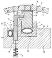
- the stop element 70 engages behind a radially inner boundary surface the undercut with respect to the radial direction representing groove 16, this boundary surface as a radially inner, stop surface 16a interacting with the stop element 70 serves.
- the facing the jacket 20, in the state according to the figure boundary surface of the groove 16 spaced from the engagement section 75 forms a radially outer stop surface 16b of the sealing element 15 for the stop element 70.
- the return element 35 could - for example, with a correspondingly modified arrangement be designed as a tension spring.
- the contact pressure hose 55 pressurized. That then relative to the Holder 10 on the jacket 20 to move sealing element 15 takes with its radially inner stop surface 16a on the stop element 70 the engagement portion 75 against the restoring force of the return element 35 with.
- the from the clamping member 30, d. H. from the pressure hose 50 over the Piston 60 clamping force exerted on stop element 70 is such dimensioned that the sealing element 15 even with an increase in the the contact pressure applied 55 no more pressure the jacket 20 can be moved.
- the fluid pressure within the pressure hose 55 can then to the clamping fixation of the stop element 70 also by one certain amount be reduced in such a way that still ensures is that the sealing element 15 without play between the pressure hose 55 and the stop element 70 is held to its sealing function to fulfill.
- the sealing element 15 is in any case due to the pressure standing pressure hose 55 resiliently mounted. Movements that are transferred to the sealing element 15 via the jacket 20 thus caught by the sealing device according to the invention, whereby the wear of the sealing element 15, d. H. the wear of the Wear layer 15a is minimized.
Landscapes
- Sealing Devices (AREA)
- Paper (AREA)
- Package Closures (AREA)
Abstract
Description
- 10
- Halter
- 11
- Seitenwand
- 15
- Dichtelement
- 15a
- Verschleißabschnitt, Verschleißschicht
- 16
- Hinterschneidung, Nut
- 16a, 16b
- Anschlagflächen
- 17
- Aufnahmebereich, Aufnahmekanal
- 20
- Bewegte Fläche, Mantel
- 21
- Bohrungen
- 30
- Klemmorgan
- 35
- Rückholelement
- 45
- Nut
- 50
- Klemmdruckschlauch
- 55
- Anpreßdruckschlauch
- 60
- Kolben
- 70
- Anschlagelement
- 72
- Abschnitt des Anschlagelementes
- 75
- Eingriffsabschnitt des Anschlagelementes
- 80
- Träger
- 82
- Auflagefläche
- 83
- Vertiefung für den Halter
- 85
- Vertiefung für das Anschlagelement
- P1, P2
- Druckzonen
Claims (14)
- Dichtungseinrichtung zur seitlichen Abdichtung wenigstens einer an eine bewegte Fläche (20) angrenzenden Überdruck- oder Unterdruckzone (P1, P2) in einer Papiermaschine mit wenigstens einem zumindest bereichsweise in einem Aufnahmebereich (17) eines Halters (10) beweglich angeordneten Dichtelement (15), das zum Anlegen an die bewegte Fläche (20) mit einer Anpreßkraft beaufschlagbar ist,
dadurch gekennzeichnet,
daß ein in einem jeweiligen Abstand zur bewegten Fläche (20) fixierbares und die Anlegebewegung des Dichtelementes (15) begrenzendes Anschlagelement (70) vorgesehen ist. - Dichtungseinrichtung nach Anspruch 1,
dadurch gekennzeichnet,
daß das angelegte Dichtelement (15) gegen die Anpreßkraft relativ zum Anschlagelement (70) und zum Halter (10) bewegbar ist. - Dichtungseinrichtung nach Anspruch 1 oder 2,
dadurch gekennzeichnet,
daß das Anschlagelement (70) mit einem Eingriffsabschnitt (75) in eine Hinterschneidung (16), insbesondere in eine Nut, des Dichtelementes (15) eingreift, wobei das Dichtelement (15) relativ zum Eingriffsabschnitt (75) zwischen zwei die Hinterschneidung (16) begrenzenden Anschlagflächen (16a, 16b) bewegbar ist. - Dichtungseinrichtung nach zumindest einem der Ansprüche 1 bis 3,
dadurch gekennzeichnet,
daß das Anschlagelement (70) zur Fixierung fest mit dem Halter (10) koppelbar ist. - Dichtungseinrichtung nach zumindest einem der Ansprüche 1 bis 4,
dadurch gekennzeichnet,
daß das Anschlagelement (70) zur Fixierung an den Halter (10) anpreßbar, insbesondere zwischen dem Halter (10) und einem Klemmorgan (30) einklemmbar ist. - Dichtungseinrichtung nach Anspruch 5,
dadurch gekennzeichnet,
daß als Klemmorgan (30) ein Klemmdruckschlauch (50) vorgesehen ist, der bevorzugt zwischen dem Dichtelement (15) und einem Träger (80) für den Halter (10) in einer im Träger (80) ausgebildeten Nut (45) angeordnet ist. - Dichtungseinrichtung nach Anspruch 6,
dadurch gekennzeichnet,
daß zwischen dem Klemmdruckschlauch (50) und dem Anschlagelement (70) ein in der Nut (45) beweglicher Kolben (60) angeordnet ist. - Dichtungseinrichtung nach zumindest einem der vorhergehenden Ansprüche,
dadurch gekennzeichnet,
daß das Anschlagelement (70) gegen eine Rückstellkraft relativ zum Halter (10) bewegbar, insbesondere durch das mit der Anpreßkraft beaufschlagte Dichtelement (15), bevorzugt über eine Anschlagfläche (16a) des Dichtelementes (15), mitnehmbar ausgebildet ist. - Dichtungseinrichtung nach zumindest einem der vorhergehenden Ansprüche,
dadurch gekennzeichnet,
daß das Anschlagelement (70) über ein elastisch verformbares Rückholelement (35), insbesondere über eine Zug- oder Druckfeder, mit dem Halter (10), bevorzugt mit einem Träger (80) für den Halter (10) gekoppelt ist. - Dichtungseinrichtung nach zumindest einem der vorhergehenden Ansprüche,
dadurch gekennzeichnet,
daß das Dichtelement (15) mittels wenigstens eines Anpreßdruckschlauches (55), der insbesondere zwischen dem Dichtelement (15) und einer von der bewegten Fläche (20) abgewandten Begrenzungsfläche des Aufnahmebereiches (17) angeordnet ist, an die bewegte Fläche (20) anlegbar ist. - Dichtungseinrichtung nach zumindest einem der vorhergehenden Ansprüche,
dadurch gekennzeichnet,
daß das Dichtelement (15) mit einem mit der bewegten Fläche (20) zusammenwirkenden, insbesondere in Form einer Schicht vorgesehenen Verschleißabschnitt (15a) versehen ist, dessen Material sich von dem des übrigen Dichtelementes (15) unterscheidet. - Dichtungseinrichtung nach zumindest einem der vorhergehenden Ansprüche zur seitlichen Abdichtung wenigstens einer an die Innen- oder Außenwand eines rotierenden Mantels (20) einer Saug- oder Blaswalze oder eines bewegten Bandes angrenzenden Druckzone (P1, P2).
- Dichtungseinrichtung nach zumindest einem der vorhergehenden Ansprüche zur Verwendung zwischen einem Saug- oder Blaskasten und dem rotierenden Mantel (20) einer Saug- oder Blaswalze oder einem bewegten Band.
- Dichtungseinrichtung nach zumindest einem der vorhergehenden Ansprüche,
dadurch gekennzeichnet,
daß das Dichtelement (15) als eine sich zumindest im wesentlichen über die gesamte Walzenlänge erstreckende Dichtleiste ausgebildet ist.
Applications Claiming Priority (2)
| Application Number | Priority Date | Filing Date | Title |
|---|---|---|---|
| DE19842837 | 1998-09-18 | ||
| DE19842837A DE19842837A1 (de) | 1998-09-18 | 1998-09-18 | Dichtungseinrichtung und Verfahren zur Abdichtung von Druckzonen in einer Papiermaschine |
Publications (3)
| Publication Number | Publication Date |
|---|---|
| EP0987364A2 true EP0987364A2 (de) | 2000-03-22 |
| EP0987364A3 EP0987364A3 (de) | 2000-07-19 |
| EP0987364B1 EP0987364B1 (de) | 2004-03-17 |
Family
ID=7881429
Family Applications (1)
| Application Number | Title | Priority Date | Filing Date |
|---|---|---|---|
| EP99111864A Expired - Lifetime EP0987364B1 (de) | 1998-09-18 | 1999-06-21 | Dichtungseinrichtung zur Abdichtung von Druckzonen in einer Papiermaschine |
Country Status (3)
| Country | Link |
|---|---|
| US (1) | US6312564B1 (de) |
| EP (1) | EP0987364B1 (de) |
| DE (2) | DE19842837A1 (de) |
Cited By (1)
| Publication number | Priority date | Publication date | Assignee | Title |
|---|---|---|---|---|
| EP1496153A1 (de) * | 2003-07-11 | 2005-01-12 | Voith Paper Patent GmbH | Saug- oder Blasvorrichtung mit Dichtungseinrichtung |
Families Citing this family (8)
| Publication number | Priority date | Publication date | Assignee | Title |
|---|---|---|---|---|
| DE10214132A1 (de) * | 2002-03-28 | 2003-10-09 | Voith Paper Patent Gmbh | Dichtungseinrichtung |
| DE10252458A1 (de) * | 2002-11-12 | 2004-06-09 | Voith Paper Patent Gmbh | Dichtungseinrichtung für eine Papiermaschine |
| DE10325686A1 (de) * | 2003-06-06 | 2004-12-23 | Voith Paper Patent Gmbh | Saug- oder Blaseinrichtung in einer Papiermaschine |
| DE10328202A1 (de) * | 2003-06-24 | 2005-01-13 | Voith Paper Patent Gmbh | Pressenpartie |
| SE528727C2 (sv) * | 2005-06-03 | 2007-02-06 | Metso Paper Inc | Anordning för behandling av cellulosamassa i en tvättapparat anordnad med medel för att avlägsna tätningar |
| FI20055371A0 (fi) * | 2005-07-01 | 2005-07-01 | Metso Paper Inc | Listaväline materiaalirainakonetta varten |
| EP2885457B1 (de) * | 2012-08-15 | 2016-07-27 | Voith Patent GmbH | Walze und verfahren zur herstellung und/oder verarbeitung einer papier-, karton- oder tissuebahn |
| CN105392941B (zh) * | 2013-07-19 | 2017-08-22 | 福伊特专利有限公司 | 由多种材质构成的用于造纸机、造纸板机或造棉纸机的密封条 |
Family Cites Families (6)
| Publication number | Priority date | Publication date | Assignee | Title |
|---|---|---|---|---|
| DE542982C (de) * | 1930-06-18 | 1932-02-06 | Downingtown Mfg Company | Saugwalze |
| US2969837A (en) * | 1958-06-10 | 1961-01-31 | Layton Greenfield Inc | Suction roll construction |
| US3802961A (en) * | 1972-07-25 | 1974-04-09 | Diamond Int Corp | Seal construction for pressure or vacuum chambers |
| US4714523A (en) * | 1986-12-18 | 1987-12-22 | Sawyer Jr William D | Suction roll seal strips with teflon insert |
| FI100897B (fi) * | 1993-11-05 | 1998-03-13 | Valmet Paper Machinery Inc | Paperikoneen imutelan imulaatikon tiivistysrakenne ja menetelmä imutel an tiivistekäytössä |
| FI99035C (fi) * | 1995-11-03 | 1997-09-25 | Valmet Corp | Paperikoneen imutelan tiivisterakenne |
-
1998
- 1998-09-18 DE DE19842837A patent/DE19842837A1/de not_active Withdrawn
-
1999
- 1999-06-21 EP EP99111864A patent/EP0987364B1/de not_active Expired - Lifetime
- 1999-06-21 DE DE59908859T patent/DE59908859D1/de not_active Expired - Fee Related
- 1999-09-17 US US09/398,140 patent/US6312564B1/en not_active Expired - Fee Related
Cited By (1)
| Publication number | Priority date | Publication date | Assignee | Title |
|---|---|---|---|---|
| EP1496153A1 (de) * | 2003-07-11 | 2005-01-12 | Voith Paper Patent GmbH | Saug- oder Blasvorrichtung mit Dichtungseinrichtung |
Also Published As
| Publication number | Publication date |
|---|---|
| EP0987364A3 (de) | 2000-07-19 |
| DE19842837A1 (de) | 2000-03-23 |
| US6312564B1 (en) | 2001-11-06 |
| EP0987364B1 (de) | 2004-03-17 |
| DE59908859D1 (de) | 2004-04-22 |
Similar Documents
| Publication | Publication Date | Title |
|---|---|---|
| DE3419999C2 (de) | Rohrverschraubung mit Berührungsdichtung | |
| EP2831452B1 (de) | Scheibenbremse | |
| DE60201409T2 (de) | Absperrventil mit verzögerter zurückziehung der gegenplatte | |
| DE2629654A1 (de) | Manschettendichtung und damit versehene fuehrungs-baugruppe | |
| DE102016111324A1 (de) | Spannvorrichtung | |
| DE102010060767A1 (de) | Verfahren und Anordnung zum Verschweißen von elektrischen Leitern | |
| EP0626524B1 (de) | Druckluftbetätigte Schiebesattel-Scheibenbremse für Nutzfahrzeuge | |
| EP0987364B1 (de) | Dichtungseinrichtung zur Abdichtung von Druckzonen in einer Papiermaschine | |
| EP0943729B1 (de) | Dichtungseinrichtung | |
| EP1709342B1 (de) | Scheibenbremse, insbesondere für ein nutzfahrzeug | |
| DE19882739B4 (de) | Abdichtungsaufbau und Abdichtung für einen Saugkasten in einer Saugwalze in einer Papier-/Kartonmaschine | |
| DE102013011469A1 (de) | Führungseinrichtung für eine Schwimmsattel-Scheibenbremse | |
| EP1239076B1 (de) | Dichtungseinrichtung | |
| DE69711185T2 (de) | Saugkasten für eine papiermaschine und zugehöriges verfahren | |
| DE19842838A1 (de) | Dichtungseinrichtung und Verfahren zur Abdichtung von Druckzonen in einer Papiermaschine | |
| DE2834100A1 (de) | Schwimmsattel-scheibenbremse | |
| EP4474103B1 (de) | Klemm- und/oder bremsvorrichtung für feuchte umgebungen | |
| DE2427768A1 (de) | Einrichtung zum schrittweisen vorschieben von band- oder streifenmaterial, an pressen, stanzen oder dergleichen arbeitsmaschinen | |
| DE102006018088B4 (de) | Führungsmechanismus für Zylindervorrichtung | |
| DE69810078T2 (de) | Verfahren zur beaufschlagung der dichtungsleiste einer saugwalze und dichtungsleiste für eine walze | |
| EP1348805B1 (de) | Dichtungseinrichtung | |
| EP1348806B1 (de) | Dichtungseinrichtung | |
| DE202018101169U1 (de) | Lauffähigkeitskomponente und Anordnung für die Trockenpartie einer Faserbahnmaschine | |
| DE10214134A1 (de) | Dichtungseinrichtung | |
| DE19853439A1 (de) | Vorrichtung zur Lagerung eines Schiebesattels einer Schiebesattel-Scheibenbremse für Nutzfahrzeuge und damit ausgestattete Schiebesattel-Scheibenbremse |
Legal Events
| Date | Code | Title | Description |
|---|---|---|---|
| PUAI | Public reference made under article 153(3) epc to a published international application that has entered the european phase |
Free format text: ORIGINAL CODE: 0009012 |
|
| AK | Designated contracting states |
Kind code of ref document: A2 Designated state(s): DE FI SE |
|
| AX | Request for extension of the european patent |
Free format text: AL;LT;LV;MK;RO;SI |
|
| PUAL | Search report despatched |
Free format text: ORIGINAL CODE: 0009013 |
|
| AK | Designated contracting states |
Kind code of ref document: A3 Designated state(s): AT BE CH CY DE DK ES FI FR GB GR IE IT LI LU MC NL PT SE |
|
| AX | Request for extension of the european patent |
Free format text: AL;LT;LV;MK;RO;SI |
|
| RAP1 | Party data changed (applicant data changed or rights of an application transferred) |
Owner name: VOITH PAPER PATENT GMBH |
|
| 17P | Request for examination filed |
Effective date: 20010119 |
|
| AKX | Designation fees paid |
Free format text: DE FI SE |
|
| 17Q | First examination report despatched |
Effective date: 20030123 |
|
| RTI1 | Title (correction) |
Free format text: SEALING DEVICE FOR SEALING PRESSURE ZONES IN A PAPERMACHINE |
|
| GRAP | Despatch of communication of intention to grant a patent |
Free format text: ORIGINAL CODE: EPIDOSNIGR1 |
|
| GRAS | Grant fee paid |
Free format text: ORIGINAL CODE: EPIDOSNIGR3 |
|
| GRAA | (expected) grant |
Free format text: ORIGINAL CODE: 0009210 |
|
| AK | Designated contracting states |
Kind code of ref document: B1 Designated state(s): DE FI SE |
|
| REF | Corresponds to: |
Ref document number: 59908859 Country of ref document: DE Date of ref document: 20040422 Kind code of ref document: P |
|
| REG | Reference to a national code |
Ref country code: SE Ref legal event code: TRGR |
|
| PLBE | No opposition filed within time limit |
Free format text: ORIGINAL CODE: 0009261 |
|
| STAA | Information on the status of an ep patent application or granted ep patent |
Free format text: STATUS: NO OPPOSITION FILED WITHIN TIME LIMIT |
|
| 26N | No opposition filed |
Effective date: 20041220 |
|
| PGFP | Annual fee paid to national office [announced via postgrant information from national office to epo] |
Ref country code: FI Payment date: 20080613 Year of fee payment: 10 |
|
| PGFP | Annual fee paid to national office [announced via postgrant information from national office to epo] |
Ref country code: SE Payment date: 20080612 Year of fee payment: 10 Ref country code: DE Payment date: 20080620 Year of fee payment: 10 |
|
| PG25 | Lapsed in a contracting state [announced via postgrant information from national office to epo] |
Ref country code: FI Free format text: LAPSE BECAUSE OF NON-PAYMENT OF DUE FEES Effective date: 20090621 |
|
| PG25 | Lapsed in a contracting state [announced via postgrant information from national office to epo] |
Ref country code: DE Free format text: LAPSE BECAUSE OF NON-PAYMENT OF DUE FEES Effective date: 20100101 |
|
| PG25 | Lapsed in a contracting state [announced via postgrant information from national office to epo] |
Ref country code: SE Free format text: LAPSE BECAUSE OF NON-PAYMENT OF DUE FEES Effective date: 20090622 |