EP0987393A2 - Paumelle pour le montage pivotant d'un vantail de porte sur un cadre - Google Patents
Paumelle pour le montage pivotant d'un vantail de porte sur un cadre Download PDFInfo
- Publication number
- EP0987393A2 EP0987393A2 EP99113823A EP99113823A EP0987393A2 EP 0987393 A2 EP0987393 A2 EP 0987393A2 EP 99113823 A EP99113823 A EP 99113823A EP 99113823 A EP99113823 A EP 99113823A EP 0987393 A2 EP0987393 A2 EP 0987393A2
- Authority
- EP
- European Patent Office
- Prior art keywords
- door
- wing
- door leaf
- holding part
- leg
- Prior art date
- Legal status (The legal status is an assumption and is not a legal conclusion. Google has not performed a legal analysis and makes no representation as to the accuracy of the status listed.)
- Granted
Links
Images

Classifications
-
- E—FIXED CONSTRUCTIONS
- E05—LOCKS; KEYS; WINDOW OR DOOR FITTINGS; SAFES
- E05D—HINGES OR SUSPENSION DEVICES FOR DOORS, WINDOWS OR WINGS
- E05D7/00—Hinges or pivots of special construction
- E05D7/04—Hinges adjustable relative to the wing or the frame
- E05D7/0415—Hinges adjustable relative to the wing or the frame with adjusting drive means
- E05D7/0423—Screw-and-nut mechanisms
-
- E—FIXED CONSTRUCTIONS
- E05—LOCKS; KEYS; WINDOW OR DOOR FITTINGS; SAFES
- E05D—HINGES OR SUSPENSION DEVICES FOR DOORS, WINDOWS OR WINGS
- E05D7/00—Hinges or pivots of special construction
- E05D7/04—Hinges adjustable relative to the wing or the frame
- E05D2007/0476—Pocket hinges
-
- E—FIXED CONSTRUCTIONS
- E05—LOCKS; KEYS; WINDOW OR DOOR FITTINGS; SAFES
- E05D—HINGES OR SUSPENSION DEVICES FOR DOORS, WINDOWS OR WINGS
- E05D7/00—Hinges or pivots of special construction
- E05D7/04—Hinges adjustable relative to the wing or the frame
- E05D2007/0484—Hinges adjustable relative to the wing or the frame in a radial direction
-
- E—FIXED CONSTRUCTIONS
- E05—LOCKS; KEYS; WINDOW OR DOOR FITTINGS; SAFES
- E05Y—INDEXING SCHEME ASSOCIATED WITH SUBCLASSES E05D AND E05F, RELATING TO CONSTRUCTION ELEMENTS, ELECTRIC CONTROL, POWER SUPPLY, POWER SIGNAL OR TRANSMISSION, USER INTERFACES, MOUNTING OR COUPLING, DETAILS, ACCESSORIES, AUXILIARY OPERATIONS NOT OTHERWISE PROVIDED FOR, APPLICATION THEREOF
- E05Y2900/00—Application of doors, windows, wings or fittings thereof
- E05Y2900/10—Application of doors, windows, wings or fittings thereof for buildings or parts thereof
- E05Y2900/13—Type of wing
- E05Y2900/132—Doors
Definitions
- the invention relates to a hinge for pivoting Attaching a door leaf to a door frame, with a Door wing-side holding part that can be firmly attached to the door wing is, and a joint-side wing part, which is in the horizontal direction the door leaf level adjustable and in the vertical direction the door leaf level and in the thickness direction of the Door wing firmly on the door wing-side holding part or on the door wing is fixed.
- the invention has for its object a door hinge to create the type described above, which on the one hand is structurally and technically simple and on the other hand the overall aesthetic and aesthetic impression of a door little affected.
- this object is achieved by a door hinge, whose wing part a joint-side parallel to the door wing plane Leg and one perpendicular to the level of the door leaf Has wing-side leg, which to the door wing level parallel leg-side legs of the wing part an elongated recess perpendicular to the plane of the door leaf attachable on the hinged narrow side of the door leaf, the cover plate assigned to the door wing-side holding part penetrates.
- the leg of the door leaf on the door leaf plane perpendicular to the door leaf plane Wing part allows adjustment of the wing part also from the narrow side of the door wing.
- the door hinge according to the invention is even less conspicuous, if the recess-side edge of the cover plate with the this facing outer surface of the door stop is aligned and a recess is formed in this outer surface of the door stop is the depth of which is the thickness of the door leaf level parallel joint-side leg of the wing part corresponds.
- Exact guidance of the movable wing part can be achieved, if between the door wing-side holding part and the assigned to him cover plate in the horizontal direction
- Door spacer plane extending, preferably cylindrical spacers are arranged, which are preferably round openings in the leg of the Grip through the wing part with a positive fit. This will create a exact fixing of the wing part in the thickness direction of the door wing and reached in the vertical direction of the door leaf level, the adjustability of the wing part in the horizontal direction the level of the door leaf is not impaired.
- Door hinge on the door leaf is useful if the spacers of the hinge have central holes, the holes in the cover plate and the door leaf Holding part are assigned, the cover plate, the spacers and the door wing-side holding part by means of cover plate and holding part side holes and the spacer sleeve side Bolts penetrating in the Door leaves are screwable.
- the spacer sleeves are attached to the door wing-side holding part.
- the upper guide pin in the vertical direction is expedient between the upper and the subsequent spacer sleeve and the lower guide pin in the vertical direction between the lower and the one above it Spacer sleeve arranged.
- the door hinge is provided with two adjusting spindles, each of which is fixed and rotatable in its axial direction between a cover plate side and a holding part side Fixing opening is held and with an external thread section in threaded engagement with one to the door leaf level vertical leg of the wing part on the door wing side trained threaded hole.
- Adequate guidance of the door hinge in the door leaf is included low technical-constructive effort achievable if from the outer surface facing the wing part holding part of the door wing side perpendicular to the door wing plane
- Leg of the wing part is preferably cylindrical
- the guide pin protrudes from the holding part in the door leaf trained, preferably round guide hole through and engages in a guide hole which can be formed in the door leaf.
- the preferably cylindrical guide pin is advantageously or the preferably round guide hole in the vertical direction approximately in the middle of the perpendicular to the plane of the door leaf Leg on the door wing side of the door wing or the door wing side Holding part arranged.
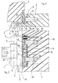
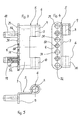
- FIG. 1 One in Figures 1 and 2 in a horizontal and vertical Sectional view shown door hinge according to the invention 1 serves one in Figures 1 and 2 only partially Door leaf 2 shown pivotable about a pivot axis 3 on a door frame shown only in Figure 1 4 to store.
- the door hinge 1 has a wing part 5, which into a hinge section 6, one to the door leaf level parallel joint-side leg 7 and one to the joint-side Leg 7 bent at right angles and thus to The door leaf level is divided into vertical legs 8 on the door leaf side.
- the joint section 6 forms two cylindrical sleeves 9, 10 with which the wing part 5 pivotable about the pivot axis 3 is stored. Approximately tangential to the cylindrical Sleeves 9, 10 extend the joint side Leg 7 of the wing part 5 into one formed in the door wing 2 Recess 11.
- leg wing-side leg 8 of the wing part 5 bends 90 degrees from the joint-side leg 7 of the wing part 5.
- This recess 15 has the shape of a Slot and corresponds in terms of their vertical extension and in terms of their width of vertical extension and the thickness of the articulated leg 7 of the Wing part 5.
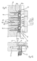
- the door wing-side holding part 20 On its base side of the recess 11 of the door leaf 2 facing away from the outer surface, the door wing-side holding part 20 four spacer sleeves 25, 26, 27, 28, which are suitable Are attached to the door leaf-side holding part 20 and towards the opening surface of the recess 11 of the Door leaf 2 extend.
- the spacer sleeves 25, 26, 27, 28 are in the door wing side Leg 8 of the wing part 5 formed openings 29, 30, 31, 32 assigned, which the spacer sleeves 25, 26, 27, 28 surrounded positively. This makes it moveable of the wing side leg 8 and thus the wing part 5 given within the recess 11 in the door leaf 2, where the only direction of movement is a movement in the horizontal direction the door leaf level is possible. A movement in the vertical direction of the door leaf level or in the thickness direction of the door leaf 2 is due to the interaction of the spacers 25, 26, 27, 28 and the openings 29, 30, 31, 32 and the guide pin 18, 19 and the guide holes 21, 22 or the guide bores 23, 24 prevented.
- the cover plate 17 has four holes 33, 34, 35, 36, those formed in the spacer sleeves 25, 26, 27, 28 Bores 37, 38, 39, 40 and with in the door part holding part 20 holes 41, 42, 43, 44 are aligned.
- the holes 33, 34, 35, 36 on the cover plate side, the spacer sleeve-side Bores 37, 38, 39, 40 and the holding part side Holes 41, 42, 43, 44 are made by four screws 45 penetrates so that the cover plate 17 and the door wing side Holding part 20 in compliance with the spacer sleeves 25, 26, 27, 28 predetermined distance between can be firmly attached to them in the recess 11 of the door leaf 2 are.
- the relative movement of the door leaf 2 with respect to the door leaf side Leg 8 of the wing part 5 and thus in relation on the door frame 4 in the horizontal direction of the door leaf level is accomplished by means of an adjusting spindle 46, between a fixing opening 47 on the cover plate side and a holder opening 48 in its axial direction fixed and rotatable between the cover plate 17th and the door leaf-side holding part 20 is held.
- the adjusting spindle 46 has an external thread section 49, with which they have a corresponding in the door wing leg 8th of the wing part 5 formed through threaded bore 50.
- the adjusting spindle 46 has one from the front the cover plate 17 actuated polygonal bore 51; at Rotation of the adjusting spindle 46 moves in one direction Door wing with respect to the pivot axis 3 in one a rotation of the adjusting spindle 46 in the opposite The door leaf 2 moves in the direction of the swivel axis 3 in the opposite direction.
- Opening 30 is by means of how, in particular 3 shows screw connection 52 of the guide bolts 18 on the base of the recess 11 of the Door wing 2 facing outer surface attached.
- the lower by means of a similar screw connection 53 Guide pin 19 between the lower opening 32 and the opening 31 arranged above it on the door leaf side Leg 8 of the wing part 5 arranged.
- the fixing opening 47 formed with the holding part Fixing opening 48 is aligned.
- the diameter the cover plate-side fixing opening 47 corresponds to that a section 54 of the polygonal bore 51 adjusting spindle 46 shown in FIG. 10; the diameter the fixing opening 48 on the holding part side corresponds to that one in FIG. 10 right end section 55 of the adjusting spindle 46.
- the upper adjusting spindle 46a in FIG. 11 in the vertical direction and the fixing openings 47a, 48a assigned to it are at this embodiment between the top 25 and the one thereon following spacer sleeve 26 arranged.
- the cylindrical guide pin 60 and the round guide hole 61 is approximately in the vertical direction at the center of the door leaf level vertical leg 8 side of the wing part 5 or the door leaf-side holding part 20 is arranged.
Landscapes
- Engineering & Computer Science (AREA)
- Mechanical Engineering (AREA)
- Hinges (AREA)
Applications Claiming Priority (2)
| Application Number | Priority Date | Filing Date | Title |
|---|---|---|---|
| DE19842769 | 1998-09-18 | ||
| DE19842769A DE19842769C2 (de) | 1998-01-21 | 1998-09-18 | Türband zur schwenkbaren Anbringung eines Türflügels an einem Türrahmen |
Publications (3)
| Publication Number | Publication Date |
|---|---|
| EP0987393A2 true EP0987393A2 (fr) | 2000-03-22 |
| EP0987393A3 EP0987393A3 (fr) | 2001-02-28 |
| EP0987393B1 EP0987393B1 (fr) | 2004-10-27 |
Family
ID=7881385
Family Applications (1)
| Application Number | Title | Priority Date | Filing Date |
|---|---|---|---|
| EP99113823A Expired - Lifetime EP0987393B1 (fr) | 1998-09-18 | 1999-07-15 | Paumelle pour le montage pivotant d'un vantail de porte sur un cadre |
Country Status (2)
| Country | Link |
|---|---|
| EP (1) | EP0987393B1 (fr) |
| AT (1) | ATE280880T1 (fr) |
Cited By (2)
| Publication number | Priority date | Publication date | Assignee | Title |
|---|---|---|---|---|
| US6721992B2 (en) | 2002-06-19 | 2004-04-20 | Oren Cotton | Boat hinge cover |
| DE10152366C5 (de) * | 2001-10-24 | 2004-12-02 | Simonswerk, Gmbh | Aufnahmevorrichtung zur in Türdicken- oder Türquerrichtung verstellbaren Halterung eines Bandlappens einer Türflügelschwenkhalterung an einem Hohlprofil, z.B. einem Aluminiumprofil |
Family Cites Families (2)
| Publication number | Priority date | Publication date | Assignee | Title |
|---|---|---|---|---|
| DE7825189U1 (de) * | 1978-08-24 | 1978-11-30 | Oni-Metallwarenfabriken Guenter & Co, 4973 Vlotho | Verstellbares tuerband |
| NO304158B1 (no) * | 1996-11-21 | 1998-11-02 | Grorud Ind As | Anordning ved en d°rhengselkonstruksjon av innsneppingstypen |
-
1999
- 1999-07-15 AT AT99113823T patent/ATE280880T1/de not_active IP Right Cessation
- 1999-07-15 EP EP99113823A patent/EP0987393B1/fr not_active Expired - Lifetime
Cited By (2)
| Publication number | Priority date | Publication date | Assignee | Title |
|---|---|---|---|---|
| DE10152366C5 (de) * | 2001-10-24 | 2004-12-02 | Simonswerk, Gmbh | Aufnahmevorrichtung zur in Türdicken- oder Türquerrichtung verstellbaren Halterung eines Bandlappens einer Türflügelschwenkhalterung an einem Hohlprofil, z.B. einem Aluminiumprofil |
| US6721992B2 (en) | 2002-06-19 | 2004-04-20 | Oren Cotton | Boat hinge cover |
Also Published As
| Publication number | Publication date |
|---|---|
| EP0987393A3 (fr) | 2001-02-28 |
| EP0987393B1 (fr) | 2004-10-27 |
| ATE280880T1 (de) | 2004-11-15 |
Similar Documents
| Publication | Publication Date | Title |
|---|---|---|
| EP2297418B1 (fr) | Charniere | |
| DE3323403C2 (fr) | ||
| EP0285229B2 (fr) | Charnière réglable, en particulier pour portes | |
| DE3008223A1 (de) | Drehbeschlag fuer ganzglastueren | |
| DE19947670B4 (de) | Drehband für Türen oder Fenster | |
| DE2656305C2 (de) | Schnäpperscharnier | |
| EP2754813B1 (fr) | Charnière, notamment pour portes et fenêtres en plastique | |
| DE10110311C2 (de) | Scharnier mit Höhenverstellschraube | |
| EP0223186B1 (fr) | Penture réglable pour portes ou fenêtres | |
| EP1900896B1 (fr) | Penture pour un vantail de porte se fermant automatiquement | |
| DE9200563U1 (de) | Dreidimensional verstellbares Aufschraubband für Tür- oder Fensterflügel | |
| EP0215281A2 (fr) | Palier pour un battant de fenêtre, porte ou similaire | |
| DE20017995U1 (de) | Beschlag für Schiebetüren | |
| DE19842769C2 (de) | Türband zur schwenkbaren Anbringung eines Türflügels an einem Türrahmen | |
| EP0987393A2 (fr) | Paumelle pour le montage pivotant d'un vantail de porte sur un cadre | |
| EP0487825B1 (fr) | Ferrure arrangée en feuillure pour aile pivotante, en particulier pour aile oscillo-battante, de fenêtre ou portes | |
| DE2149503C3 (de) | Möbelscharnier | |
| DE19649071A1 (de) | Beschlag zum Befestigen eines Türflügels, insbesondere eines Türflügels einer Duschabtrennung aus Glas, Kunststoff oder dergleichen | |
| EP1512817B1 (fr) | Ferrure pour portes, fenêtres ou similaires | |
| DE19742143C1 (de) | Scharnierelement für ein Flügelteil | |
| WO2004038145A1 (fr) | Charniere | |
| DE2634268A1 (de) | Einjustierbares unteres ecklager fuer dreh/kippfluegel von fenstern, tueren o.dgl. | |
| EP0340455B2 (fr) | Pivot pour la connexion de deux battants d'une fenêtre, d'une porte ou similaire | |
| DE19642638A1 (de) | Türband | |
| DE9202860U1 (de) | Scharnier für Türflügel von Möbeln mit doppelter Einstellmöglichkeit |
Legal Events
| Date | Code | Title | Description |
|---|---|---|---|
| PUAI | Public reference made under article 153(3) epc to a published international application that has entered the european phase |
Free format text: ORIGINAL CODE: 0009012 |
|
| AK | Designated contracting states |
Kind code of ref document: A2 Designated state(s): AT BE CH CY DE DK ES FI FR GB GR IE IT LI LU MC NL PT SE |
|
| AX | Request for extension of the european patent |
Free format text: AL;LT;LV;MK;RO;SI |
|
| PUAL | Search report despatched |
Free format text: ORIGINAL CODE: 0009013 |
|
| AK | Designated contracting states |
Kind code of ref document: A3 Designated state(s): AT BE CH CY DE DK ES FI FR GB GR IE IT LI LU MC NL PT SE |
|
| AX | Request for extension of the european patent |
Free format text: AL;LT;LV;MK;RO;SI |
|
| 17P | Request for examination filed |
Effective date: 20010802 |
|
| AKX | Designation fees paid |
Free format text: AT BE CH CY DE DK ES FI FR GB GR IE IT LI LU MC NL PT SE |
|
| 17Q | First examination report despatched |
Effective date: 20030213 |
|
| GRAP | Despatch of communication of intention to grant a patent |
Free format text: ORIGINAL CODE: EPIDOSNIGR1 |
|
| GRAS | Grant fee paid |
Free format text: ORIGINAL CODE: EPIDOSNIGR3 |
|
| GRAA | (expected) grant |
Free format text: ORIGINAL CODE: 0009210 |
|
| AK | Designated contracting states |
Kind code of ref document: B1 Designated state(s): AT BE CH CY DE DK ES FI FR GB GR IE IT LI LU MC NL PT SE |
|
| PG25 | Lapsed in a contracting state [announced via postgrant information from national office to epo] |
Ref country code: NL Free format text: LAPSE BECAUSE OF FAILURE TO SUBMIT A TRANSLATION OF THE DESCRIPTION OR TO PAY THE FEE WITHIN THE PRESCRIBED TIME-LIMIT Effective date: 20041027 Ref country code: IT Free format text: LAPSE BECAUSE OF FAILURE TO SUBMIT A TRANSLATION OF THE DESCRIPTION OR TO PAY THE FEE WITHIN THE PRESCRIBED TIME-LIMIT;WARNING: LAPSES OF ITALIAN PATENTS WITH EFFECTIVE DATE BEFORE 2007 MAY HAVE OCCURRED AT ANY TIME BEFORE 2007. THE CORRECT EFFECTIVE DATE MAY BE DIFFERENT FROM THE ONE RECORDED. Effective date: 20041027 Ref country code: IE Free format text: LAPSE BECAUSE OF FAILURE TO SUBMIT A TRANSLATION OF THE DESCRIPTION OR TO PAY THE FEE WITHIN THE PRESCRIBED TIME-LIMIT Effective date: 20041027 Ref country code: GB Free format text: LAPSE BECAUSE OF FAILURE TO SUBMIT A TRANSLATION OF THE DESCRIPTION OR TO PAY THE FEE WITHIN THE PRESCRIBED TIME-LIMIT Effective date: 20041027 Ref country code: FR Free format text: LAPSE BECAUSE OF FAILURE TO SUBMIT A TRANSLATION OF THE DESCRIPTION OR TO PAY THE FEE WITHIN THE PRESCRIBED TIME-LIMIT Effective date: 20041027 Ref country code: FI Free format text: LAPSE BECAUSE OF FAILURE TO SUBMIT A TRANSLATION OF THE DESCRIPTION OR TO PAY THE FEE WITHIN THE PRESCRIBED TIME-LIMIT Effective date: 20041027 |
|
| REG | Reference to a national code |
Ref country code: GB Ref legal event code: FG4D Free format text: NOT ENGLISH |
|
| REG | Reference to a national code |
Ref country code: CH Ref legal event code: EP |
|
| REG | Reference to a national code |
Ref country code: IE Ref legal event code: FG4D Free format text: GERMAN |
|
| REF | Corresponds to: |
Ref document number: 59910937 Country of ref document: DE Date of ref document: 20041202 Kind code of ref document: P |
|
| PG25 | Lapsed in a contracting state [announced via postgrant information from national office to epo] |
Ref country code: SE Free format text: LAPSE BECAUSE OF FAILURE TO SUBMIT A TRANSLATION OF THE DESCRIPTION OR TO PAY THE FEE WITHIN THE PRESCRIBED TIME-LIMIT Effective date: 20050127 Ref country code: GR Free format text: LAPSE BECAUSE OF FAILURE TO SUBMIT A TRANSLATION OF THE DESCRIPTION OR TO PAY THE FEE WITHIN THE PRESCRIBED TIME-LIMIT Effective date: 20050127 Ref country code: DK Free format text: LAPSE BECAUSE OF FAILURE TO SUBMIT A TRANSLATION OF THE DESCRIPTION OR TO PAY THE FEE WITHIN THE PRESCRIBED TIME-LIMIT Effective date: 20050127 |
|
| PG25 | Lapsed in a contracting state [announced via postgrant information from national office to epo] |
Ref country code: ES Free format text: LAPSE BECAUSE OF FAILURE TO SUBMIT A TRANSLATION OF THE DESCRIPTION OR TO PAY THE FEE WITHIN THE PRESCRIBED TIME-LIMIT Effective date: 20050207 |
|
| NLV1 | Nl: lapsed or annulled due to failure to fulfill the requirements of art. 29p and 29m of the patents act | ||
| REG | Reference to a national code |
Ref country code: IE Ref legal event code: FD4D |
|
| GBV | Gb: ep patent (uk) treated as always having been void in accordance with gb section 77(7)/1977 [no translation filed] |
Effective date: 20041027 |
|
| PG25 | Lapsed in a contracting state [announced via postgrant information from national office to epo] |
Ref country code: LU Free format text: LAPSE BECAUSE OF NON-PAYMENT OF DUE FEES Effective date: 20050715 Ref country code: CY Free format text: LAPSE BECAUSE OF FAILURE TO SUBMIT A TRANSLATION OF THE DESCRIPTION OR TO PAY THE FEE WITHIN THE PRESCRIBED TIME-LIMIT Effective date: 20050715 Ref country code: AT Free format text: LAPSE BECAUSE OF NON-PAYMENT OF DUE FEES Effective date: 20050715 |
|
| PG25 | Lapsed in a contracting state [announced via postgrant information from national office to epo] |
Ref country code: MC Free format text: LAPSE BECAUSE OF NON-PAYMENT OF DUE FEES Effective date: 20050731 Ref country code: LI Free format text: LAPSE BECAUSE OF NON-PAYMENT OF DUE FEES Effective date: 20050731 Ref country code: CH Free format text: LAPSE BECAUSE OF NON-PAYMENT OF DUE FEES Effective date: 20050731 Ref country code: BE Free format text: LAPSE BECAUSE OF NON-PAYMENT OF DUE FEES Effective date: 20050731 |
|
| PLBE | No opposition filed within time limit |
Free format text: ORIGINAL CODE: 0009261 |
|
| STAA | Information on the status of an ep patent application or granted ep patent |
Free format text: STATUS: NO OPPOSITION FILED WITHIN TIME LIMIT |
|
| 26N | No opposition filed |
Effective date: 20050728 |
|
| EN | Fr: translation not filed | ||
| REG | Reference to a national code |
Ref country code: CH Ref legal event code: PL |
|
| BERE | Be: lapsed |
Owner name: *SIMONSWERK G.M.B.H. Effective date: 20050731 |
|
| PG25 | Lapsed in a contracting state [announced via postgrant information from national office to epo] |
Ref country code: PT Free format text: LAPSE BECAUSE OF NON-PAYMENT OF DUE FEES Effective date: 20050327 |
|
| PGFP | Annual fee paid to national office [announced via postgrant information from national office to epo] |
Ref country code: DE Payment date: 20090918 Year of fee payment: 11 |
|
| PG25 | Lapsed in a contracting state [announced via postgrant information from national office to epo] |
Ref country code: DE Free format text: LAPSE BECAUSE OF NON-PAYMENT OF DUE FEES Effective date: 20110201 |
|
| REG | Reference to a national code |
Ref country code: DE Ref legal event code: R119 Ref document number: 59910937 Country of ref document: DE Effective date: 20110201 |