EP0987428A2 - Procédé pour commander le débit de purge d'un canister et soupape de commande utilisée a cet effet - Google Patents
Procédé pour commander le débit de purge d'un canister et soupape de commande utilisée a cet effet Download PDFInfo
- Publication number
- EP0987428A2 EP0987428A2 EP99117906A EP99117906A EP0987428A2 EP 0987428 A2 EP0987428 A2 EP 0987428A2 EP 99117906 A EP99117906 A EP 99117906A EP 99117906 A EP99117906 A EP 99117906A EP 0987428 A2 EP0987428 A2 EP 0987428A2
- Authority
- EP
- European Patent Office
- Prior art keywords
- flow
- vacuum
- passages
- vapor
- port
- Prior art date
- Legal status (The legal status is an assumption and is not a legal conclusion. Google has not performed a legal analysis and makes no representation as to the accuracy of the status listed.)
- Granted
Links
Images



Classifications
-
- F—MECHANICAL ENGINEERING; LIGHTING; HEATING; WEAPONS; BLASTING
- F02—COMBUSTION ENGINES; HOT-GAS OR COMBUSTION-PRODUCT ENGINE PLANTS
- F02M—SUPPLYING COMBUSTION ENGINES IN GENERAL WITH COMBUSTIBLE MIXTURES OR CONSTITUENTS THEREOF
- F02M33/00—Other apparatus for treating combustion-air, fuel or fuel-air mixture
-
- F—MECHANICAL ENGINEERING; LIGHTING; HEATING; WEAPONS; BLASTING
- F02—COMBUSTION ENGINES; HOT-GAS OR COMBUSTION-PRODUCT ENGINE PLANTS
- F02M—SUPPLYING COMBUSTION ENGINES IN GENERAL WITH COMBUSTIBLE MIXTURES OR CONSTITUENTS THEREOF
- F02M25/00—Engine-pertinent apparatus for adding non-fuel substances or small quantities of secondary fuel to combustion-air, main fuel or fuel-air mixture
- F02M25/08—Engine-pertinent apparatus for adding non-fuel substances or small quantities of secondary fuel to combustion-air, main fuel or fuel-air mixture adding fuel vapours drawn from engine fuel reservoir
- F02M25/0836—Arrangement of valves controlling the admission of fuel vapour to an engine, e.g. valve being disposed between fuel tank or absorption canister and intake manifold
-
- F—MECHANICAL ENGINEERING; LIGHTING; HEATING; WEAPONS; BLASTING
- F02—COMBUSTION ENGINES; HOT-GAS OR COMBUSTION-PRODUCT ENGINE PLANTS
- F02M—SUPPLYING COMBUSTION ENGINES IN GENERAL WITH COMBUSTIBLE MIXTURES OR CONSTITUENTS THEREOF
- F02M25/00—Engine-pertinent apparatus for adding non-fuel substances or small quantities of secondary fuel to combustion-air, main fuel or fuel-air mixture
- F02M25/08—Engine-pertinent apparatus for adding non-fuel substances or small quantities of secondary fuel to combustion-air, main fuel or fuel-air mixture adding fuel vapours drawn from engine fuel reservoir
- F02M2025/0845—Electromagnetic valves
Definitions
- the present invention relates to devices of the type known as vapor management valves (VMV) which are employed for controlling purge flow of fuel tank vapor from a storage canister to the intake manifold of an internal combustion engine.
- VMV vapor management valves
- Such devices are employed in light motor vehicles where evaporation of tank fuel is prevented in the engine off condition by collection of the fuel vapors in a storage canister, typically of the type containing adsorbent granular charcoal.
- VMVs provide an electrically operated bleed valve (EVR) for bleeding atmospheric air to a signal pressure chamber supplied with intake manifold vacuum for providing a vacuum control signal to one side of a pressure responsive diaphragm.
- EMR electrically operated bleed valve
- the diaphragm operates a regulator valve member for controlling vapor flow between an inlet connected to the vapor storage canister and an outlet connected to the engine intake manifold.
- the diaphragm is preloaded by a spring to bias the diaphragm valve member closed preventing vapor flow to the engine manifold until a predetermined pressure differential is experienced by the diaphragm.
- An example of such a known VMV is that shown and described in U.S. Patent 5,277,167.
- the known valve assembly indicated generally at 1 has an EVR indicated generally at 2 which controls atmospheric vent flow through a filter 5 and coil passage 3 to an outlet passage 4 which supplies air flow through an inlet passage 6 of a vacuum pressure signal chamber 8 which is supplied with engine manifold vacuum through a connector 10 and a single bleed orifice 12.
- the pressure in chamber 8 is applied to one side of a pressure responsive diaphragm 14 which moves a regulator valve member 16 with respect to a valve seat 17 for controlling flow between vacuum connector 18 connected to the engine intake manifold and a fuel vapor purge inlet connector 20 connected to a fuel vapor canister 22 which is connected to a fuel tank 24.
- Diaphragm 14 is preloaded by a spring 26 to prevent opening of the valve 19 until a predetermined pressure differential exists across the diaphragm 14 in a manner well known in the art.
- VMV vacuum flow rate out of the vacuum pressure signal chamber increases with increasing engine manifold vacuum.
- high engine manifold vacuum levels reduced manifold absolute pressure
- sonic flow choking or limiting occurs in the port thereby preventing further increases in flow with increasing engine manifold vacuum.
- the present invention provides a VMV having an electrically operated bleed valve or EVR controlling atmospheric vent flow to a vacuum signal pressure chamber which controls the pressure on one side of a diaphragm for operating a purge flow regulator valve.
- the vacuum signal to the vacuum signal pressure chamber is supplied vacuum through a plurality of flow restricting passages in the connector and which restrict flow but prevent the occurrence of sonic flow choking.
- a pair of restricting orifices are disposed in spaced relationship fluidically in series in the vacuum signal port connection; and, in another embodiment a laminar flow element comprising plurality of laminar flow passages are provided fluidically in parallel in the vacuum signal port to the control pressure chamber for the diaphragm. Porous sintered metal or fibrous material may be employed for the latter parallel passages.
- a single restrictive orifice is disposed fluidically in series with a laminar flow element.
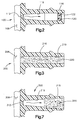
- the present invention is illustrated at 100 as comprising a VMV similar to FIG. 1 but having an inlet fitting illustrated at 116 and which has a modification to the prior art wherein the wall 108 of the vacuum signal pressure chamber is ported at 112 with a restricting orifice; and, the inlet passage in connector 116 has a second orifice 120 formed in the connector passage 119 and which is spaced from the orifice 112 and fluidically in series therewith.
- the orifice 120 may be formed in a suitable washer or insert 122 pressed into the passage 119.
- the downstream orifice 122 are sized to maintain the same pressure ratio thereacross as the upstream orifice 112..
- orifice 112 has a diameter of about .025 inches (0.63 mm) and downstream orifice of about .036 inches (.91 mm) for the flow characteristics of FIG. 6.
- orifices 112, 120 are sized differently to give the desired vacuum bleed flow; however, the two orifices function to prevent the occurrence of sonic flow choking.
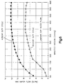
- the EVR bleed flow through the atmospheric vent is shown plotted for the range of intake manifold vacuum encountered during engine operation, with the upper curve plotted for the prior art valve of FIG. 1 and the lower curve showing the flow as a function of intake manifold vacuum for the dual orifices of FIG. 2 for the present invention.
- the vapor purge flow for the VMV is plotted as a function of engine intake manifold vacuum for the prior art valve of FIG. 1 and the flow for present invention as illustrated in FIG. 2.
- the upper set of flow curves in FIG. 5 was obtained with a 43.5% EVR electrical signal duty cycle for the prior art and a 42.5 % EVR electrical signal duty cycle for the valve of the present invention.
- the lower set of curves in FIG. 5 was obtained for a 37% EVR electrical signal duty cycle for the two orifice arrangement of FIG. 2; and, a 38% EVR electrical signal duty cycle was utilized for the prior art valve of FIG. 1.
- the vapor purge flow of the VMV of the present invention as embodied in FIG. 3 is plotted as a function of engine intake manifold vacuum for two different percentage EVR electrical signal duty cycles namely 35.5% and 42% and illustrates the substantially constant vapor flow achieved at higher levels of engine intake manifold vacuum (lower manifold absolute pressure) achieved by the present invention.
- FIG. 3 an alternative arrangement of the invention is illustrated generally at 200 in which the vacuum inlet fitting 216 has the flow passage 219 thereof filled with fluidically parallel laminar flow passages formed in a laminar flow element comprising a porous filter denoted by reference numeral 220 which may comprise fibrous material or alternatively porous sintered metal, or other suitable material.
- Filter 220 provides communication with the vacuum pressure signal chamber 208, it being understood that the remaining portions of the VMV of FIG. 3 are identical to those of the prior art valve of FIG. 1.
- FIG. 7 another embodiment of the invention is illustrated and indicated generally at 300 and has the vacuum signal control pressure chamber 308 communicating via orifice 312 with a flow passage 319 formed in vacuum inlet connector 316 which, it will be understood, is adapted for connection to the engine intake manifold by a suitable hose (not shown) but which connection is indicated by dashed outline and reference numeral 15 in FIG. 1.
- Passage 319 has received adjacent the end remote from orifice 312 a laminar flow element 320 which may be of the same material as the flow element 220 in the embodiment of FIG. 3.
- the element 320 in the embodiment of FIG. 7 is thus spaced along the passage 319 from the orifice 312.
- the filter material 220, 320 in the embodiments of FIG. 3 and FIG. 7 is high density polyethylene (HDPE) material having a 65 micron pore size, fifty percent (50%) pore volume. It will be understood that the flow through the elements 220, 320 is substantially laminar due to the small diameter of the pores; and, the pressure drop through the filter is approximately a linear function of flow and the pressure drop is a function of the filter area and filter length.
- HDPE high density polyethylene
- FIG. 7 thus combines an orifice and a laminar flow element in series. This enables the flow to be tailored thereby minimizing the flow change upon a sudden change of the vacuum applied to the vacuum inlet connector.
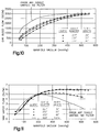
- the EVR bleed flow through the dual orifices 112, 122 of the embodiment of FIG. 2 is plotted as a function of engine intake manifold vacuum.
- a family of curves are plotted for different ratios of the diameter of the orifice 122 to the diameter of orifice 112 over the range of manifold vacuum encountered during engine service. It will be apparent from FIG. 8 that the curves drawn through the data for the dual orifice configuration of FIG. 2, as compared with solid line curve the prior art single orifice, show a dramatic change in the EVR bleed flow with the present invention, particularly in the range of manifold vacuums of greatest concern namely, 200 through 500 millimeters HG manifold vacuum.
- FIG. 9 a family of graphs are plotted for the fuel vapor flow through the VMV to the intake manifold (through connectors 116, 216, 316) for different values of the ratio of orifice 122 to orifice 112. It will be seen from FIG. 9 that by appropriate sizing of the orifices 122, 112 significant improvement and changes in the characteristics of the fuel vapor flow may be obtained as compared to the solid line curve for the prior art configuration.
- FIG. 10 a graph plotting the EVR bleed flow as a function of engine intake manifold vacuum is illustrated for the prior art single orifice construction of FIG. 1; and curves are plotted for data taken utilizing the single orifice in combination with laminar flow element embodiment of FIG. 7.
- the three curves drawn through the data taken for various orifice diameters show a dramatic linearization of the EVR bleed flow as compared with the curve for the prior art single orifice arrangement of FIG. 1, particularly in the range 200 to 500 mm Hg manifold vacuum.
- the fuel vapor flow to the intake manifold through connector 316 of FIG. 7 is shown for a family of curves drawn through the data plotted for vapor flow as a function of engine manifold vacuum. It will be seen that the combination orifice and filter embodiment of FIG. 7 produces dramatic leveling of the fuel vapor flow over the engine manifold vacuum range of 200 through 500 millimeters HG as compared with the prior art construction of FIG. 1.
- the present invention thus provides a simple and low cost technique for modifying an existing vapor management valve to prevent the occurrence sonic flow choking in the vacuum signal port which would restrict bleed flow therethrough from tracking engine manifold vacuum level changes.
- the present invention thus provides substantially constant vapor flow through the VMV at high levels of engine manifold vacuum (low manifold absolute pressure) particularly at "tip-out” because sonic choking of vacuum signal bleed flow to the signal pressure chamber is prevented.
Landscapes
- Engineering & Computer Science (AREA)
- Chemical & Material Sciences (AREA)
- Combustion & Propulsion (AREA)
- Mechanical Engineering (AREA)
- General Engineering & Computer Science (AREA)
- Supplying Secondary Fuel Or The Like To Fuel, Air Or Fuel-Air Mixtures (AREA)
- Safety Valves (AREA)
Applications Claiming Priority (2)
| Application Number | Priority Date | Filing Date | Title |
|---|---|---|---|
| US09/154,117 US5893354A (en) | 1998-09-16 | 1998-09-16 | Method of controlling fuel vapor canister purge flow and vapor management valve therefor |
| US154117 | 1998-09-16 |
Publications (3)
| Publication Number | Publication Date |
|---|---|
| EP0987428A2 true EP0987428A2 (fr) | 2000-03-22 |
| EP0987428A3 EP0987428A3 (fr) | 2000-11-02 |
| EP0987428B1 EP0987428B1 (fr) | 2004-01-14 |
Family
ID=22550071
Family Applications (1)
| Application Number | Title | Priority Date | Filing Date |
|---|---|---|---|
| EP99117906A Expired - Lifetime EP0987428B1 (fr) | 1998-09-16 | 1999-09-13 | Procédé pour commander le débit de purge d'un canister et soupape de commande utilisée a cet effet |
Country Status (7)
| Country | Link |
|---|---|
| US (1) | US5893354A (fr) |
| EP (1) | EP0987428B1 (fr) |
| JP (1) | JP2000097114A (fr) |
| KR (1) | KR20000023104A (fr) |
| CA (1) | CA2282076C (fr) |
| DE (1) | DE69914143T2 (fr) |
| ES (1) | ES2212439T3 (fr) |
Cited By (1)
| Publication number | Priority date | Publication date | Assignee | Title |
|---|---|---|---|---|
| WO2006072509A1 (fr) * | 2005-01-07 | 2006-07-13 | Siemens Vdo Automotive Ag | Servomoteur pour l'actionnement d'une soupape d'injection de carburant |
Families Citing this family (9)
| Publication number | Priority date | Publication date | Assignee | Title |
|---|---|---|---|---|
| FR2753658B1 (fr) * | 1996-09-26 | 1998-12-11 | Dispositif de puisage de carburant pour reservoir de vehicules automobiles | |
| US6205982B1 (en) * | 1998-05-15 | 2001-03-27 | Chrysler Corporation | Proportional purge solenoid control system |
| US6119661A (en) * | 1998-08-18 | 2000-09-19 | Eaton Corporation | Pressure compensating vapor management valve |
| JP3946368B2 (ja) * | 1998-12-03 | 2007-07-18 | 三菱電機株式会社 | 燃料蒸発ガス排出抑止装置 |
| US20110100336A1 (en) * | 2009-11-04 | 2011-05-05 | Genz Thomas R | Vapor recovery system having vacuum break fitting with flow restrictor |
| US9222443B2 (en) | 2012-04-11 | 2015-12-29 | Ford Global Technologies, Llc | Method for purging fuel vapors to an engine |
| US9027533B2 (en) | 2012-07-26 | 2015-05-12 | Ford Global Technologies, Llc | Method and system for fuel system control |
| US10890474B2 (en) | 2018-09-18 | 2021-01-12 | Swagelok Company | Fluid monitoring module arrangements |
| US10883865B2 (en) | 2018-09-19 | 2021-01-05 | Swagelok Company | Flow restricting fluid component |
Family Cites Families (14)
| Publication number | Priority date | Publication date | Assignee | Title |
|---|---|---|---|---|
| GB1307533A (en) * | 1970-01-15 | 1973-02-21 | Dunlop Holdings Ltd | Pressure reducing devices |
| DE2127198A1 (de) * | 1971-06-02 | 1972-12-14 | Wiesner H | Festwiderstand für fluidische Ströme |
| JPS5920884B2 (ja) * | 1981-03-09 | 1984-05-16 | 東京瓦斯株式会社 | 騒音・振動防止のための減圧装置 |
| DE8904867U1 (de) * | 1989-04-18 | 1990-08-16 | CIWJ Compagnie Internationale Du Water Jet, Rothbach | Einsatzorgan |
| JPH0586923A (ja) * | 1991-07-26 | 1993-04-06 | Nippon Soken Inc | 蒸発燃料パージ装置を有する内燃機関 |
| US5188141A (en) * | 1991-12-03 | 1993-02-23 | Siemens Automotive Limited | Vacuum boost valve |
| US5390644A (en) * | 1991-12-27 | 1995-02-21 | Nippondenso Co., Ltd. | Method for producing fuel/air mixture for combustion engine |
| JP2920805B2 (ja) * | 1992-03-31 | 1999-07-19 | 本田技研工業株式会社 | 内燃機関の蒸発燃料制御装置 |
| SE500543C2 (sv) * | 1992-05-12 | 1994-07-11 | Volvo Ab | Bränslesystem för motorfordon |
| DE4229110C1 (de) * | 1992-09-01 | 1993-10-07 | Freudenberg Carl Fa | Vorrichtung zum vorübergehenden Speichern und dosierten Einspeisen von im Freiraum einer Tankanlage befindlichen flüchtigen Kraftstoffbestandteilen in das Ansaugrohr einer Verbrennungskraftmaschine |
| US5728298A (en) * | 1992-10-29 | 1998-03-17 | Cuno, Incorporated | Filter element and method for the manufacture thereof |
| US5277167A (en) * | 1993-02-04 | 1994-01-11 | Lectron Products, Inc. | Vapor management valve |
| US5630403A (en) * | 1996-06-13 | 1997-05-20 | Siemens Electric Limited | Force-balanced sonic flow emission control valve |
| US5749349A (en) * | 1996-10-24 | 1998-05-12 | Eaton Corporation | Fuel vapor control system |
-
1998
- 1998-09-16 US US09/154,117 patent/US5893354A/en not_active Expired - Fee Related
-
1999
- 1999-09-10 CA CA002282076A patent/CA2282076C/fr not_active Expired - Fee Related
- 1999-09-13 KR KR1019990038942A patent/KR20000023104A/ko not_active Ceased
- 1999-09-13 DE DE69914143T patent/DE69914143T2/de not_active Expired - Fee Related
- 1999-09-13 ES ES99117906T patent/ES2212439T3/es not_active Expired - Lifetime
- 1999-09-13 EP EP99117906A patent/EP0987428B1/fr not_active Expired - Lifetime
- 1999-09-16 JP JP11262080A patent/JP2000097114A/ja active Pending
Cited By (2)
| Publication number | Priority date | Publication date | Assignee | Title |
|---|---|---|---|---|
| WO2006072509A1 (fr) * | 2005-01-07 | 2006-07-13 | Siemens Vdo Automotive Ag | Servomoteur pour l'actionnement d'une soupape d'injection de carburant |
| US7906888B2 (en) | 2005-01-07 | 2011-03-15 | Continental Automotive Gmbh | Actuator for actuating a fuel injection valve |
Also Published As
| Publication number | Publication date |
|---|---|
| EP0987428A3 (fr) | 2000-11-02 |
| DE69914143D1 (de) | 2004-02-19 |
| JP2000097114A (ja) | 2000-04-04 |
| CA2282076C (fr) | 2004-07-06 |
| DE69914143T2 (de) | 2004-10-28 |
| US5893354A (en) | 1999-04-13 |
| ES2212439T3 (es) | 2004-07-16 |
| EP0987428B1 (fr) | 2004-01-14 |
| KR20000023104A (ko) | 2000-04-25 |
| CA2282076A1 (fr) | 2000-03-16 |
Similar Documents
| Publication | Publication Date | Title |
|---|---|---|
| US5970958A (en) | Fuel vapor purge control | |
| US5083546A (en) | Two-stage high flow purge valve | |
| US5429099A (en) | Anti-permeation filter for vapor management valve | |
| US5277167A (en) | Vapor management valve | |
| US5289811A (en) | Purge control device | |
| US5893354A (en) | Method of controlling fuel vapor canister purge flow and vapor management valve therefor | |
| US6053151A (en) | Automotive evaporative emission leak detection system and module | |
| CA1090664A (fr) | Soupape regulatrice d'evaporation de reservoir de combustible | |
| US6810862B2 (en) | Fuel tank vapor relief valve and method of making same | |
| WO1993002282A1 (fr) | Electrovanne de purge de cartouche filtrante a pentes multiples | |
| US6318405B1 (en) | Fuel pressure regulator with fluidic assist | |
| US4381753A (en) | Evaporative emission control device of an internal combustion engine for vehicle use | |
| US4026258A (en) | Control device for regulating the amount of collected fuel and/or oil vapors which are delivered to the combustion chamber of an internal combustion | |
| EP0877310B1 (fr) | Amortissement de résonance dans un régulateur de débit | |
| JPH05312113A (ja) | 燃料蒸発ガス拡散防止装置 | |
| US5533488A (en) | Vacuum sustaining valve | |
| JP4247830B2 (ja) | 蒸発燃料処理装置 | |
| EP0051452A1 (fr) | Système de contrôle à dépression | |
| JPH0633844A (ja) | 燃料タンク内圧力制御装置 | |
| JPH11107863A (ja) | 内燃機関の蒸発燃料制御装置 | |
| JPH0719364A (ja) | 電磁弁 |
Legal Events
| Date | Code | Title | Description |
|---|---|---|---|
| PUAI | Public reference made under article 153(3) epc to a published international application that has entered the european phase |
Free format text: ORIGINAL CODE: 0009012 |
|
| AK | Designated contracting states |
Kind code of ref document: A2 Designated state(s): DE ES FR GB IT SE |
|
| AX | Request for extension of the european patent |
Free format text: AL;LT;LV;MK;RO;SI |
|
| PUAL | Search report despatched |
Free format text: ORIGINAL CODE: 0009013 |
|
| AK | Designated contracting states |
Kind code of ref document: A3 Designated state(s): AT BE CH CY DE DK ES FI FR GB GR IE IT LI LU MC NL PT SE |
|
| AX | Request for extension of the european patent |
Free format text: AL;LT;LV;MK;RO;SI |
|
| 17P | Request for examination filed |
Effective date: 20010321 |
|
| AKX | Designation fees paid |
Free format text: DE ES FR GB IT SE |
|
| GRAP | Despatch of communication of intention to grant a patent |
Free format text: ORIGINAL CODE: EPIDOSNIGR1 |
|
| GRAS | Grant fee paid |
Free format text: ORIGINAL CODE: EPIDOSNIGR3 |
|
| GRAA | (expected) grant |
Free format text: ORIGINAL CODE: 0009210 |
|
| AK | Designated contracting states |
Kind code of ref document: B1 Designated state(s): DE ES FR GB IT SE |
|
| REG | Reference to a national code |
Ref country code: GB Ref legal event code: FG4D |
|
| REF | Corresponds to: |
Ref document number: 69914143 Country of ref document: DE Date of ref document: 20040219 Kind code of ref document: P |
|
| REG | Reference to a national code |
Ref country code: SE Ref legal event code: TRGR |
|
| REG | Reference to a national code |
Ref country code: ES Ref legal event code: FG2A Ref document number: 2212439 Country of ref document: ES Kind code of ref document: T3 |
|
| ET | Fr: translation filed | ||
| PLBE | No opposition filed within time limit |
Free format text: ORIGINAL CODE: 0009261 |
|
| STAA | Information on the status of an ep patent application or granted ep patent |
Free format text: STATUS: NO OPPOSITION FILED WITHIN TIME LIMIT |
|
| 26N | No opposition filed |
Effective date: 20041015 |
|
| PGFP | Annual fee paid to national office [announced via postgrant information from national office to epo] |
Ref country code: ES Payment date: 20050919 Year of fee payment: 7 |
|
| PGFP | Annual fee paid to national office [announced via postgrant information from national office to epo] |
Ref country code: GB Payment date: 20060804 Year of fee payment: 8 |
|
| PGFP | Annual fee paid to national office [announced via postgrant information from national office to epo] |
Ref country code: FR Payment date: 20060906 Year of fee payment: 8 |
|
| PGFP | Annual fee paid to national office [announced via postgrant information from national office to epo] |
Ref country code: DE Payment date: 20060929 Year of fee payment: 8 |
|
| PGFP | Annual fee paid to national office [announced via postgrant information from national office to epo] |
Ref country code: IT Payment date: 20060930 Year of fee payment: 8 |
|
| PGFP | Annual fee paid to national office [announced via postgrant information from national office to epo] |
Ref country code: SE Payment date: 20060908 Year of fee payment: 8 |
|
| PG25 | Lapsed in a contracting state [announced via postgrant information from national office to epo] |
Ref country code: SE Free format text: LAPSE BECAUSE OF NON-PAYMENT OF DUE FEES Effective date: 20070914 |
|
| EUG | Se: european patent has lapsed | ||
| GBPC | Gb: european patent ceased through non-payment of renewal fee |
Effective date: 20070913 |
|
| PG25 | Lapsed in a contracting state [announced via postgrant information from national office to epo] |
Ref country code: DE Free format text: LAPSE BECAUSE OF NON-PAYMENT OF DUE FEES Effective date: 20080401 |
|
| REG | Reference to a national code |
Ref country code: FR Ref legal event code: ST Effective date: 20080531 |
|
| PG25 | Lapsed in a contracting state [announced via postgrant information from national office to epo] |
Ref country code: FR Free format text: LAPSE BECAUSE OF NON-PAYMENT OF DUE FEES Effective date: 20071001 |
|
| PG25 | Lapsed in a contracting state [announced via postgrant information from national office to epo] |
Ref country code: GB Free format text: LAPSE BECAUSE OF NON-PAYMENT OF DUE FEES Effective date: 20070913 |
|
| REG | Reference to a national code |
Ref country code: ES Ref legal event code: FD2A Effective date: 20070914 |
|
| PG25 | Lapsed in a contracting state [announced via postgrant information from national office to epo] |
Ref country code: ES Free format text: LAPSE BECAUSE OF NON-PAYMENT OF DUE FEES Effective date: 20070914 |
|
| PG25 | Lapsed in a contracting state [announced via postgrant information from national office to epo] |
Ref country code: IT Free format text: LAPSE BECAUSE OF NON-PAYMENT OF DUE FEES Effective date: 20070913 |