EP0987453A1 - Bowdenzug, insbesondere für die Betätigung von Fahrzeuggetrieben - Google Patents
Bowdenzug, insbesondere für die Betätigung von Fahrzeuggetrieben Download PDFInfo
- Publication number
- EP0987453A1 EP0987453A1 EP99118169A EP99118169A EP0987453A1 EP 0987453 A1 EP0987453 A1 EP 0987453A1 EP 99118169 A EP99118169 A EP 99118169A EP 99118169 A EP99118169 A EP 99118169A EP 0987453 A1 EP0987453 A1 EP 0987453A1
- Authority
- EP
- European Patent Office
- Prior art keywords
- cable
- shaped element
- sheath
- cable according
- ramp
- Prior art date
- Legal status (The legal status is an assumption and is not a legal conclusion. Google has not performed a legal analysis and makes no representation as to the accuracy of the status listed.)
- Withdrawn
Links
- 230000005540 biological transmission Effects 0.000 title claims abstract description 10
- 239000002184 metal Substances 0.000 claims description 3
- 239000000463 material Substances 0.000 claims description 2
- 229920003023 plastic Polymers 0.000 claims description 2
- 239000004033 plastic Substances 0.000 claims description 2
- 238000010276 construction Methods 0.000 description 3
- 238000006073 displacement reaction Methods 0.000 description 2
- 230000009471 action Effects 0.000 description 1
- 238000005452 bending Methods 0.000 description 1
- 230000006835 compression Effects 0.000 description 1
- 238000007906 compression Methods 0.000 description 1
- 230000008878 coupling Effects 0.000 description 1
- 238000010168 coupling process Methods 0.000 description 1
- 238000005859 coupling reaction Methods 0.000 description 1
- 238000004519 manufacturing process Methods 0.000 description 1
- 238000000034 method Methods 0.000 description 1
- 230000002093 peripheral effect Effects 0.000 description 1
- 230000008569 process Effects 0.000 description 1
- 230000009467 reduction Effects 0.000 description 1
Images
Classifications
-
- F—MECHANICAL ENGINEERING; LIGHTING; HEATING; WEAPONS; BLASTING
- F16—ENGINEERING ELEMENTS AND UNITS; GENERAL MEASURES FOR PRODUCING AND MAINTAINING EFFECTIVE FUNCTIONING OF MACHINES OR INSTALLATIONS; THERMAL INSULATION IN GENERAL
- F16C—SHAFTS; FLEXIBLE SHAFTS; ELEMENTS OR CRANKSHAFT MECHANISMS; ROTARY BODIES OTHER THAN GEARING ELEMENTS; BEARINGS
- F16C1/00—Flexible shafts; Mechanical means for transmitting movement in a flexible sheathing
- F16C1/26—Construction of guiding-sheathings or guiding-tubes
- F16C1/262—End fittings; Attachment thereof to the sheathing or tube
- F16C1/265—End fittings; Attachment thereof to the sheathing or tube with a swivel tube connected to the end-fitting of a sheathing, e.g. with a spherical joint
-
- F—MECHANICAL ENGINEERING; LIGHTING; HEATING; WEAPONS; BLASTING
- F16—ENGINEERING ELEMENTS AND UNITS; GENERAL MEASURES FOR PRODUCING AND MAINTAINING EFFECTIVE FUNCTIONING OF MACHINES OR INSTALLATIONS; THERMAL INSULATION IN GENERAL
- F16C—SHAFTS; FLEXIBLE SHAFTS; ELEMENTS OR CRANKSHAFT MECHANISMS; ROTARY BODIES OTHER THAN GEARING ELEMENTS; BEARINGS
- F16C1/00—Flexible shafts; Mechanical means for transmitting movement in a flexible sheathing
- F16C1/10—Means for transmitting linear movement in a flexible sheathing, e.g. "Bowden-mechanisms"
- F16C1/12—Arrangements for transmitting movement to or from the flexible member
-
- F—MECHANICAL ENGINEERING; LIGHTING; HEATING; WEAPONS; BLASTING
- F16—ENGINEERING ELEMENTS AND UNITS; GENERAL MEASURES FOR PRODUCING AND MAINTAINING EFFECTIVE FUNCTIONING OF MACHINES OR INSTALLATIONS; THERMAL INSULATION IN GENERAL
- F16C—SHAFTS; FLEXIBLE SHAFTS; ELEMENTS OR CRANKSHAFT MECHANISMS; ROTARY BODIES OTHER THAN GEARING ELEMENTS; BEARINGS
- F16C1/00—Flexible shafts; Mechanical means for transmitting movement in a flexible sheathing
- F16C1/10—Means for transmitting linear movement in a flexible sheathing, e.g. "Bowden-mechanisms"
- F16C1/12—Arrangements for transmitting movement to or from the flexible member
- F16C1/14—Construction of the end-piece of the flexible member; Attachment thereof to the flexible member
-
- F—MECHANICAL ENGINEERING; LIGHTING; HEATING; WEAPONS; BLASTING
- F16—ENGINEERING ELEMENTS AND UNITS; GENERAL MEASURES FOR PRODUCING AND MAINTAINING EFFECTIVE FUNCTIONING OF MACHINES OR INSTALLATIONS; THERMAL INSULATION IN GENERAL
- F16H—GEARING
- F16H61/00—Control functions within control units of change-speed- or reversing-gearings for conveying rotary motion ; Control of exclusively fluid gearing, friction gearing, gearings with endless flexible members or other particular types of gearing
- F16H61/26—Generation or transmission of movements for final actuating mechanisms
- F16H61/36—Generation or transmission of movements for final actuating mechanisms with at least one movement being transmitted by a cable
-
- F—MECHANICAL ENGINEERING; LIGHTING; HEATING; WEAPONS; BLASTING
- F16—ENGINEERING ELEMENTS AND UNITS; GENERAL MEASURES FOR PRODUCING AND MAINTAINING EFFECTIVE FUNCTIONING OF MACHINES OR INSTALLATIONS; THERMAL INSULATION IN GENERAL
- F16C—SHAFTS; FLEXIBLE SHAFTS; ELEMENTS OR CRANKSHAFT MECHANISMS; ROTARY BODIES OTHER THAN GEARING ELEMENTS; BEARINGS
- F16C2361/00—Apparatus or articles in engineering in general
- F16C2361/65—Gear shifting, change speed gear, gear box
-
- F—MECHANICAL ENGINEERING; LIGHTING; HEATING; WEAPONS; BLASTING
- F16—ENGINEERING ELEMENTS AND UNITS; GENERAL MEASURES FOR PRODUCING AND MAINTAINING EFFECTIVE FUNCTIONING OF MACHINES OR INSTALLATIONS; THERMAL INSULATION IN GENERAL
- F16H—GEARING
- F16H61/00—Control functions within control units of change-speed- or reversing-gearings for conveying rotary motion ; Control of exclusively fluid gearing, friction gearing, gearings with endless flexible members or other particular types of gearing
- F16H61/24—Providing feel, e.g. to enable selection
Definitions
- the present invention relates in general to flexible control cables, also known as "push-pull” cables, of the type comprising an operating cable slidable in a sheath.
- Another possible solution to the aforementioned problem consists of the provision of a device which can keep the operating cable stressed relative to the sheath at least when the operating cable adopts an operative position relative to the sheath, thus reducing the play present between the cable and the sheath without the need to modify the typical construction tolerances of the two elements.
- the invention relates to a flexible control cable, particularly for motor-vehicle transmissions, comprising an operating cable which is slidable in a sheath and which can adopt a rest position and at least one operative position relative to the sheath, a tubular portion being connected to one end of the sheath for the sliding of a corresponding end portion of the operating cable.
- the main object of the present invention is to propose a flexible control cable the components of which are not subject to play in their operative condition, so that vibration of their elements is prevented without a reduction in the working tolerances of these elements.
- control cable has a stressing device comprising a shaped element associated with the tubular portion and a resilient counter member fixed axially to the operating cable for engaging the shaped element with pressure and with a capability for relative sliding, the shaped element including at least one ramp-like portion which can be engaged by the counter member when the operating cable is in its operative position, so that an axial stress is generated between the operating cable and the sheath.
- the flexible control cable according to the invention comprises a device for relative stressing of the operating cable and of the sheath, the device being particularly effective in use and of simple and relatively inexpensive construction.
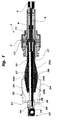
- Figure 1 is a schematic, sectioned, side elevational view of a device according to the invention.
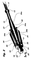
- Figure 2 is a perspective view of some of the elements of the device shown in Figure 1.
- an end portion of a flexible control cable also known as a "push-pull” cable, is generally indicated 1 and comprises, in known manner, a sheath 3 in which an operating cable 5, normally made of metal strands, is mounted for sliding.
- connection unit 7 for connection to a fixing bracket (not shown) anchored to the vehicle on which the control cable is fitted.
- the connection unit 7 includes, in particular, a tubular portion 9 defining an internal spherical seat 11 engaged by the spherical head 13 of an auxiliary tubular body 15 mounted so as to be pivotable relative to the unit 7 to permit limited transverse movements of the end of the operating cable 5.
- the cable 5 has an end rod 17 mounted for sliding in the cavity inside the tubular body 15.
- the rod 17 in turn is fixed by means of a coupling device of known type, for example, of the male-and-female screw type, to a terminal portion 19 of the cable 15, enabling the cable to be connected to a pin of an operating member, for example a gear-shift lever of a motor vehicle (not shown).
- the portion 19 comprises a bush 20 for the anchorage of the opposite end of the rod 17 to the cable 5, a head 22 fixed to the bush defining an internal spherical seat 24 for the engagement of a correspondingly shaped head of the aforementioned pin.
- a shaped element 27 advantageously constituted by an added sleeve-like element which is formed, for example, by the moulding-on of plastics, preferably antifriction, material, and which defines at least one ramp-like or unstable-equilibrium portion for sliding engagement with pressure by a resilient counter member 32 connected axially to the terminal portion 19 of the cable 5.
- the element 27 comprises two opposed ramp-like portions 29a, 29b, each corresponding to one operative position of the cable 5. In the case of the sleeve-like element 27, these ramp-like portions are conical.
- Each ramp-like portion 29a, 29b advantageously extends for a distance at least equal to the travel of the cable 5 relative to the sheath 3, starting from the intermediate rest position.
- the element 27 preferably comprises a flat, stable-equilibrium portion, which can be engaged by the resilient member 32 when the cable 5 adopts the intermediate, rest position between its two opposed operative positions, and which is cylindrical when the element 27 is formed by a sleeve.
- the flat portion 28 is connected to the ramp-like portions 29a and 29b by small curved connecting regions.
- the resilient counter member 32 connected to the terminal portion 19 has a plurality of resilient arms 34, for example, three arms, which surround the element 27 and engage it with radial pressure and with the ability to slide on the outer shaped surface by means of respective curved ends 34a.
- the member 32 is preferably formed in one piece from a metal sheet as a result of a bending operation so that the arms 34 are integral with a collar 36 for connection to the bush 20 of the terminal portion 19.
- the collar 36 has a central axial hole 38, the peripheral rim of which is intended to be fitted in an annular groove 21 of the bush 20.
- the collar has a radial slot 40 so that it can be resiliently opened out slightly so that its rim 38 can be snap-engaged in the groove 21 and can remain therein permanently once the deforming action which brought about its temporary opening-out has ceased.
- the appended drawings show, in particular, a device for stressing a gear engagement cable of a motor-vehicle transmission.
- the radially outer surfaces of the ramp-like or conical portions 29a, 29b are inclined so as to diverge from the flat portion 28 so that, when the ends 34a of the arms of the member 32 are disposed on these conical surfaces, they tend to move axially away from the intermediate flat portion 28.
- the flat portion 28 is disposed in an intermediate position between a pair of ramp-like or conical portions 29a and 29b which have an opposite slope to that shown int the drawings, that is, both converging towards the flat portion 28.
- a taper or inclination to the flat portion of about 6° is preferred, both for gear engagement cables and for gear selection cables.
- this angle could adopt a different value.
- connection portion 19 undergoes a movement substantially along the axis of the cable 5, that is, along the arrow A-B of Figure 2, as a result of the operation of a control lever associated with the vehicle and of the corresponding displacement of a pin with a spherical head connected thereto and engaging the spherical seat 24, and this movement brings about a displacement of the cable 5 relative to the sheath 3, which is normally stationary.
Landscapes
- Engineering & Computer Science (AREA)
- General Engineering & Computer Science (AREA)
- Mechanical Engineering (AREA)
- Health & Medical Sciences (AREA)
- Oral & Maxillofacial Surgery (AREA)
- Gear-Shifting Mechanisms (AREA)
- Flexible Shafts (AREA)
- Insulated Conductors (AREA)
Applications Claiming Priority (2)
| Application Number | Priority Date | Filing Date | Title |
|---|---|---|---|
| ITTO980783 | 1998-09-15 | ||
| IT1998TO000783A IT1304991B1 (it) | 1998-09-15 | 1998-09-15 | Cavo di comando flessibile, particolarmente per cambi di autoveicoli. |
Publications (1)
| Publication Number | Publication Date |
|---|---|
| EP0987453A1 true EP0987453A1 (de) | 2000-03-22 |
Family
ID=11417041
Family Applications (1)
| Application Number | Title | Priority Date | Filing Date |
|---|---|---|---|
| EP99118169A Withdrawn EP0987453A1 (de) | 1998-09-15 | 1999-09-13 | Bowdenzug, insbesondere für die Betätigung von Fahrzeuggetrieben |
Country Status (6)
| Country | Link |
|---|---|
| EP (1) | EP0987453A1 (de) |
| AR (1) | AR020389A1 (de) |
| BR (1) | BR9904615A (de) |
| IT (1) | IT1304991B1 (de) |
| PL (1) | PL335319A1 (de) |
| TR (1) | TR199902292A1 (de) |
Cited By (5)
| Publication number | Priority date | Publication date | Assignee | Title |
|---|---|---|---|---|
| WO2002040878A1 (de) * | 2000-11-20 | 2002-05-23 | Küster Automotive Control Systems GmbH | Schlauchfassung für betätigungszüge |
| EP1312838A3 (de) * | 2001-11-15 | 2005-03-23 | Kia Motors Co., Ltd. | Getriebeschaltkabel für ein automatisches Fahrzeuggetriebe |
| US20110056325A1 (en) * | 2009-09-07 | 2011-03-10 | Hyundai Motor Company | Noise reduction apparatus for shift cable |
| CN106015289A (zh) * | 2016-07-25 | 2016-10-12 | 天津博瑞泰机械零部件有限公司 | 一种换挡拉索套管帽结构 |
| FR3077855A1 (fr) * | 2018-02-15 | 2019-08-16 | Psa Automobiles Sa | Systeme de cable de commande de transmission de vehicule automobile avec manchon d’insonorisation |
Citations (3)
| Publication number | Priority date | Publication date | Assignee | Title |
|---|---|---|---|---|
| WO1992001880A1 (fr) * | 1990-07-23 | 1992-02-06 | Societe Clusienne D'horlogerie Et D'appareils De Precision | Selecteur de man×uvre de transmission manuelle |
| US5265494A (en) * | 1990-03-22 | 1993-11-30 | Pujol Y Tarrago S.A. | Automobile accelerator cable effort incrementing device |
| EP0733814A1 (de) * | 1995-03-17 | 1996-09-25 | FIAT AUTO S.p.A. | Stellvorrichtung für Bowdenzüge |
-
1998
- 1998-09-15 IT IT1998TO000783A patent/IT1304991B1/it active
-
1999
- 1999-09-03 AR ARP990104448A patent/AR020389A1/es unknown
- 1999-09-08 PL PL99335319A patent/PL335319A1/xx not_active Application Discontinuation
- 1999-09-13 BR BR9904615-6A patent/BR9904615A/pt not_active Application Discontinuation
- 1999-09-13 EP EP99118169A patent/EP0987453A1/de not_active Withdrawn
- 1999-09-15 TR TR1999/02292A patent/TR199902292A1/xx unknown
Patent Citations (3)
| Publication number | Priority date | Publication date | Assignee | Title |
|---|---|---|---|---|
| US5265494A (en) * | 1990-03-22 | 1993-11-30 | Pujol Y Tarrago S.A. | Automobile accelerator cable effort incrementing device |
| WO1992001880A1 (fr) * | 1990-07-23 | 1992-02-06 | Societe Clusienne D'horlogerie Et D'appareils De Precision | Selecteur de man×uvre de transmission manuelle |
| EP0733814A1 (de) * | 1995-03-17 | 1996-09-25 | FIAT AUTO S.p.A. | Stellvorrichtung für Bowdenzüge |
Cited By (8)
| Publication number | Priority date | Publication date | Assignee | Title |
|---|---|---|---|---|
| WO2002040878A1 (de) * | 2000-11-20 | 2002-05-23 | Küster Automotive Control Systems GmbH | Schlauchfassung für betätigungszüge |
| EP1312838A3 (de) * | 2001-11-15 | 2005-03-23 | Kia Motors Co., Ltd. | Getriebeschaltkabel für ein automatisches Fahrzeuggetriebe |
| US20110056325A1 (en) * | 2009-09-07 | 2011-03-10 | Hyundai Motor Company | Noise reduction apparatus for shift cable |
| CN102011789A (zh) * | 2009-09-07 | 2011-04-13 | 现代自动车株式会社 | 用于换档拉索的噪音消减装置 |
| US8511201B2 (en) * | 2009-09-07 | 2013-08-20 | Hyundai Motor Company | Noise reduction apparatus for shift cable |
| CN102011789B (zh) * | 2009-09-07 | 2015-01-21 | 现代自动车株式会社 | 用于换档拉索的噪音消减装置 |
| CN106015289A (zh) * | 2016-07-25 | 2016-10-12 | 天津博瑞泰机械零部件有限公司 | 一种换挡拉索套管帽结构 |
| FR3077855A1 (fr) * | 2018-02-15 | 2019-08-16 | Psa Automobiles Sa | Systeme de cable de commande de transmission de vehicule automobile avec manchon d’insonorisation |
Also Published As
| Publication number | Publication date |
|---|---|
| BR9904615A (pt) | 2000-08-08 |
| TR199902292A1 (xx) | 2000-05-22 |
| ITTO980783A1 (it) | 2000-03-15 |
| IT1304991B1 (it) | 2001-04-05 |
| PL335319A1 (en) | 2000-03-27 |
| AR020389A1 (es) | 2002-05-08 |
Similar Documents
| Publication | Publication Date | Title |
|---|---|---|
| EP0589550B1 (de) | Isolierter Schaltgelenkaufbau | |
| US6209414B1 (en) | Cable end structure for pull-cable | |
| EP0148332B1 (de) | Schalthebel | |
| US8418580B2 (en) | Cable assembly | |
| CA2175304C (en) | Core terminal for motion-transmitting remote control assembly | |
| US5862710A (en) | Zero lash joint for a rotating conduit fitting for a remote control cable assembly | |
| WO2010120503A2 (en) | Cable assembly with multi-directional connector | |
| KR100440004B1 (ko) | 자동변속 차량용 트랜스미션 기어 시프트케이블 | |
| US20100275715A1 (en) | Shift cable assembly and connector therefor | |
| WO1998023875A9 (en) | Zero lash joint for a rotating conduit fitting for a remote control cable assembly | |
| EP1479928A1 (de) | Endverbindung eines Steuerkabels mit einem System zur korrekten Montage | |
| EP0987453A1 (de) | Bowdenzug, insbesondere für die Betätigung von Fahrzeuggetrieben | |
| US20030213326A1 (en) | Cable-operated transmission shifters | |
| EP2220386B9 (de) | Verbindungsvorrichtung für ein getriebekabel in einem fahrzeug | |
| US6263757B1 (en) | Cable end structure for pull-cable | |
| EP1630429A1 (de) | Endanschluss eines Mantels eines Betätigungszuges | |
| EP0941412A1 (de) | Anschlussteil für eine betätigungszuganordnung mit dämpfung der vibrationsübertragung | |
| JP2603732Y2 (ja) | 防振ブッシュ | |
| JP4527969B2 (ja) | コントロールケーブルの連結装置 | |
| JPS6344568Y2 (de) | ||
| WO2019087913A1 (ja) | 端末支持装置および端末支持装置を用いたコントロールケーブルアッセンブリ | |
| JPH0545221U (ja) | コントロールケーブルの防振支持装置 | |
| JPS633458Y2 (de) | ||
| KR0134981Y1 (ko) | 자동차의 체인지 컨트롤 케이블용 레버와이어의 꼬임방지용 아이엔드구조 | |
| JPH09226402A (ja) | 自動車用マニュアル変速機の操作レバー装置 |
Legal Events
| Date | Code | Title | Description |
|---|---|---|---|
| PUAI | Public reference made under article 153(3) epc to a published international application that has entered the european phase |
Free format text: ORIGINAL CODE: 0009012 |
|
| AK | Designated contracting states |
Kind code of ref document: A1 Designated state(s): AT BE CH CY DE DK ES FI FR GB GR IE IT LI LU MC NL PT SE |
|
| AX | Request for extension of the european patent |
Free format text: AL;LT;LV;MK;RO;SI |
|
| 17P | Request for examination filed |
Effective date: 20000914 |
|
| AKX | Designation fees paid |
Free format text: AT BE CH CY DE DK ES FI FR GB GR IE IT LI LU MC NL PT SE |
|
| 17Q | First examination report despatched |
Effective date: 20040102 |
|
| STAA | Information on the status of an ep patent application or granted ep patent |
Free format text: STATUS: THE APPLICATION IS DEEMED TO BE WITHDRAWN |
|
| 18D | Application deemed to be withdrawn |
Effective date: 20040713 |