EP0987499A2 - Soupape de déviation et de dérivation - Google Patents
Soupape de déviation et de dérivation Download PDFInfo
- Publication number
- EP0987499A2 EP0987499A2 EP99830452A EP99830452A EP0987499A2 EP 0987499 A2 EP0987499 A2 EP 0987499A2 EP 99830452 A EP99830452 A EP 99830452A EP 99830452 A EP99830452 A EP 99830452A EP 0987499 A2 EP0987499 A2 EP 0987499A2
- Authority
- EP
- European Patent Office
- Prior art keywords
- deviation
- valve
- pass valve
- chamber
- shutter element
- Prior art date
- Legal status (The legal status is an assumption and is not a legal conclusion. Google has not performed a legal analysis and makes no representation as to the accuracy of the status listed.)
- Withdrawn
Links
- 230000009471 action Effects 0.000 claims abstract description 6
- 238000010438 heat treatment Methods 0.000 description 20
- XLYOFNOQVPJJNP-UHFFFAOYSA-N water Substances O XLYOFNOQVPJJNP-UHFFFAOYSA-N 0.000 description 18
- 239000012530 fluid Substances 0.000 description 4
- 239000000463 material Substances 0.000 description 4
- 230000002706 hydrostatic effect Effects 0.000 description 3
- 230000005284 excitation Effects 0.000 description 2
- 239000007788 liquid Substances 0.000 description 2
- 238000012423 maintenance Methods 0.000 description 2
- 238000004519 manufacturing process Methods 0.000 description 2
- 238000002360 preparation method Methods 0.000 description 2
- RYGMFSIKBFXOCR-UHFFFAOYSA-N Copper Chemical compound [Cu] RYGMFSIKBFXOCR-UHFFFAOYSA-N 0.000 description 1
- 230000004913 activation Effects 0.000 description 1
- 239000004411 aluminium Substances 0.000 description 1
- XAGFODPZIPBFFR-UHFFFAOYSA-N aluminium Chemical compound [Al] XAGFODPZIPBFFR-UHFFFAOYSA-N 0.000 description 1
- 229910052782 aluminium Inorganic materials 0.000 description 1
- 230000009286 beneficial effect Effects 0.000 description 1
- 230000008901 benefit Effects 0.000 description 1
- 239000010949 copper Substances 0.000 description 1
- 229910052802 copper Inorganic materials 0.000 description 1
- 230000008878 coupling Effects 0.000 description 1
- 238000010168 coupling process Methods 0.000 description 1
- 238000005859 coupling reaction Methods 0.000 description 1
- 238000004512 die casting Methods 0.000 description 1
- 238000005516 engineering process Methods 0.000 description 1
- 230000005484 gravity Effects 0.000 description 1
- 239000007769 metal material Substances 0.000 description 1
- 238000012986 modification Methods 0.000 description 1
- 230000004048 modification Effects 0.000 description 1
- 238000000465 moulding Methods 0.000 description 1
- 230000009467 reduction Effects 0.000 description 1
- 238000007528 sand casting Methods 0.000 description 1
- 238000007789 sealing Methods 0.000 description 1
- 239000000779 smoke Substances 0.000 description 1
- 238000005406 washing Methods 0.000 description 1
- 238000003466 welding Methods 0.000 description 1
Images

Classifications
-
- F—MECHANICAL ENGINEERING; LIGHTING; HEATING; WEAPONS; BLASTING
- F16—ENGINEERING ELEMENTS AND UNITS; GENERAL MEASURES FOR PRODUCING AND MAINTAINING EFFECTIVE FUNCTIONING OF MACHINES OR INSTALLATIONS; THERMAL INSULATION IN GENERAL
- F16K—VALVES; TAPS; COCKS; ACTUATING-FLOATS; DEVICES FOR VENTING OR AERATING
- F16K11/00—Multiple-way valves, e.g. mixing valves; Pipe fittings incorporating such valves
- F16K11/02—Multiple-way valves, e.g. mixing valves; Pipe fittings incorporating such valves with all movable sealing faces moving as one unit
- F16K11/04—Multiple-way valves, e.g. mixing valves; Pipe fittings incorporating such valves with all movable sealing faces moving as one unit comprising only lift valves
- F16K11/056—Multiple-way valves, e.g. mixing valves; Pipe fittings incorporating such valves with all movable sealing faces moving as one unit comprising only lift valves with ball-shaped valve members
-
- F—MECHANICAL ENGINEERING; LIGHTING; HEATING; WEAPONS; BLASTING
- F24—HEATING; RANGES; VENTILATING
- F24D—DOMESTIC- OR SPACE-HEATING SYSTEMS, e.g. CENTRAL HEATING SYSTEMS; DOMESTIC HOT-WATER SUPPLY SYSTEMS; ELEMENTS OR COMPONENTS THEREFOR
- F24D19/00—Details
- F24D19/10—Arrangement or mounting of control or safety devices
- F24D19/1006—Arrangement or mounting of control or safety devices for water heating systems
- F24D19/1066—Arrangement or mounting of control or safety devices for water heating systems for the combination of central heating and domestic hot water
Definitions
- the present invention relates to a deviation and by-pass valve.
- the invention concerns a three- or more way valve that can operate also as by-pass valve in case the activation conditions occur.
- three- or more way valve is used in order to deviate the path of a tube canalised fluid toward alternative paths, while a by-pass valve is used to open an alternative vent path to the main path, or paths, of the fluid.
- Deviation valves presently available on the market are essentially classified on the basis of the kind of control actuating the motion of the shutter, and can be generically classified as manual deviation valves, hydraulic deviation valves (pressostatic, flowstatic, presso-flowstatic, motorised deviation valves, pneumatic deviation valves and oleodynamic deviation valves.
- By-pass valves presently available on the market can simple on-off valves variously controlled (manual, electric, etc control), used to open an vent alternative path for the fluid or valves suitably created for this function automatically intervening in case special pressure (absolute or differential) or temperature situations occur.
- valves is often used in the heating field.
- manual or automatic on-off valves can determine the complete interruption of water flow creating a thermal overcharge situation for the main exchanger of the boiler, since the means to eliminate heat produced by the burner lack, said situation, in absence of the by-pass valve, ending with the intervention of the safety members suitably provided against overpressures and over - temperatures.
- valve providing a pressostatic by-pass hydraulic valve between inlet tube and return tube of the heating plant, the valve, opening, avoids thermal overcharge maintaining a minimum circulation of water within the boiler allowing to the thermostats provided within the tube at the outlet of the main exchanger, to opportunely sense the increase of the temperature of water flow and to immediately switch off the burner.
- Main object of the present invention is that of providing a valve wherein the by-pass function is englobed in the deviation valve, and, in case special conditions occur requiring the eventual intervention of the by-pass valve, an automatic excitation occurs.
- a deviation and by-pass valve comprising a body valve, within which a chamber is obtained, at least a first and a second inlet opening and an outlet opening from said chamber, a shutter element, provided within said chamber, bucking means, within said chamber, acting in such a way to maintain said shutter element, when in its rest position, in a position to close said second inlet opening, and a linear actuator, acting on said shutter element, against the action of said bucking means, to move the same from its rest position, following an outer control, or a pressure variation within the circuit including the valve.
- said bucking means are comprised of a spring.
- said valve body can be separated or integral with a complex hydraulic group.
- said linear actuator can act on said shutter element by a shaft.
- said linear actuator can be provided with a hydraulic, pneumatic, thermic, electric or electronic control.
- valve according to the invention comprises a chamber 7, within which a shutter 8, preferably a sphere, is provided, on which a bucking spring 6 on one side and a shaft on the other side act, said shaft being coupled with an actuator 11, provided with electric wires 12 and fixing lugs 13.
- valve body 14 Coupling between valve body 14 and the lugs of the actuator 11 is realised by screw 5.
- O-rings 16 are provided, while on the shaft 10, within the portion passing through the valve body 14, a sealing 17 is provided.
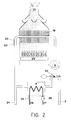
- Mixed boiler shown as an example in figure 2 provides a return tube 2 of primary water from heating system, a pump 9, a main exchanger 19, a burner 20, a smoke discharge 21, a safety thermostat 22 and a heating thermostat 23, and a tube 24 for primary water toward the heating system. Furthermore, a sanitary exchanger 4 is provided, having a sanitary thermostatic 25 and a flow sensor 26, an inlet tube 27 for sanitary cold water and an outlet tube 28 for sanitary hot water.
- valve according to the invention that will be generically indicated in this phase by reference number 30 acts both as deviation valve and as by-pass valve.
- the linear actuator 11 acts on the shutter 8, compressing spring 9, by the shaft 10 to switch the deviation valve closing way 1 of the heating system and opening way 3 toward the sanitary exchanger 4.
- actuator 11 goes back and shutter 8, urged by the spring 9, returns in its rest position, opening again the way 1 of the heating system.
- a pressostatic by-pass valve is provided between the tube to send water and the return tube of the heating system when interruptions of the flow occur in the heating system, valve, opening, avoids the thermic overcharge; in fact, maintenance of a minimum circulation gives the possibility to the thermostats provided on the tube exiting from the main exchanger 19 to opportunely sense the increase of the temperature of water flow and to promptly switch off the burner.
- a pressostatic by-pass valve is a device provided with a calibrated bucking spring normally keeping closed the passage (the shutter).
- the shutter is operated only by the overcoming of a pre-established value of hydrostatic pressure difference.
- the hydrostatic pressure difference is generated by the circulation pump, but until when the circuit of the heating system is opened, at the ends of the by-pass valve, a pressure difference sufficient to open the shutter of the valve is not created. Instead, when the flow in the heating system is almost to be null, the hydrostatic differential pressure threshold is overcome and the by-pass valve opens, thus giving the beneficial effect.
- the shutter 8 is maintained in the rest position (heating mode) by the calibrated spring 9.
- the shutter 8 is urged and compress the spring 9 up to opening the passage toward the sanitary exchanger 4, thus creating a by-pass path.
- the selection control of the way comes from outside by the linear motion actuator 11 maintaining the shutter 8 in a pre-established position in such a way to select the flows to be activated and those to be stopped.
- valve according to the invention maintains always open the so called “rest” paths, while in case of mechanical action alternative paths, so called “excitation” paths, are opened.
- valve like the one according to the invention allows to couple with the same shutter 8 the deviation function and a by-pass valve, being a remarkable advantage for a lower amount of materials necessary to manufacture the valves and a lower use of tubes necessary for the by-pass path with respect to the known solutions.
- valves of the above kind it is possible to realise valves of the above kind to be used in the same or different fields and providing one or more inlets and one or more outlets.
- the movable element of the valve could assume two or more operation positions and thus two or more selectable conditions to switch the flows.
- the by-pass function can be exploited prescinding from the application field, in any situation a design or occasional obstruction of the main circuit served by the deviation valve in the specific application occurs.
- Valve body 14, shutter 8 and all the passive elements of the valve according to the invention realised by the suitable materials on the basis of the specific application, and particularly metallic materials, for example aluminium, or plastic materials, or any other material.
- the most suitable technology will be used (for example die-casting or sand casting, while when copper is used moulding or braze welding) and the most suitable shape will be adopted to satisfy the needing of the use of the valve.
- valve according to the invention in function of the application, it will be necessary to obtain a suitable mechanical resistance to withstand to the stresses induced by liquid inner pressure and by temperature variations, as well as to withstand to the fluid corrosivity and to the corrosivity of the eventual washing liquids for maintenance.
- body 14 of the valve can be separated or integral with a multi-functional hydraulic group.
- actuator 11 it will be chosen on the basis of the features necessary to operate the valve, preferably among those already available on the market, keeping in mind the parameters of maximum stroke, outlet and return speed of the piston, electric supply, force developed by the piston during its exit and return, spatial orientation of the shutter with respect to the gravity force and eventual dynamic actions, foreseen mechanical life as number of cycles.
- actuator 11 could have a hydraulic, pneumatic, thermic, electric, or electronic control.
Landscapes
- Engineering & Computer Science (AREA)
- General Engineering & Computer Science (AREA)
- Mechanical Engineering (AREA)
- Physics & Mathematics (AREA)
- Thermal Sciences (AREA)
- Chemical & Material Sciences (AREA)
- Combustion & Propulsion (AREA)
- Fluid-Driven Valves (AREA)
- Multiple-Way Valves (AREA)
- Servomotors (AREA)
- Superconductors And Manufacturing Methods Therefor (AREA)
- Control Of Motors That Do Not Use Commutators (AREA)
Applications Claiming Priority (2)
| Application Number | Priority Date | Filing Date | Title |
|---|---|---|---|
| ITRM980605 | 1998-09-18 | ||
| IT1998RM000605A IT1302340B1 (it) | 1998-09-18 | 1998-09-18 | Valvola di deviazione e by-pass. |
Publications (2)
| Publication Number | Publication Date |
|---|---|
| EP0987499A2 true EP0987499A2 (fr) | 2000-03-22 |
| EP0987499A3 EP0987499A3 (fr) | 2002-07-17 |
Family
ID=11406140
Family Applications (1)
| Application Number | Title | Priority Date | Filing Date |
|---|---|---|---|
| EP99830452A Withdrawn EP0987499A3 (fr) | 1998-09-18 | 1999-07-16 | Soupape de déviation et de dérivation |
Country Status (2)
| Country | Link |
|---|---|
| EP (1) | EP0987499A3 (fr) |
| IT (1) | IT1302340B1 (fr) |
Cited By (2)
| Publication number | Priority date | Publication date | Assignee | Title |
|---|---|---|---|---|
| EP2613097B1 (fr) | 2012-01-09 | 2016-12-28 | Grundfos Holding A/S | Appareil de chauffage |
| CN116428378A (zh) * | 2023-04-06 | 2023-07-14 | 宁波方太厨具有限公司 | 旁通阀及包含其的热水器 |
Family Cites Families (11)
| Publication number | Priority date | Publication date | Assignee | Title |
|---|---|---|---|---|
| FR1181744A (fr) * | 1957-08-28 | 1959-06-18 | Rech Etudes Production Sarl | électro-valve |
| CH416252A (de) * | 1963-11-27 | 1966-06-30 | Teves Kg Alfred | Aufschlagventil |
| US4171708A (en) * | 1977-04-25 | 1979-10-23 | Lear Siegler, Inc. | Bypass and unloader valve |
| DE2931739C2 (de) * | 1979-08-04 | 1984-07-19 | F.W. Oventrop Arn. Sohn Kg, 5787 Olsberg | Überströmventil zum Einbau in Warmwasserheizungsanlagen |
| JPS5989876A (ja) * | 1982-11-12 | 1984-05-24 | Diesel Kiki Co Ltd | 電磁弁の製造方法 |
| JPS6053289A (ja) * | 1983-09-01 | 1985-03-26 | Diesel Kiki Co Ltd | 両座電磁弁 |
| DE3518978A1 (de) * | 1985-05-25 | 1986-11-27 | Robert Bosch Gmbh, 7000 Stuttgart | Elektromagnetventil |
| AT392137B (de) * | 1989-12-15 | 1991-01-25 | Vaillant Gmbh | Ueberstroemventil |
| IT1240930B (it) * | 1990-03-08 | 1993-12-27 | Fugas Di Matelli L. E Fugazza G. | Valvola a tre vie perfezionata |
| DE4119496A1 (de) * | 1991-06-13 | 1992-12-17 | Drago Dipl Ing Kober | Freilauf-rueckschlagventil, insbesondere fuer fluessiggastanker |
| NL9301212A (nl) * | 1993-06-29 | 1995-01-16 | Jager Beheer Management B V | Omschakelklep. |
-
1998
- 1998-09-18 IT IT1998RM000605A patent/IT1302340B1/it active IP Right Grant
-
1999
- 1999-07-16 EP EP99830452A patent/EP0987499A3/fr not_active Withdrawn
Non-Patent Citations (1)
| Title |
|---|
| None |
Cited By (5)
| Publication number | Priority date | Publication date | Assignee | Title |
|---|---|---|---|---|
| EP2613097B1 (fr) | 2012-01-09 | 2016-12-28 | Grundfos Holding A/S | Appareil de chauffage |
| US10012395B2 (en) | 2012-01-09 | 2018-07-03 | Grundfos Holding A/S | Heating unit |
| EP2613097B2 (fr) † | 2012-01-09 | 2020-11-18 | Grundfos Holding A/S | Appareil de chauffage |
| CN116428378A (zh) * | 2023-04-06 | 2023-07-14 | 宁波方太厨具有限公司 | 旁通阀及包含其的热水器 |
| CN116428378B (zh) * | 2023-04-06 | 2025-08-26 | 宁波方太厨具有限公司 | 旁通阀及包含其的热水器 |
Also Published As
| Publication number | Publication date |
|---|---|
| EP0987499A3 (fr) | 2002-07-17 |
| IT1302340B1 (it) | 2000-09-05 |
| ITRM980605A1 (it) | 2000-03-18 |
Similar Documents
| Publication | Publication Date | Title |
|---|---|---|
| EP0614033B1 (fr) | Soupape de conduite à trois voies responsable à la chaleur avec commande par alliage à mémoire | |
| US4767052A (en) | Thermostatically self-regulating mixing valve | |
| EP1362214B1 (fr) | Echangeur thermique a plaques | |
| US5323803A (en) | Instant hot water device | |
| EP0797057B1 (fr) | Ensemble de soupape avec pompe intégrée pour chaudière mixte chauffage / eau sanitaire | |
| EP2244151A2 (fr) | Soupape de commande électrique | |
| EP0568122B1 (fr) | Arrangement de soupape prévu pour installations de chauffage ainsi que pour chauffe-eau domestique | |
| EP2280205B1 (fr) | Soupape de dériveur et système de chauffage | |
| US3332440A (en) | Sequentially-actuated multiplefunction control valve | |
| EP0987499A2 (fr) | Soupape de déviation et de dérivation | |
| US4738395A (en) | Fluid flow rate detector and system | |
| EP0466010B1 (fr) | Dispositif de soupape pour installation de chauffage | |
| US6354813B1 (en) | Hydraulically activated three-way-valve | |
| WO2006027368A1 (fr) | Echangeur thermique muni d'une soupape a temperature controle | |
| CN101070916A (zh) | 一种双金属温度控制阀门 | |
| US4556168A (en) | Rapid response water heating and delivery system | |
| GB2416823A (en) | Mixing valve | |
| US8505619B2 (en) | Heat exchanger with temperature-controlled valve | |
| CA3057194A1 (fr) | Chauffe-eau electrique sans reservoir | |
| JPS6190620A (ja) | コ−ヒ−メ−カ− | |
| EP1774210A1 (fr) | Melangeur | |
| US20090065722A1 (en) | Pressure control valve | |
| US3273797A (en) | Air conditioner valve | |
| CN208871036U (zh) | 循环温控洗浴阀及节能节水型热水器热水循环系统 | |
| US3179337A (en) | Heating and cooling control valves |
Legal Events
| Date | Code | Title | Description |
|---|---|---|---|
| PUAI | Public reference made under article 153(3) epc to a published international application that has entered the european phase |
Free format text: ORIGINAL CODE: 0009012 |
|
| AK | Designated contracting states |
Kind code of ref document: A2 Designated state(s): AT BE CH CY DE DK ES FI FR GB GR IE IT LI LU MC NL PT SE |
|
| AX | Request for extension of the european patent |
Free format text: AL;LT;LV;MK;RO;SI |
|
| PUAL | Search report despatched |
Free format text: ORIGINAL CODE: 0009013 |
|
| AK | Designated contracting states |
Kind code of ref document: A3 Designated state(s): AT BE CH CY DE DK ES FI FR GB GR IE IT LI LU MC NL PT SE |
|
| AX | Request for extension of the european patent |
Free format text: AL;LT;LV;MK;RO;SI |
|
| RIC1 | Information provided on ipc code assigned before grant |
Free format text: 7F 24D 19/10 A, 7F 16K 31/06 B |
|
| AKX | Designation fees paid | ||
| REG | Reference to a national code |
Ref country code: DE Ref legal event code: 8566 |
|
| STAA | Information on the status of an ep patent application or granted ep patent |
Free format text: STATUS: THE APPLICATION IS DEEMED TO BE WITHDRAWN |
|
| 18D | Application deemed to be withdrawn |
Effective date: 20030118 |