EP0987515A2 - Aufsatzelement und Vorrichtung zur Positionsbestimmung oder Ausmessung eines Loches oder eines Bolzens - Google Patents
Aufsatzelement und Vorrichtung zur Positionsbestimmung oder Ausmessung eines Loches oder eines Bolzens Download PDFInfo
- Publication number
- EP0987515A2 EP0987515A2 EP99113893A EP99113893A EP0987515A2 EP 0987515 A2 EP0987515 A2 EP 0987515A2 EP 99113893 A EP99113893 A EP 99113893A EP 99113893 A EP99113893 A EP 99113893A EP 0987515 A2 EP0987515 A2 EP 0987515A2
- Authority
- EP
- European Patent Office
- Prior art keywords
- attachment element
- component
- bolt
- hole
- internal thread
- Prior art date
- Legal status (The legal status is an assumption and is not a legal conclusion. Google has not performed a legal analysis and makes no representation as to the accuracy of the status listed.)
- Ceased
Links
Images

Classifications
-
- G—PHYSICS
- G01—MEASURING; TESTING
- G01B—MEASURING LENGTH, THICKNESS OR SIMILAR LINEAR DIMENSIONS; MEASURING ANGLES; MEASURING AREAS; MEASURING IRREGULARITIES OF SURFACES OR CONTOURS
- G01B5/00—Measuring arrangements characterised by the use of mechanical techniques
- G01B5/0025—Measuring of vehicle parts
-
- G—PHYSICS
- G01—MEASURING; TESTING
- G01B—MEASURING LENGTH, THICKNESS OR SIMILAR LINEAR DIMENSIONS; MEASURING ANGLES; MEASURING AREAS; MEASURING IRREGULARITIES OF SURFACES OR CONTOURS
- G01B5/00—Measuring arrangements characterised by the use of mechanical techniques
- G01B5/004—Measuring arrangements characterised by the use of mechanical techniques for measuring coordinates of points
Definitions
- the present invention relates to an attachment element and a Device for determining the position or measuring a hole or a bolt according to the preamble of the claim 1, or according to the preamble of claim 8 and the preamble of patent claim 10.
- DE-PS 936 895 describes a device for measuring distances known to an object, which in a hole of the measuring object is introduced.
- the device exists from two separate parts, namely a shaft for fitting into the hole of the object and a part which is in a Sphere of a certain radius of curvature ends. This ball is positionable in such a way that it serves as a reference point with regard to the The center of the hole serves.
- a disadvantage of this device is considered that only in the hole to be measured a pin is inserted which is inside the hole is not completely fixable. This leads to the measurement to measurement errors.
- From DE-PS 733 370 is a device for measuring distances of connection points, especially not directly measurable Points known as ball centers, which are from a main scale with longitudinally adjustable slide bodies and in these transverse to Main scale displaceable measuring elements there. This is proportionate large-scale facility is for example for measurements unsuitable in inaccessible places.
- German utility model G 91 06 101 discloses a precision measuring stick, which by inserting a mandrel into an opening allows a measurement of the diameter of the opening. The exact positioning of the opening is not the subject of teaching described in this document.
- the object of the present invention is to create a device with a precise and uncomplicated position determination or measuring holes or welding or threaded bolts a component is possible in a simple manner.
- attachment element or devices created with which the exact positioning of holes or recesses or welding or threaded bolts, for example on a body of a motor vehicle, in simple Way is feasible.
- the attachment elements according to the invention are flexible for both measuring holes as well as threaded bolts. Also measurements on inaccessible places, for example the floor panel of a Vehicle body are easily possible.
- the invention Attachment element is characterized by low manufacturing costs as well as quick assembly and disassembly. Adjustments to different thread pitches can be made in simple way by appropriate design of the internal thread of the attachment element can be made.
- the attachment element and the fixing screw are from opposite Sides of the hole applied to this or in this introduced and screwed together. This is one precise clamping fixation of the device or the attachment element achievable on the component.
- a locating bush which the outer diameter of the bolt corresponds to the internal thread of the attachment element screwable.
- the assembly and disassembly takes place by plugging and unplugging onto or from the measurement Bolt.
- a magnetic one proves to be particularly advantageous here
- the Attachment element can be knurled, whereby a particularly simple disassembly of the attachment element is possible.
- the change of the fixing bush is for example using a screwdriver feasible.
- Hardening proves to be particularly advantageous the fixing bushing, so that wear of the fixing bushing inner diameter can be avoided, creating a high Durability is guaranteed.
- Attachment element this has a substantially hemispherical or part-spherical outer contour or shape.
- the Measurement such hemispherical or partially spherical elements turns out to be particularly simple and inexpensive. For example position of a bolt to be measured deviate from its target position by up to 5 mm in all directions, without a CNC series measurement process when measuring the ball is interrupted with a collision. The procedural steps in the CNC process a sphere measurement are always the same.
- the element Sphere can always be mirrored when programming, provided the position of the bolts relative to one another in the slant is not serious differ from each other. Especially when measuring spherical shapes of this type prove that the attachment element is firmly seated as beneficial.
- the inventive Attachment element also angular, in particular as a hexagon or Octagonal, can be formed.
- Preferred materials for the Attachment elements are plastics, metals or other suitable Materials.
- the top element expediently has on its underside a support ring. This ensures that Attachment element even if the component surface is uneven near holes or bolts (for example, conditionally by welding spatter, punch burrs or bolt feet) Component can rest.
- a support ring can, for example a ring thickness of 2mm with an inner ring diameter of 17mm.
- the attachment element a chamfer on its lower edge.
- Such a bevel which preferably has an angle of approximately 45 ° an injury-free screwing and unscrewing as well as a good handling of the attachment element according to the invention by a User.
- the internal thread is asymmetrical with respect to the attachment element is arranged.
- this measure it is possible Holes or bolts on inaccessible edge areas or in Measure the runout of curves of a component.
- a hemispherical or partially spherical outer contour of the Attachment element is such an asymmetrical design for example by milling on one or both sides of the attachment element can be reached.
- the internal thread is designed as a through thread. This makes it possible to use bolts or screws of any kind Length using the attachment element according to the invention to measure.
- the attachment element expediently has an insert, in particular an annular insert, from a magnetic Material on.
- an insert in particular an annular insert, from a magnetic Material on.
- the device for determining the position or measurement of a hole has the fixing screw a tapered section.
- Means such a conical section is special secure and precise positioning of the fixing screw in one Hole possible.
- the attachment element 1 shown in FIG. 1 essentially has one hemispherical contour. In the middle of the Attachment element 1 is designed with an internal thread 2 Recess provided.
- the attachment element 1 also has its underside 5 has a support ring 3.
- the attachment element 1 can also be present of bumps 10 (see Fig. 2, in the example a welding sprayer 10 is shown) perpendicular to a component be positioned.
- the bottom edge area of the attachment element 1 is formed with a chamfer 4, which is the simple one and safe handling of the attachment element is used.
- the bevel 4 preferably has an angle of 45 ° with respect to the underside 5 of the attachment element 1.
- attachment element 1 in a device for measuring or determining position a hole 20 in a component 21, in particular one Body component of a motor vehicle will be explained.
- the attachment element is analogous to the measurement or Determining the position of a bolt provided on the component 21 22, as shown on the right in FIG. 2, can be used.
- the attachment element 1 acts with a grub screw or Fixing screw 11 together.
- This fixing screw 11 is on hers formed upper end with a thread 12, which with the internal thread 2 can be screwed. On the thread 12 is followed by a conical section 13.
- the lower area 14 of the fixing screw 11 is knurled, whereby handling is easier.
- the attachment element 1 and the fixing screw 11 are of opposite Pages brought up to the hole 20.
- the attachment element 1 on a first side 21a of the component 21 upset.
- the attachment element 1 is in this case the hole 20 surrounding surface of the component 21 can be placed.
- the fixing screw 11 is viewed from a second side 21b of the component 21 in the hole 20 inserted.
- thread 12 and internal thread 2 screwed together by clamping component 21.
- the conical section 13 acts the underside of the hole 20 or the component 21 and thus ensures for optimal centering of the fixing screw 11 in the hole 20.
- After screwing the components 1, 11 together is one positionally accurate fixation of the attachment element 1 with respect to the Hole 20 guaranteed.
- the measurement of the attachment element 1 for determining the position of the hole 20 takes place in a manner known per se Wise .
- the attachment element 1 is formed with a flattened area 1a, whereby the internal thread 2 is asymmetrical with respect to the attachment element 1 is arranged. With such a configuration it is possible to make holes in the vicinity of edge areas 21c of a component 21 to be measured.
- the attachment element 1 is designed without a support ring. It is also possible to use the embodiment 3 with chamfers (not shown here) or support rings, as shown for example in Fig. 1 are training. Furthermore, the one with the attachment element 1 cooperating fixing screw 11 only partially shown.
- the flattened area is, for example, by milling the Attachment element 1 can be produced.
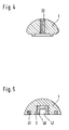
- the attachment element 1 shown in FIG. 4 has an as Through thread 32 formed internal thread. With a such internal thread, it is possible to use bolts or fixing screw threaded sections to measure any length.
- the attachment element 1 is here also with an internal thread 2 educated.
- a fixing bushing with an external thread 40 can be screwed into the internal thread 2.
- the fixing bush 40 has a recess 42, the shape of which one measuring bolt (not shown) is adapted.
- the fixing bush 40 can also be formed with a continuous recess be, and for example with a through hole of the Top element, as shown in Fig. 4, cooperate.
- the attachment element 1 has a magnet ring magnetic insert 41.
- the fixing bushes 40 is an adaptation to in a simple manner different bolt diameters or bolt shapes possible.
- Means a (not shown) slot in the fixing bush 40 for example using a screwdriver, the fixing bushing can be replaced in a simple manner. 5 is both on smooth bolts (Welding studs) and threaded studs can be pushed on.
- the illustrated Device can also with (not shown) Support rings, chamfers or knurls should be formed.
Landscapes
- Physics & Mathematics (AREA)
- General Physics & Mathematics (AREA)
- Connection Of Plates (AREA)
- Length Measuring Devices With Unspecified Measuring Means (AREA)
Abstract
Description
- Fig. 1
- eine seitliche Schnittansicht einer ersten bevorzugten Ausführungsform des erfindungsgemäßen Aufsatzelements,
- Fig. 2
- eine explodierte seitliche Schnittansicht einer bevorzugten Ausführungsform der erfindungsgemäßen Vorrichtung zur Ausmessung bzw. Positionsbestimmung eines Loches,
- Fig. 3
- eine seitliche Schnittansicht einer weiteren bevorzugten Ausführungsform des Aufsatzelements bzw. der Vorrichtung in montierter Stellung,
- Fig. 4
- eine seitliche Schnittansicht einer weiteren bevorzugten Ausführungsform des erfindungsgemäßen Aufsatzelements, und
- Fig. 5
- eine seitliche Schnittansicht einer bevorzugten Ausführugnsform einer erfindungsgemäßen Vorrichtung zur Positionsbestimmung oder Ausmessung eines Bolzens.
Claims (10)
- Aufsatzelement zur Positionsbestimmung oder Ausmessung eines an einem Bauteil ausgebildeten Loches oder Bolzens, insbesondere eines Schweißbolzens oder Gewindebolzens, welches auf einer ersten Seite des Bauteils auf eine das Loch oder den Bolzen umgebende Bauteiloberfläche aufbringbar ist,
dadurch gekennzeichnet,
daß das Aufsatzelement (1) ein mit einer von einer zweiten Seite des Bauteils in das Loch einbringbaren Fixierschraube zur Fixierung des Aufsatzelementes (1) an dem Bauteil unter Einklemmung des Bauteils zwischen dem Aufsatzelement (1) und der Fixierschraube bzw. mit dem Bolzen oder einer dem Außendurchmesser des Bolzens angepaßten Fixierbuchse (40) verschraubbares Innengewinde (2, 32) aufweist. - Aufsatzelement nach Anspruch 1, dadurch gekennzeichnet, daß es eine im wesentlichen halbkugelförmige oder teilkugelförmige Außenkontur aufweist.
- Aufsatzelement nach einem der Ansprüche 1 oder 2, dadurch gekennzeichnet, daß es an seiner Unterseite (5) einen Auflagering (3) aufweist.
- Aufsatzelement nach einem der vorstehenden Ansprüche, dadurch gekennzeichnet, daß es an seiner Unterkante eine Fase (4) aufweist.
- Aufsatzelement nach einem der vorstehenden Ansprüche, dadurch gekennzeichnet, daß das Innengewinde (2, 32) bezüglich des Aufsatzelements (1) asymmetrisch angeordnet ist.
- Aufsatzelement nach einem der vorstehenden Ansprüche, dadurch gekennzeichnet, daß das Innengewinde als Durchgangsgewinde (32) ausgebildet ist.
- Aufsatzelement nach einem der vorstehenden Ansprüche, dadurch gekennzeichnet, daß sie einen Einsatz (41), insbesondere einen ringförmigen Einsatz, aus einem magnetischen Material aufweist.
- Vorrichtung zur Positionsbestimmung oder Ausmessung eines Loches in einem Bauteil, insbesondere einem Karosserieteil eines Kraftfahrzeugs, gekennzeichnet durch ein Aufsatzelement (1) gemäß einem der Ansprüche 1 bis 7 sowie eine mit dem Innengewinde (2, 32) des Aufsatzelements (1) zusammenwirkende Fixierschraube (11), wobei das Aufsatzelement (1) auf einer ersten Seite des Bauteils auf eine das Loch umgebende Bauteiloberfläche aufbringbar, und die Fixierschraube (11) von einer zweiten Seite des Bauteils zur Fixierung des Aufsatzelementes (1) an dem Bauteil unter Einklemmung des Bauteils zwischen dem Aufsatzelement (1) und der Fixierschraube (11) in das Loch einbringbar und mit dem Innengewinde (2, 32) des Aufsatzelementes (1) verschraubbar ist.
- Vorrichtung nach Anspruch 8, dadurch gekennzeichnet, daß die Fixierschraube (11) einen konisch zulaufenden Abschnitt (13) aufweist.
- Vorrichtung zur Positionsbestimmung oder Ausmessung eines Bolzens an einem Bauteil, insbesondere einem Karosserieteil eines Kraftfahrzeugs, gekennzeichnet durch ein Aufsatzelement (1) gemäß einem der Ansprüche 1 bis 7 sowie eine mit dem Innengewinde (2) des Aufsatzelements verschraubbaren Fixierbuchse (40), welche eine der Form bzw. dem Durchmesser des Bolzens entsprechende Ausnehmung aufweist.
Applications Claiming Priority (2)
| Application Number | Priority Date | Filing Date | Title |
|---|---|---|---|
| DE19842630 | 1998-09-17 | ||
| DE19842630A DE19842630A1 (de) | 1998-09-17 | 1998-09-17 | Aufsatzelement und Vorrichtung zur Positionsbestimmung oder Ausmessung eines Loches oder eines Bolzens |
Publications (2)
| Publication Number | Publication Date |
|---|---|
| EP0987515A2 true EP0987515A2 (de) | 2000-03-22 |
| EP0987515A3 EP0987515A3 (de) | 2001-09-19 |
Family
ID=7881302
Family Applications (1)
| Application Number | Title | Priority Date | Filing Date |
|---|---|---|---|
| EP99113893A Ceased EP0987515A3 (de) | 1998-09-17 | 1999-07-16 | Aufsatzelement und Vorrichtung zur Positionsbestimmung oder Ausmessung eines Loches oder eines Bolzens |
Country Status (3)
| Country | Link |
|---|---|
| US (1) | US6427356B1 (de) |
| EP (1) | EP0987515A3 (de) |
| DE (1) | DE19842630A1 (de) |
Families Citing this family (14)
| Publication number | Priority date | Publication date | Assignee | Title |
|---|---|---|---|---|
| US6582711B1 (en) * | 1997-01-09 | 2003-06-24 | 3M Innovative Properties Company | Hydroalcoholic compositions thickened using polymers |
| US7329076B2 (en) * | 2004-12-01 | 2008-02-12 | Honeywell International Inc. | Hole location gauges and methods |
| US7810246B2 (en) * | 2008-08-28 | 2010-10-12 | Falk PLI Engineering and Surveying, Inc. | Bolt as-builter survey cone |
| US7999243B2 (en) * | 2008-09-22 | 2011-08-16 | GM Global Technology Operations LLC | Apparatus and method for determining a dimensional characteristic of an installed weld fastener |
| CN102735139A (zh) * | 2012-06-18 | 2012-10-17 | 上海卫星工程研究所 | 一种用于检测螺孔相关尺寸的辅助量具 |
| US9151587B2 (en) * | 2013-11-11 | 2015-10-06 | General Electric Company | Bucket tip shroud measurement fixture and method of measuring bucket tip shroud orientation |
| US9733057B2 (en) * | 2015-09-25 | 2017-08-15 | The Boeing Company | Blind hole location tool |
| US9746314B2 (en) * | 2015-10-26 | 2017-08-29 | Micro Surface Engineering, Inc. | Scanning laser target sphere with internal concentric mount |
| KR102042481B1 (ko) * | 2017-12-11 | 2019-11-11 | (주)태현 | 나사검사장치 |
| US10549395B2 (en) * | 2018-01-11 | 2020-02-04 | Rolls-Royce Corporation | Hand tool for self aligned placement of surface mounted tooling element |
| FR3077874B1 (fr) * | 2018-02-14 | 2021-05-28 | Psa Automobiles Sa | Procede de mesure de position d’un debouche d’au moins un evidement sur une piece |
| US10279397B1 (en) * | 2018-06-22 | 2019-05-07 | Symtech Industrial, Llc | Blind hole locating systems, devices, and methods |
| US10982943B1 (en) * | 2018-11-05 | 2021-04-20 | United States Of America As Represented By The Secretary Of The Air Force | Countersink go/no-go gauge for a rivet |
| CN112504057A (zh) * | 2020-12-03 | 2021-03-16 | 安徽江淮汽车集团股份有限公司 | 一种检测工装 |
Family Cites Families (20)
| Publication number | Priority date | Publication date | Assignee | Title |
|---|---|---|---|---|
| US1032831A (en) * | 1911-04-08 | 1912-07-16 | John G Hodgson | Nut-lock. |
| US2063181A (en) * | 1930-11-22 | 1936-12-08 | Miller Glenmore | Self-locking nut washer |
| DE733370C (de) * | 1937-12-04 | 1943-03-25 | Messerschmitt Boelkow Blohm | Einrichtung zur Messung der Abstaende von Anschlusspunkten, insbesondere nicht direkt messbarer Punkte, wie Kugelmitten u. dgl., in zwei verschiedenen, vorzugsweise senkrecht zueinander stehenden Richtungen |
| US2419134A (en) * | 1944-06-17 | 1947-04-15 | Hall Nelson | Locator utilizable in forming metal articles |
| US2679692A (en) * | 1953-04-06 | 1954-06-01 | Eugene D Fortner | Port gauge |
| GB728426A (en) * | 1953-07-29 | 1955-04-20 | Notsa Engineering Co Ltd | Improvements relating to tooling pins |
| DE936895C (de) * | 1953-07-29 | 1955-12-22 | James Lowther | Verfahren und Vorrichtung zur Messung von Abstaenden |
| NL215306A (de) * | 1956-03-16 | |||
| US3026621A (en) * | 1960-02-19 | 1962-03-27 | Joseph S Papps | Hole position gauging means |
| US4539753A (en) * | 1983-04-18 | 1985-09-10 | Fitzpatrick John F | Inspection tool |
| US4907929A (en) * | 1986-11-25 | 1990-03-13 | Johnston Jr Raymond B | Bolt and nut cover |
| JPS6458530A (en) * | 1987-08-31 | 1989-03-06 | Toyoda Gosei Kk | Tapping prepared hole structure of blow molded product |
| US5122019A (en) * | 1991-01-03 | 1992-06-16 | Douglas Unger | Wall covering installation system |
| DE9106101U1 (de) * | 1991-05-17 | 1991-08-29 | Müller, Bruno, 2730 Zeven | Präzisionsmeßsatz |
| US5179788A (en) * | 1992-05-11 | 1993-01-19 | Jadach Albert A | Locating plug for the centerlines of holes |
| US5272927A (en) * | 1992-06-03 | 1993-12-28 | Carlen Controls, Inc. | Anti-backlash spline coupling for use in a position measuring system |
| FR2697461B1 (fr) * | 1992-11-05 | 1995-01-06 | Norelem | Eléments métalliques modulaires perfectionnés pour le support de pièces cylindriques et coniques dans des montages d'usinage et de contrôle. |
| US5678703A (en) * | 1995-07-31 | 1997-10-21 | Sawyer; Gerald F. | Finial adapter for curtain rods |
| US5702214A (en) * | 1996-11-07 | 1997-12-30 | Avibank Mfg., Inc. | Non-removable structural fastener assembly |
| JP3403626B2 (ja) * | 1997-12-26 | 2003-05-06 | 矢崎総業株式会社 | ボルト用クランプ |
-
1998
- 1998-09-17 DE DE19842630A patent/DE19842630A1/de not_active Withdrawn
-
1999
- 1999-07-16 EP EP99113893A patent/EP0987515A3/de not_active Ceased
- 1999-09-17 US US09/397,734 patent/US6427356B1/en not_active Expired - Fee Related
Also Published As
| Publication number | Publication date |
|---|---|
| DE19842630A1 (de) | 2000-04-20 |
| US6427356B1 (en) | 2002-08-06 |
| EP0987515A3 (de) | 2001-09-19 |
Similar Documents
| Publication | Publication Date | Title |
|---|---|---|
| DE3248547C2 (de) | ||
| DE19842630A1 (de) | Aufsatzelement und Vorrichtung zur Positionsbestimmung oder Ausmessung eines Loches oder eines Bolzens | |
| DE102006009422A1 (de) | Vorrichtung zur Überprüfung der Genauigkeit einer von einer Arbeitsspindel auszuführenden Kreisbahn | |
| DE10239694A1 (de) | Verfahren zur Kalibrierung eines Fräsers | |
| DE3727857C2 (de) | ||
| DE202008005154U1 (de) | Vorrichtung zur Überprüfung der Maß-, Form- und Lagetoleranzen von Konturen an Werkstücken | |
| DE20116188U1 (de) | Meßgerät zum Feststellen der Maßgenauigkeit von kegeligen Bohrungen | |
| DE3706123A1 (de) | Vorrichtung zur verbindung eines schaftes mit einem anderen teil, insbesondere zur halterung von einen schaft aufweisenden werkzeugen oder werkstuecken | |
| EP1794538B1 (de) | Messschraube mit nicht drehendem messbolzen | |
| DE2632922A1 (de) | Anwendung einer positioniereinrichtung | |
| DE19820340C2 (de) | Vorrichtung zur Positionsbestimmung oder Ausmessung eines Loches | |
| DE2849010A1 (de) | Messgeraet zur feststellung der massgenauigkeit von kegeligen bohrungen | |
| DE112004000871B4 (de) | Vorrichtung und Verfahren zum Vermessen der Geometrie einer Radachse eines Kraftfahrzeuges | |
| DE19951588C2 (de) | Vorrichtung zur Positionsbestimmung oder Ausmessung eines Loches | |
| DE3131478A1 (de) | Vorrichtung zur verbindung zweier um eine gemeinsame achse rotierender werkzeugteile | |
| DE10238650B4 (de) | Winkeleinstellvorrichtung | |
| DE19534338C1 (de) | Feinmeßgerät mit auswechselbaren Meßeinsätzen | |
| DE2743163C2 (de) | Einstellanordnung | |
| DE733370C (de) | Einrichtung zur Messung der Abstaende von Anschlusspunkten, insbesondere nicht direkt messbarer Punkte, wie Kugelmitten u. dgl., in zwei verschiedenen, vorzugsweise senkrecht zueinander stehenden Richtungen | |
| EP1938665B1 (de) | Vorrichtung und verfahren zum vermessen mindestens eines konischen gewindes | |
| DE2034571A1 (de) | Winkelmeßgerat | |
| DE1714089U (de) | Vorrichtung zur messung von abstaenden. | |
| DE4004486C2 (de) | ||
| CH672181A5 (de) | ||
| DE69920385T2 (de) | Vorrichtung zur Neigungseinstellung von zwei mechanischen Teilen und Herstellungsverfahren der Vorrichtung |
Legal Events
| Date | Code | Title | Description |
|---|---|---|---|
| PUAI | Public reference made under article 153(3) epc to a published international application that has entered the european phase |
Free format text: ORIGINAL CODE: 0009012 |
|
| AK | Designated contracting states |
Kind code of ref document: A2 Designated state(s): AT BE CH CY DE DK ES FI FR GB GR IE IT LI LU MC NL PT SE |
|
| AX | Request for extension of the european patent |
Free format text: AL;LT;LV;MK;RO;SI |
|
| PUAL | Search report despatched |
Free format text: ORIGINAL CODE: 0009013 |
|
| AK | Designated contracting states |
Kind code of ref document: A3 Designated state(s): AT BE CH CY DE DK ES FI FR GB GR IE IT LI LU MC NL PT SE |
|
| AX | Request for extension of the european patent |
Free format text: AL;LT;LV;MK;RO;SI |
|
| 17P | Request for examination filed |
Effective date: 20010829 |
|
| AKX | Designation fees paid |
Free format text: AT BE CH CY DE DK ES FI FR GB GR IE IT LI LU MC NL PT SE |
|
| RAP1 | Party data changed (applicant data changed or rights of an application transferred) |
Owner name: DAIMLERCHRYSLER AG |
|
| 17Q | First examination report despatched |
Effective date: 20071015 |
|
| RAP1 | Party data changed (applicant data changed or rights of an application transferred) |
Owner name: DAIMLER AG |
|
| STAA | Information on the status of an ep patent application or granted ep patent |
Free format text: STATUS: THE APPLICATION HAS BEEN REFUSED |
|
| 18R | Application refused |
Effective date: 20080515 |