EP0987526A2 - Anpassbarer Gaszähler - Google Patents
Anpassbarer Gaszähler Download PDFInfo
- Publication number
- EP0987526A2 EP0987526A2 EP99117865A EP99117865A EP0987526A2 EP 0987526 A2 EP0987526 A2 EP 0987526A2 EP 99117865 A EP99117865 A EP 99117865A EP 99117865 A EP99117865 A EP 99117865A EP 0987526 A2 EP0987526 A2 EP 0987526A2
- Authority
- EP
- European Patent Office
- Prior art keywords
- gas
- box
- inlet
- outlet
- measuring means
- Prior art date
- Legal status (The legal status is an assumption and is not a legal conclusion. Google has not performed a legal analysis and makes no representation as to the accuracy of the status listed.)
- Withdrawn
Links
Images


Classifications
-
- G—PHYSICS
- G01—MEASURING; TESTING
- G01F—MEASURING VOLUME, VOLUME FLOW, MASS FLOW OR LIQUID LEVEL; METERING BY VOLUME
- G01F15/00—Details of, or accessories for, apparatus of groups G01F1/00 - G01F13/00 insofar as such details or appliances are not adapted to particular types of such apparatus
- G01F15/18—Supports or connecting means for meters
- G01F15/185—Connecting means, e.g. bypass conduits
-
- G—PHYSICS
- G01—MEASURING; TESTING
- G01F—MEASURING VOLUME, VOLUME FLOW, MASS FLOW OR LIQUID LEVEL; METERING BY VOLUME
- G01F15/00—Details of, or accessories for, apparatus of groups G01F1/00 - G01F13/00 insofar as such details or appliances are not adapted to particular types of such apparatus
- G01F15/12—Cleaning arrangements; Filters
- G01F15/125—Filters
-
- G—PHYSICS
- G01—MEASURING; TESTING
- G01F—MEASURING VOLUME, VOLUME FLOW, MASS FLOW OR LIQUID LEVEL; METERING BY VOLUME
- G01F15/00—Details of, or accessories for, apparatus of groups G01F1/00 - G01F13/00 insofar as such details or appliances are not adapted to particular types of such apparatus
- G01F15/14—Casings, e.g. of special material
-
- G—PHYSICS
- G01—MEASURING; TESTING
- G01F—MEASURING VOLUME, VOLUME FLOW, MASS FLOW OR LIQUID LEVEL; METERING BY VOLUME
- G01F15/00—Details of, or accessories for, apparatus of groups G01F1/00 - G01F13/00 insofar as such details or appliances are not adapted to particular types of such apparatus
- G01F15/18—Supports or connecting means for meters
Definitions
- the present invention relates to the field of gas meters. More specifically, the present invention relates to an adaptable case for gas meters.
- apparatus for measuring gas flow comprising at least one gas measuring means, and a box, wherein said at least one gas measuring means is disposed within said box and wherein said box has a gas inlet means and a gas outlet means and is divided into an inlet chamber and an outlet chamber by a dividing plate to which said at least one gas measuring means to measure gas flow for a plurality of gas pipe configurations and with plurality of gas pipe fining requirements.
- the present invention offers the technical advantage of allowing a single type of gas meter to be used in a variety of configurations and with a variety of gas pipe fittings as found in different countries. Furthermore the present invention allows for a large volume of gas in the inlet chamber, thus reducing the gas flow rate within the gas meter. This provided the technical advantage of increasing the amount of dust which settles out of the gas prior to filtration in the inlet chamber which may otherwise adversely affect the accuracy of current gas meters.
- the present invention allows for a reduced pressure differential between the inlet and outlet of the gas measuring means.
- relatively large pressure differentials can adversely affect the accuracy of the gas measuring means.
- the present invention improves the accuracy of current gas measuring systems.
- FIG 3 a first embodiment 30 of the present invention is shown with the gas inlet means 2 and gas outlet means 4 arranged in a conventional style on the top 5 of box 6.
- the electronics module 7 comprises a display 13 and an opto port 14 for the purposes of displaying meter information and communication respectively.
- the gas measuring means is located inside box 6 and thus is not shown.
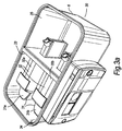
- FIG 3a in which parts also appearing in figure 3 bear identical numerical designation, shows essentially the same embodiment 30 as shown in Figure 3, but with top 5 of box 6 removed.
- a dividing wall 33 divides box 6 into two chambers; a gas inlet chamber 34 and a gas outlet chamber 35. At least one of gas measuring devices, 31a and 31b is disposed in the gas inlet chamber and are substantially attached, fixed or otherwise secured to dividing wall 33.
- a pair of gas filter devices 32a, 32b are disposed in the gas inlet chamber 34.
- the gas filter devices may be an integral part of the gas measuring device.
- the system as shown in figure 3 and 3a operates essentially as follows. Gas flows into gas meter system 30 via a gas inlet means 2 and enters gas inlet chamber 34. The gas enters the gas filter devices 32a, 32b then passes through the gas measuring devices 31a, 31b and on through the dividing wall 33 and into the gas outlet chamber 34 before leaving the system via gas outlet means 4.
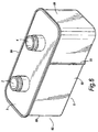
- FIG 4 a further embodiment of the present invention is shown in which a concentric gas inlet/outlet arrangement 40 is employed.
- a dividing wall 43 separates box 6 into two chambers, a gas inlet chamber 44 and a gas outlet chamber 45.
- Gas measuring devices, 41 are disposed on the dividing wall 43. Gas to be measured enters via the inlet side 51 of the concentric fitting 40 into the inlet chamber 44, flows through a filtration system 52, through the measuring device 41 and into the outlet chamber 45 and leaves the meter via the outlet side 53 of the concentric fitting.
- the gas can enter the system by the inner opening of the concentric fining and leave via the outer opening, in which case the location of the inlet and outlet chambers are reversed.
- gas measuring devices allow for the same volume of gas to be measured and for the external gas flow rate to be maintained through each tube whilst increasing the maximum flow rate through the measuring system. Furthermore, with the use of the gas inlet and gas outlet chamber, pressure differential between the gas entering the gas measuring devices and the gas leaving the gas measuring devices is reduced compared to a single measuring device. As is well known in the art, gas measuring devices are adversely affected by large pressure differentials between their inlets and outlets.
- FIG 5 a further embodiment of the present invention is shown in which an "inline" connection arrangement is shown.
- the functioning of the meter is as discussed with respect to Figure 4, except that the gas to be measured is guided into the inlet chamber 44 by the connection arrangement 75, designed to connect to inline pipework.
- Figure 6 shows yet a further embodiment of the present invention 60 with the gas inlet means 2 and gas outlet mains 4 disposed more centrally on top 5 of box 6.
- the top 5 of box 6 will have to be altered accordingly.
- the interior of the box can remain the same, with the location of the gas measuring devices and dividing wall remaining fixed.
Landscapes
- Physics & Mathematics (AREA)
- Fluid Mechanics (AREA)
- General Physics & Mathematics (AREA)
- Measuring Volume Flow (AREA)
Applications Claiming Priority (2)
| Application Number | Priority Date | Filing Date | Title |
|---|---|---|---|
| GB9820335A GB2341688A (en) | 1998-09-19 | 1998-09-19 | Adaptable gas meter |
| GB9820335 | 1998-09-19 |
Publications (2)
| Publication Number | Publication Date |
|---|---|
| EP0987526A2 true EP0987526A2 (de) | 2000-03-22 |
| EP0987526A3 EP0987526A3 (de) | 2001-02-07 |
Family
ID=10839068
Family Applications (1)
| Application Number | Title | Priority Date | Filing Date |
|---|---|---|---|
| EP99117865A Withdrawn EP0987526A3 (de) | 1998-09-19 | 1999-09-10 | Anpassbarer Gaszähler |
Country Status (2)
| Country | Link |
|---|---|
| EP (1) | EP0987526A3 (de) |
| GB (1) | GB2341688A (de) |
Cited By (11)
| Publication number | Priority date | Publication date | Assignee | Title |
|---|---|---|---|---|
| ITPD20100135A1 (it) * | 2010-04-28 | 2011-10-29 | Metersit Srl | Apparecchio contatore per gas perfezionato |
| DE102010055116A1 (de) * | 2010-11-16 | 2012-05-16 | Hydrometer Gmbh | Gaszähler |
| WO2012169202A1 (ja) * | 2011-06-10 | 2012-12-13 | パナソニック株式会社 | ガスメータ |
| DE102010051594B4 (de) * | 2010-11-16 | 2013-04-11 | Hydrometer Gmbh | Gaszähler |
| WO2013053453A1 (de) * | 2011-10-12 | 2013-04-18 | Hydrometer Gmbh | Gaszähler |
| CN105960576A (zh) * | 2014-02-07 | 2016-09-21 | 松下知识产权经营株式会社 | 气体流量计 |
| CN106030254A (zh) * | 2014-02-07 | 2016-10-12 | 松下知识产权经营株式会社 | 气体流量计 |
| CN107167204A (zh) * | 2017-07-05 | 2017-09-15 | 上海埃科燃气测控设备有限公司 | 一体化ic卡气体腰轮流量计量箱 |
| CN110346010A (zh) * | 2019-08-19 | 2019-10-18 | 汪志明 | 一种便于替换内置过滤装置的燃气表 |
| IT201800006409A1 (it) * | 2018-06-18 | 2019-12-18 | Misuratore di gas | |
| EP4425113A4 (de) * | 2021-10-27 | 2025-03-12 | Panasonic Intellectual Property Management Co., Ltd. | Strömungskanaladapter |
Families Citing this family (1)
| Publication number | Priority date | Publication date | Assignee | Title |
|---|---|---|---|---|
| GB0003065D0 (en) * | 2000-02-11 | 2000-03-29 | Siemens Metering Ltd | Meter |
Family Cites Families (10)
| Publication number | Priority date | Publication date | Assignee | Title |
|---|---|---|---|---|
| GB548802A (en) * | 1941-03-21 | 1942-10-26 | James Herbert Bingham | Improvements in and relating to gas meters |
| GB672078A (en) * | 1949-08-04 | 1952-05-14 | Rockwell Mfg Co | Pipe connection for gas meters |
| GB780678A (en) * | 1955-05-19 | 1957-08-07 | Gas Council | Improvements in coupling devices for use for the insertion of fluid meters and otherapparatus into pipe lines |
| CH636701A5 (de) * | 1979-06-08 | 1983-06-15 | Landis & Gyr Ag | Messwertgeber zur bestimmung der durchflussmenge einer stroemenden fluessigkeit mit ultraschall. |
| ATE88562T1 (de) * | 1990-04-10 | 1993-05-15 | Landis & Gyr Betriebs Ag | Messwertgeber zur bestimmung der durchflussmenge einer stroemenden fluessigkeit. |
| GB9119742D0 (en) * | 1991-09-16 | 1991-10-30 | British Gas Plc | Measurement system |
| EP0543109A1 (de) * | 1991-11-18 | 1993-05-26 | Landis & Gyr Technology Innovation AG | Messwertgeber zur Bestimmung der Durchflussmenge einer strömenden Flüssigkeit |
| EP0650581A1 (de) * | 1992-07-14 | 1995-05-03 | Smith Meters Limited | Korper und anschlussmoglichkeiten eines balgen-gaszahlers |
| FR2755232B1 (fr) * | 1996-10-28 | 1998-12-04 | Schlumberger Ind Sa | Compteur a gaz a resistance amelioree a l'empoussierage |
| JPH10148558A (ja) * | 1996-11-18 | 1998-06-02 | Kyoto Sekiyu Gas Kk | ガスメータ及びその連結構造 |
-
1998
- 1998-09-19 GB GB9820335A patent/GB2341688A/en not_active Withdrawn
-
1999
- 1999-09-10 EP EP99117865A patent/EP0987526A3/de not_active Withdrawn
Cited By (24)
| Publication number | Priority date | Publication date | Assignee | Title |
|---|---|---|---|---|
| ITPD20100135A1 (it) * | 2010-04-28 | 2011-10-29 | Metersit Srl | Apparecchio contatore per gas perfezionato |
| DE102010055116A1 (de) * | 2010-11-16 | 2012-05-16 | Hydrometer Gmbh | Gaszähler |
| DE102010055116B4 (de) * | 2010-11-16 | 2012-06-21 | Hydrometer Gmbh | Gaszähler |
| DE102010051594B4 (de) * | 2010-11-16 | 2013-04-11 | Hydrometer Gmbh | Gaszähler |
| US8499648B2 (en) | 2010-11-16 | 2013-08-06 | Hydrometer Gmbh | Gas meter |
| WO2012169202A1 (ja) * | 2011-06-10 | 2012-12-13 | パナソニック株式会社 | ガスメータ |
| CN103890551B (zh) * | 2011-10-12 | 2017-02-15 | 代傲表计有限公司 | 气体表计 |
| WO2013053453A1 (de) * | 2011-10-12 | 2013-04-18 | Hydrometer Gmbh | Gaszähler |
| CN103890551A (zh) * | 2011-10-12 | 2014-06-25 | 液体比重计有限公司 | 气体表计 |
| US9719823B2 (en) | 2011-10-12 | 2017-08-01 | Hydrometer Gmbh | Gas meter |
| EP3104134A4 (de) * | 2014-02-07 | 2017-03-29 | Panasonic Intellectual Property Management Co., Ltd. | Gasflussmesser |
| CN105960576B (zh) * | 2014-02-07 | 2019-10-18 | 松下知识产权经营株式会社 | 气体流量计 |
| CN106030254A (zh) * | 2014-02-07 | 2016-10-12 | 松下知识产权经营株式会社 | 气体流量计 |
| CN105960576A (zh) * | 2014-02-07 | 2016-09-21 | 松下知识产权经营株式会社 | 气体流量计 |
| EP3104132A4 (de) * | 2014-02-07 | 2017-03-01 | Panasonic Intellectual Property Management Co., Ltd. | Gasdurchflussmesser |
| US10317263B2 (en) | 2014-02-07 | 2019-06-11 | Panasonic Intellectual Property Management Co., Ltd. | Flowmeter having a flow measuring unit and a flow passage member in a single housing |
| CN107167204A (zh) * | 2017-07-05 | 2017-09-15 | 上海埃科燃气测控设备有限公司 | 一体化ic卡气体腰轮流量计量箱 |
| CN107167204B (zh) * | 2017-07-05 | 2024-02-27 | 上海埃科燃气测控设备有限公司 | 一体化ic卡气体腰轮流量计量箱 |
| IT201800006409A1 (it) * | 2018-06-18 | 2019-12-18 | Misuratore di gas | |
| WO2019244005A1 (en) * | 2018-06-18 | 2019-12-26 | Pietro Fiorentini S.P.A. | Gas meter |
| CN112334741A (zh) * | 2018-06-18 | 2021-02-05 | 彼得罗菲奥伦蒂尼有限公司 | 气量表 |
| US11796369B2 (en) | 2018-06-18 | 2023-10-24 | Pietro Fiorentini S.P.A. | Gas meter having a static metering device therein for measuring the gas flow and prevent tampering |
| CN110346010A (zh) * | 2019-08-19 | 2019-10-18 | 汪志明 | 一种便于替换内置过滤装置的燃气表 |
| EP4425113A4 (de) * | 2021-10-27 | 2025-03-12 | Panasonic Intellectual Property Management Co., Ltd. | Strömungskanaladapter |
Also Published As
| Publication number | Publication date |
|---|---|
| GB2341688A (en) | 2000-03-22 |
| EP0987526A3 (de) | 2001-02-07 |
| GB9820335D0 (en) | 1998-11-11 |
Similar Documents
| Publication | Publication Date | Title |
|---|---|---|
| EP0987526A2 (de) | Anpassbarer Gaszähler | |
| CN107913540B (zh) | 复合滤芯及净水设备 | |
| US5357793A (en) | Fluid metering apparatus | |
| CN107899279A (zh) | 滤芯组件和净水系统 | |
| US20080016957A1 (en) | Mass flow meter | |
| JPH0328717A (ja) | 流れ検知装置 | |
| US20120118407A1 (en) | Gas meter | |
| CN105953848A (zh) | 一种差压线性流量计 | |
| EP0137623B1 (de) | Durchflussmengenmesser | |
| CN107670505B (zh) | 集成水路板、集成水路板组件及净水机 | |
| CN215677162U (zh) | 流量检测组件及净水机 | |
| CN214953016U (zh) | 一种利于消除进水时自带气泡和析出气泡的水质监测装置 | |
| AU7003396A (en) | A filter arrangement | |
| CN210221166U (zh) | 一种气体流量计 | |
| US5567875A (en) | Modular gas meter assembly and associated manifold | |
| CN210774195U (zh) | 一体化差压式流量计以及包括其的测量系统 | |
| CN204027615U (zh) | 流量计壳体及流量计 | |
| CN223069260U (zh) | 复合过滤器及气体检测设备 | |
| CN219624816U (zh) | 热式燃气表流量模组 | |
| JPH0727734A (ja) | ボイド率測定装置 | |
| CN220982362U (zh) | 流量检测机构 | |
| CN114046291B (zh) | 一种插装阀性能测试设备 | |
| CN210071038U (zh) | 一种具有双向过滤效果的高压流量计 | |
| JPS6454220A (en) | Small laminar flowmeter | |
| CN223664043U (zh) | 偏心歧管和流体测量装置 |
Legal Events
| Date | Code | Title | Description |
|---|---|---|---|
| PUAI | Public reference made under article 153(3) epc to a published international application that has entered the european phase |
Free format text: ORIGINAL CODE: 0009012 |
|
| AK | Designated contracting states |
Kind code of ref document: A2 Designated state(s): AT BE CH CY DE DK ES FI FR GB GR IE IT LI LU MC NL PT SE |
|
| AX | Request for extension of the european patent |
Free format text: AL;LT;LV;MK;RO;SI |
|
| 17P | Request for examination filed |
Effective date: 20000713 |
|
| PUAL | Search report despatched |
Free format text: ORIGINAL CODE: 0009013 |
|
| AK | Designated contracting states |
Kind code of ref document: A3 Designated state(s): AT BE CH CY DE DK ES FI FR GB GR IE IT LI LU MC NL PT SE |
|
| AX | Request for extension of the european patent |
Free format text: AL;LT;LV;MK;RO;SI |
|
| RIC1 | Information provided on ipc code assigned before grant |
Free format text: 7G 01F 15/00 A, 7G 01F 15/14 B |
|
| AKX | Designation fees paid |
Free format text: AT BE CH CY DE DK ES FI FR GB GR IE IT LI LU MC NL PT SE |
|
| STAA | Information on the status of an ep patent application or granted ep patent |
Free format text: STATUS: THE APPLICATION HAS BEEN WITHDRAWN |
|
| 18W | Application withdrawn |
Withdrawal date: 20020513 |