EP0987548A2 - Capteur de gaz - Google Patents
Capteur de gaz Download PDFInfo
- Publication number
- EP0987548A2 EP0987548A2 EP99307395A EP99307395A EP0987548A2 EP 0987548 A2 EP0987548 A2 EP 0987548A2 EP 99307395 A EP99307395 A EP 99307395A EP 99307395 A EP99307395 A EP 99307395A EP 0987548 A2 EP0987548 A2 EP 0987548A2
- Authority
- EP
- European Patent Office
- Prior art keywords
- electrode
- oxygen
- concentration
- cavity portion
- gas
- Prior art date
- Legal status (The legal status is an assumption and is not a legal conclusion. Google has not performed a legal analysis and makes no representation as to the accuracy of the status listed.)
- Granted
Links
- 229910052760 oxygen Inorganic materials 0.000 claims abstract description 199
- 239000001301 oxygen Substances 0.000 claims abstract description 199
- QVGXLLKOCUKJST-UHFFFAOYSA-N atomic oxygen Chemical compound [O] QVGXLLKOCUKJST-UHFFFAOYSA-N 0.000 claims abstract description 196
- 239000007789 gas Substances 0.000 claims abstract description 152
- 239000007784 solid electrolyte Substances 0.000 claims abstract description 62
- 230000003197 catalytic effect Effects 0.000 claims abstract description 14
- BASFCYQUMIYNBI-UHFFFAOYSA-N platinum Chemical group [Pt] BASFCYQUMIYNBI-UHFFFAOYSA-N 0.000 claims description 31
- 239000000203 mixture Substances 0.000 claims description 15
- 238000009792 diffusion process Methods 0.000 claims description 12
- 229910052697 platinum Inorganic materials 0.000 claims description 7
- 238000004891 communication Methods 0.000 claims description 6
- 229910052723 transition metal Inorganic materials 0.000 claims description 5
- 229910052802 copper Inorganic materials 0.000 claims description 4
- 229910052737 gold Inorganic materials 0.000 claims description 4
- 229910052804 chromium Inorganic materials 0.000 claims description 3
- 229910052741 iridium Inorganic materials 0.000 claims description 3
- 229910052742 iron Inorganic materials 0.000 claims description 3
- 229910052748 manganese Inorganic materials 0.000 claims description 3
- 229910052759 nickel Inorganic materials 0.000 claims description 3
- 229910052763 palladium Inorganic materials 0.000 claims description 3
- 229910052703 rhodium Inorganic materials 0.000 claims description 3
- 229910052707 ruthenium Inorganic materials 0.000 claims description 3
- 229910052719 titanium Inorganic materials 0.000 claims description 3
- 150000003624 transition metals Chemical class 0.000 claims description 3
- 229910052725 zinc Inorganic materials 0.000 claims description 3
- 230000000694 effects Effects 0.000 abstract description 15
- MCMNRKCIXSYSNV-UHFFFAOYSA-N Zirconium dioxide Chemical compound O=[Zr]=O MCMNRKCIXSYSNV-UHFFFAOYSA-N 0.000 description 60
- 239000000843 powder Substances 0.000 description 20
- 230000000052 comparative effect Effects 0.000 description 18
- 239000003960 organic solvent Substances 0.000 description 16
- 238000005259 measurement Methods 0.000 description 14
- 239000011230 binding agent Substances 0.000 description 12
- 239000010931 gold Substances 0.000 description 11
- 238000010494 dissociation reaction Methods 0.000 description 10
- 238000007639 printing Methods 0.000 description 10
- 239000003054 catalyst Substances 0.000 description 8
- 238000006243 chemical reaction Methods 0.000 description 8
- 230000005593 dissociations Effects 0.000 description 8
- 238000000034 method Methods 0.000 description 8
- OKTJSMMVPCPJKN-UHFFFAOYSA-N Carbon Chemical compound [C] OKTJSMMVPCPJKN-UHFFFAOYSA-N 0.000 description 6
- 238000010304 firing Methods 0.000 description 6
- PNEYBMLMFCGWSK-UHFFFAOYSA-N aluminium oxide Inorganic materials [O-2].[O-2].[O-2].[Al+3].[Al+3] PNEYBMLMFCGWSK-UHFFFAOYSA-N 0.000 description 5
- 229910052799 carbon Inorganic materials 0.000 description 5
- 238000004519 manufacturing process Methods 0.000 description 5
- 230000003647 oxidation Effects 0.000 description 5
- 238000007254 oxidation reaction Methods 0.000 description 5
- 230000008569 process Effects 0.000 description 4
- 230000006798 recombination Effects 0.000 description 4
- 238000005215 recombination Methods 0.000 description 4
- 239000000243 solution Substances 0.000 description 4
- 238000001514 detection method Methods 0.000 description 3
- 239000003792 electrolyte Substances 0.000 description 3
- 238000003475 lamination Methods 0.000 description 3
- -1 oxygen ions Chemical class 0.000 description 3
- 239000002245 particle Substances 0.000 description 3
- 230000009467 reduction Effects 0.000 description 3
- 239000003381 stabilizer Substances 0.000 description 3
- RUDFQVOCFDJEEF-UHFFFAOYSA-N yttrium(III) oxide Inorganic materials [O-2].[O-2].[O-2].[Y+3].[Y+3] RUDFQVOCFDJEEF-UHFFFAOYSA-N 0.000 description 3
- 239000000956 alloy Substances 0.000 description 2
- 229910045601 alloy Inorganic materials 0.000 description 2
- 238000002485 combustion reaction Methods 0.000 description 2
- 239000000356 contaminant Substances 0.000 description 2
- 208000018459 dissociative disease Diseases 0.000 description 2
- 238000001035 drying Methods 0.000 description 2
- PCHJSUWPFVWCPO-UHFFFAOYSA-N gold Chemical compound [Au] PCHJSUWPFVWCPO-UHFFFAOYSA-N 0.000 description 2
- FDWREHZXQUYJFJ-UHFFFAOYSA-M gold monochloride Chemical compound [Cl-].[Au+] FDWREHZXQUYJFJ-UHFFFAOYSA-M 0.000 description 2
- CJNBYAVZURUTKZ-UHFFFAOYSA-N hafnium(IV) oxide Inorganic materials O=[Hf]=O CJNBYAVZURUTKZ-UHFFFAOYSA-N 0.000 description 2
- 239000012212 insulator Substances 0.000 description 2
- 230000000670 limiting effect Effects 0.000 description 2
- 239000000463 material Substances 0.000 description 2
- VNWKTOKETHGBQD-UHFFFAOYSA-N methane Chemical compound C VNWKTOKETHGBQD-UHFFFAOYSA-N 0.000 description 2
- 239000011148 porous material Substances 0.000 description 2
- 230000001681 protective effect Effects 0.000 description 2
- 230000002829 reductive effect Effects 0.000 description 2
- 230000002441 reversible effect Effects 0.000 description 2
- 239000002002 slurry Substances 0.000 description 2
- 239000006104 solid solution Substances 0.000 description 2
- 229910004369 ThO2 Inorganic materials 0.000 description 1
- 229910052784 alkaline earth metal Inorganic materials 0.000 description 1
- 150000001342 alkaline earth metals Chemical class 0.000 description 1
- 230000015572 biosynthetic process Effects 0.000 description 1
- 239000007767 bonding agent Substances 0.000 description 1
- 238000006555 catalytic reaction Methods 0.000 description 1
- 239000000919 ceramic Substances 0.000 description 1
- CETPSERCERDGAM-UHFFFAOYSA-N ceric oxide Chemical compound O=[Ce]=O CETPSERCERDGAM-UHFFFAOYSA-N 0.000 description 1
- 229910000422 cerium(IV) oxide Inorganic materials 0.000 description 1
- 239000000567 combustion gas Substances 0.000 description 1
- 230000006866 deterioration Effects 0.000 description 1
- KZHJGOXRZJKJNY-UHFFFAOYSA-N dioxosilane;oxo(oxoalumanyloxy)alumane Chemical compound O=[Si]=O.O=[Si]=O.O=[Al]O[Al]=O.O=[Al]O[Al]=O.O=[Al]O[Al]=O KZHJGOXRZJKJNY-UHFFFAOYSA-N 0.000 description 1
- 239000002270 dispersing agent Substances 0.000 description 1
- 239000007772 electrode material Substances 0.000 description 1
- 230000001747 exhibiting effect Effects 0.000 description 1
- CMIHHWBVHJVIGI-UHFFFAOYSA-N gadolinium(III) oxide Inorganic materials [O-2].[O-2].[O-2].[Gd+3].[Gd+3] CMIHHWBVHJVIGI-UHFFFAOYSA-N 0.000 description 1
- 239000011521 glass Substances 0.000 description 1
- 238000010438 heat treatment Methods 0.000 description 1
- 150000002500 ions Chemical class 0.000 description 1
- MRELNEQAGSRDBK-UHFFFAOYSA-N lanthanum oxide Inorganic materials [O-2].[O-2].[O-2].[La+3].[La+3] MRELNEQAGSRDBK-UHFFFAOYSA-N 0.000 description 1
- 239000003595 mist Substances 0.000 description 1
- 229910052863 mullite Inorganic materials 0.000 description 1
- KTUFCUMIWABKDW-UHFFFAOYSA-N oxo(oxolanthaniooxy)lanthanum Chemical compound O=[La]O[La]=O KTUFCUMIWABKDW-UHFFFAOYSA-N 0.000 description 1
- 230000036284 oxygen consumption Effects 0.000 description 1
- 230000036961 partial effect Effects 0.000 description 1
- 229910002077 partially stabilized zirconia Inorganic materials 0.000 description 1
- 238000005086 pumping Methods 0.000 description 1
- 229910052761 rare earth metal Inorganic materials 0.000 description 1
- 229910001404 rare earth metal oxide Inorganic materials 0.000 description 1
- 150000002910 rare earth metals Chemical class 0.000 description 1
- 230000035945 sensitivity Effects 0.000 description 1
- 239000004071 soot Substances 0.000 description 1
- 229910052596 spinel Inorganic materials 0.000 description 1
- 239000011029 spinel Substances 0.000 description 1
- 238000010345 tape casting Methods 0.000 description 1
- ZCUFMDLYAMJYST-UHFFFAOYSA-N thorium dioxide Chemical compound O=[Th]=O ZCUFMDLYAMJYST-UHFFFAOYSA-N 0.000 description 1
Images


Classifications
-
- G—PHYSICS
- G01—MEASURING; TESTING
- G01N—INVESTIGATING OR ANALYSING MATERIALS BY DETERMINING THEIR CHEMICAL OR PHYSICAL PROPERTIES
- G01N27/00—Investigating or analysing materials by the use of electric, electrochemical, or magnetic means
- G01N27/26—Investigating or analysing materials by the use of electric, electrochemical, or magnetic means by investigating electrochemical variables; by using electrolysis or electrophoresis
- G01N27/416—Systems
- G01N27/417—Systems using cells, i.e. more than one cell and probes with solid electrolytes
Definitions
- the present invention relates to a gas sensor for measuring the concentration of a gas component such as NOx gas or combustible gas (e.g., HC or CO) in exhaust gas emitted from an internal combustion engine of a vehicle, such as an automobile, ship, or airplane, or from an industrial combustion engine, or in combustion gas emitted from, for example, a boiler.
- a gas component such as NOx gas or combustible gas (e.g., HC or CO)
- HC or CO combustible gas
- NOx gas concentration sensor for such an application is disclosed in, for example, SAE paper No. 960334, pp. 137-142, 1996.
- the NOx gas concentration sensor assumes the form of a laminate of solid electrolyte layers, each formed of a zirconia sheet, and includes a first diffusion passage, a first cavity portion, which communicates with the atmosphere under measurement via the first diffusion passage, a second diffusion passage, and a second cavity portion, which communicates with the first cavity portion via the second diffusion passage.
- the sensor further includes a first oxygen pump cell and an oxygen sensor cell, which is exposed to the interior of the first cavity portion, and a second oxygen pump cell, which is exposed to the interior of the second cavity portion.
- the oxygen sensor cell is adapted to measure oxygen concentration in the first cavity portion.
- the first oxygen pump cell pumps out oxygen from the first cavity portion, thereby diffusing into the second cavity portion gas whose oxygen concentration is controlled.
- a predetermined voltage is applied to a pair of electrodes of the second oxygen pump cell, causing NOx to dissociate into ions on one of the paired electrodes that is exposed to the interior of the second cavity portion.
- the thus-generated oxygen ions pass through the solid electrolyte that constitutes the second oxygen pump cell.
- a limiting current flows between the paired electrodes.
- NOx gas concentration is determined.
- the paired electrodes of the second oxygen pump cell are disposed such that one electrode is exposed to the interior of the second cavity portion, while the other electrode is exposed to the atmosphere.
- oxygen concentration is lowered in the first cavity portion, and the concentration of NOx in the gas diffused into the second cavity portion is determined according to a limiting-current process. Since a detection output (current flowing between the paired electrodes of the second oxygen pump cell) with respect to gas to be measured (hereinafter referred to as "gas under measurement") is very small (of the order of several ⁇ A), accurate measurement of such a small current is difficult. In order to detect such a small current, a sensor unit must be of high precision and thus becomes expensive. Also, the structure of the gas sensor becomes complex; specifically, the first and second cavity portions, the first and second oxygen pump cells, and the oxygen sensor cell are provided independently of one another.
- an object of the present invention is to provide a gas sensor that produces a large gas sensor output even with respect to a low-concentration gas to be detected and that has a simple structure.
- First aspect a cavity portion, whose oxygen concentration is controlled at a constant level; an active electrode having a relatively high catalytic capability with respect to NOx or combustible gas; an inactive electrode having a relatively low catalytic capability with respect to NOx or combustible gas; and an oxygen concentration cell, which is disposed so as to be exposed to the interior of the cavity portion.
- Second aspect the active electrode and the inactive electrode are disposed so as to be exposed to the interior of the same cavity portion.
- the active electrode contains one or more elements from the platinum group, which includes Pt, Rh, Pd, Ir, and Ru; and the inactive electrode contains one or more elements selected from the transition metals, which include Au, Ni, Co, Cr, Fe, Mn, Cu, Ti, and Zn, so that the catalytic capability with respect to NOx or combustible gas becomes lower than that of the active electrode.
- an oxygen-concentration-sensing electrode which is exposed to the interior of the cavity portion in order to detect oxygen concentration in the cavity portion
- an oxygen concentration reference electrode which generates an electric potential that serves as a reference for the oxygen-concentration-sensing electrode
- the oxygen-concentration-sensing electrode and the inactive electrode are implemented in the form of a common electrode.
- an oxygen-concentration-sensing electrode which is exposed to the interior of the cavity portion in order to detect oxygen concentration in the cavity portion
- an oxygen concentration reference electrode which generates an electric potential that serves as a reference for the oxygen-concentration-sensing electrode
- the oxygen concentration reference electrode and the inactive electrode are implemented in the form of a common electrode
- the common electrode is disposed outside the cavity portion.
- an oxygen-concentration-sensing electrode which is exposed to the interior of the cavity portion in order to detect oxygen concentration in the cavity portion
- an oxygen concentration reference electrode which generates an electric potential that serves as a reference for the oxygen-concentration-sensing electrode
- the oxygen-concentration-sensing electrode and the active electrode are implemented in the form of a common electrode.
- the cavity portion includes a first cavity portion and a second cavity portion, which communicates with the first cavity portion across a diffusion resistance and to which the oxygen concentration cell is exposed; an oxygen-concentration-sensing electrode, which is exposed to the interior of the first cavity portion in order to detect oxygen concentration in gas that diffuses from the first cavity portion into the second cavity portion; an oxygen concentration reference electrode, which generates an electric potential that serves as a reference for the oxygen-concentration-sensing electrode; an oxygen pump cell, which is exposed to the interior of the first cavity portion and pumps out oxygen from and/or pumps oxygen into the first cavity portion on the basis of the differential in electric potential between the oxygen-concentration-sensing electrode and the oxygen concentration reference electrode; and the active electrode and the inactive electrode are disposed within the second cavity portion.
- NOx or combustible gas concentration is determined by means of the oxygen concentration cell, which is exposed to the interior of the cavity portion whose oxygen concentration is held constant.
- a gas sensor according to the present invention assumes a laminate structure composed of thin sheets of solid electrolyte.
- An oxygen concentration cell includes an active electrode, an inactive electrode, and an oxygen-ion-conductive solid electrolyte layer on which the active and inactive electrodes are formed.
- the active and inactive electrodes have a reversible catalytic function (catalytic function related to oxygen dissociation) in relation to at least a dissociation reaction of oxygen molecules for injecting oxygen into the solid electrolyte layer and a recombination reaction of oxygen to cause the solid electrolyte layer to release oxygen.
- the oxygen pump cell in order to hold constant oxygen concentration in a cavity portion-to the interior of which the oxygen concentration cell is exposed-the oxygen pump cell is disposed so as to be exposed to the interior of the cavity portion.
- an electromotive force gas sensor output
- concentration cell effect in the oxygen concentration cell which is exposed to the interior of the cavity portion. That is, among components of a gas sensor output, an offset corresponding to oxygen concentration (partial pressure of oxygen) in the cavity portion is reduced, thereby reducing variation in gas sensor output caused by temperature variation and abrupt variation in oxygen concentration in subject gas.
- the oxygen pump cell includes an oxygen-ion-conductive solid electrolyte layer and a pair of electrodes formed on the solid electrolyte layer, and is exposed to the interior of the cavity portion to which the oxygen concentration cell is exposed, or to a space that communicates with the cavity portion.
- the oxygen pump cell is constructed such that upon application of voltage to the paired electrodes, the oxygen pump cell pumps out oxygen from and/or pumps oxygen into the cavity portion or the space communicating with the cavity portion.
- the oxygen pump cell is controlled so as to pump out oxygen according to the difference in electric potential between the oxygen-concentration-sensing electrode, which is exposed to the interior of the cavity portion, and the oxygen concentration reference electrode, which is exposed to an atmosphere of constant oxygen concentration.
- voltage applied to the paired electrodes of the oxygen pump cell is controlled such that oxygen concentration in the cavity portion attains such a constant, low level as to have substantially no effect on measurement of the concentration of a predetermined gas.
- NO 2 may be decomposed in the cavity portion by the oxygen pump cell.
- a portion of NO may be decomposed in the cavity portion by the oxygen pump cell.
- the amount of decomposed NO can be compensated by means of, for example, oxygen pump current flowing through the oxygen pump cell.
- the active electrode contains a reduction catalyst component.
- the inactive electrode contains a component that suppresses activity of the reduction catalyst component.
- An electrode component of the inactive electrode may be composed exclusively of a component that suppresses activity of the reduction catalyst component.
- the active electrode and the inactive electrode may contain a predetermined electrode component and solid electrolyte component in combination.
- a solid electrolyte component carries an electrode component.
- the active electrode contains an oxidation catalyst component.
- the inactive electrode contains a component that suppresses activity of the oxidation catalyst component. That is, the inactive electrode has the function of causing dissociation or recombination of oxygen molecules, and functions to suppress a combining reaction (burning reaction) of a combustible gas component and oxygen.
- the catalytically active electrode has the function of causing dissociation or recombination of oxygen molecules, and functions as an oxidation catalyst, which accelerates a combining reaction (burning reaction) of a combustible gas component and oxygen.
- An electrode component of the inactive electrode may be composed exclusively of a component that suppresses activity of the oxidation catalyst component.
- the active electrode and the inactive electrode may contain a predetermined electrode component and a solid electrolyte component in combination.
- the solid electrolyte component carries an electrode component.
- the active and inactive electrodes are both located in the same cavity and are both exposed to substantially the same atmosphere.
- the active electrode contains one or more elements selected from the platinum group, which includes Pt, Rh, Pd, Ir and Ru.
- the active electrode further contains Ag. If Ag is added to the platinum group element it increases the activity of the platinum group electrode.
- the inactive electrode contains one or more of Au, Ni, Co, Cr, Fe, Mn, Cu, Ti and Zn as the element for suppressing the activity of the electrode.
- Au or Cu are presently preferred as they work best at making the electrode inactive.
- the active electrode assumes the form of a porous electrode and contains one or more platinum group elements as a main electrode component, while ZrO 2 is added in an amount of approximately 10-20 wt% with respect to the electrode component.
- the inactive electrode assumes the form of a porous electrode and contains one or more platinum group elements as a main electrode component and approximately 10 wt% transition metal element(s) to suppress catalytic capability of the platinum group element, while ZrO 2 is added in an amount of approximately 10-20 wt% with respect to the electrode component.
- the platinum group element(s) and the transition metal element(s) may be contained in the electrode in the form of in an alloy formed of these elements only or an alloy formed of these elements and other components.
- an element of higher NO dissociation capability such as Rh
- Rh is preferred as a component of the active electrode.
- the amount of transition metal added to the inactive electrode is preferably increased, since combustible gas is more likely to undergo a catalytic reaction (burning reaction) on the electrodes than in the case of detection of NO.
- voltage applied to the electrodes is lowered, or sensor temperature is lowered.
- the oxygen-concentration-sensing electrode or the oxygen concentration reference electrode and the inactive or active electrode are implemented in the form of a common electrode, thereby further simplifying gas sensor structure.
- the oxygen-concentration-sensing electrode, the oxygen concentration reference electrode, and the electrodes of the oxygen pump cell may be implemented entirely in the form of a Pt porous electrode, in order to impart to the electrodes a reversible catalytic function (catalytic function related to oxygen dissociation) in relation to a dissociation reaction of oxygen molecules for injecting oxygen into the solid electrolyte layers on which the electrodes are formed, and a recombination reaction of oxygen to cause the solid electrolyte layers to release oxygen.
- the electrodes are formed such that a portion exposed to the interior of the cavity portion is implemented in the form of an Au porous electrode, while an opposite portion (the other portion) is implemented in the form of a Pt porous electrode.
- the Au porous electrode is catalytically inactive with respect to reaction of oxygen and a component to be detected, such as methane, while exhibiting a sufficient catalytic function related to oxygen dissociation with respect to operation of the oxygen sensor cell and the oxygen pump cell.
- a ZrO 2 solid solution containing Y 2 O 3 or CaO is a typical material for a solid electrolyte layer that constitutes the oxygen sensor cell (having the oxygen-concentration-sensing electrode and the oxygen concentration reference electrode), the oxygen pump cell, and the oxygen concentration cell.
- the solid electrolyte layer may be formed of a ZrO 2 solid solution containing an oxide of an alkaline earth metal or rare-earth metal.
- ZrO 2 which is a base component of the solid electrolyte layer, may contain HfO 2 .
- the solid electrolyte layer may contain partially stabilized and/or stabilized ZrO 2 , CeO 2 , HfO 2 , and ThO 2 .
- a stabilizer may be selected singly or in combination from the group consisting of, for example, CaO, MgO, and rare-earth oxides (e.g., Y 2 O 3 , La 2 O 3 , and Gd 2 O 3 ).
- rare-earth oxides e.g., Y 2 O 3 , La 2 O 3 , and Gd 2 O 3 .
- YSZ yttria partially stabilized zirconia powder
- Other stabilizers or other solid electrolytes may also be used.
- the cavity portion is defined between laminated solid electrolyte layers; specifically, between the solid electrolyte layer of the oxygen pump cell and the solid electrolyte layer of the oxygen sensor cell or oxygen concentration cell, and communicates with a subject gas atmosphere through a porous layer that serves as a diffusion passage.
- the cavity portion may be partially enclosed with an insulating layer.
- the porous layer that constitutes the diffusion passage reinforces the gas sensor to thereby prevent or suppress warpage or expansion of the gas sensor.
- contaminant particles, such as soot or oil mist contained in exhaust gas become unlikely to enter, for example, the cavity portion, thereby preventing or suppressing deterioration of the electrodes, which would otherwise result from adhesion of contaminant particles.
- the porous layer is an alumina-based porous ceramic layer having a number of communication pores formed therein.
- electrode lead portions that extend in the longitudinal direction of the gas sensor toward one end portion (a base end portion at which a sensor element is mounted) and that are electrically connected to the electrodes.
- the electrode lead portions are connected to leads at the base end portion for external connection.
- the electrode that is in direct contact with subject gas, such as exhaust gas is covered with a porous protective film of, for example, alumina, spinel, zirconia, or mullite.
- a gas sensor according to a first embodiment of the present invention shown in FIGS. 1(A) and (B) includes a single cavity portion (detecting space) having a common electrode that serves as the inactive electrode and the oxygen-concentration-sensing electrode.
- a first solid electrolyte layer which is a component element of an oxygen pump cell 3
- a second solid electrolyte layer which is a common component element of an oxygen sensor cell 4 and oxygen concentration cell 5
- the cavity portion 21 is enclosed by the solid electrolyte layers in the vertical direction and by an insulating layer in the horizontal direction.
- Diffusion-controlling passages 20 are formed in the same layer as that of the cavity portion 21 at laterally opposite end portions of the gas sensor.
- the diffusion-controlling passages 20 are exposed to the interior of the cavity portion 21 at positions located away from electrodes 12 and 13/15, thereby establishing communication between a subject gas atmosphere and the cavity portion 21 across a diffusion resistance.
- the oxygen pump cell 3 includes the first solid electrolyte layer, an exterior electrode 10 formed on the first solid electrolyte layer and exposed to the subject gas atmosphere, and an interior electrode 11 formed on the first solid electrolyte layer and exposed to the interior of the cavity portion 21.
- the oxygen sensor cell 4 includes a second solid electrolyte layer, the inner common electrode 13/15, which is formed on one surface of the second solid electrolyte layer in such a manner as to be exposed to the interior of the cavity portion 21 and serves as an oxygen-concentration-sensing electrode and an inactive electrode, and an oxygen concentration reference electrode 14 formed on the other surface of the second solid electrolyte layer and disposed between the second solid electrolyte layer and a third solid electrolyte layer.
- the oxygen concentration cell 5 includes the second solid electrolyte layer, the active electrode 12 formed on the surface of the second solid electrolyte layer facing the cavity portion 21, and the inner common electrode 13/15, which serves as an inactive electrode and an oxygen-concentration-sensing electrode. As shown in FIG. 1(B), the active electrode 12 and the inner common electrode 13/15 are formed on the same surface of the same solid electrolyte layer.
- a heater unit is bonded to the upper or lower surface of the gas sensor by means of a bonding agent (e.g., glass).
- a resistance-heating element is embedded in a portion of the heater unit that corresponds to the cavity portion 21; i.e., the detecting space, to thereby increase the temperature of the gas sensor, particularly, the temperature of a portion of the gas sensor located in the vicinity of the element (to not lower than 300°C, for example).
- An unillustrated insulating layer is interposed between the solid electrolyte layers.
- an electric circuit that controls voltage applied between the exterior electrode 10 and the interior electrode 11 of the oxygen pump cell 3 according to an electromotive force generated between the oxygen concentration reference electrode 14 and the inner common electrode 13/15 such that the electromotive force becomes constant (a differential amplifier circuit adapted to apply voltage between the exterior electrode 10 and the interior electrode 11 such that the electromotive force becomes constant, and a predetermined constant reference voltage is established).
- a voltmeter is connected between the active electrode 12 and the inner common electrode 13/15 as shown schematically in FIG 1(B).
- the oxygen concentration reference electrode 14 serves as a self-generation-type reference electrode.
- the operation of the gas sensor will be described.
- the subject gas diffuses into the cavity portion 21 through the diffusion-controlling passage 20.
- An electromotive force corresponding to oxygen concentration in the cavity portion 21 is generated between the inner common electrode 13/15 and the oxygen concentration reference electrode 14.
- the pumping out of oxygen effected by the oxygen pump cell 3 is controlled according to the thus-generated electromotive force, thereby maintaining oxygen concentration in the cavity portion 21 at a constant level.
- the amount of oxidation-induced consumption of combustible gas as measured in the vicinity of the active electrode 12 becomes greater than that as measured in the vicinity of the inner common electrode 13/15. Accordingly, the amount of oxygen consumption as measured in the vicinity of the active electrode 12 becomes greater than that as measured in the vicinity of the inner common electrode 13/15. Thus, oxygen concentration as measured in the vicinity of the inner common electrode 13/15 becomes higher than that as measured in the vicinity of the active electrode 12. As a result, an electromotive force corresponding to combustible gas concentration to be measured is generated between the active electrode 12 and the inner common electrode 13/15 by the concentration cell effect, while the inner common electrode 13/15 is of positive polarity.
- a gas sensor according to a first comparative example shown in FIGS. 2(A) and (B) is characterized in that the inactive electrode and the oxygen concentration reference electrode are implemented in the form of a common electrode (the common electrode is represented by an "outer common electrode 13/14").
- the oxygen pump cell 3 pumps out oxygen from the cavity portion 21, thereby holding constant the oxygen concentration in the cavity portion 21.
- the concentration of gas to be measured is determined on the basis of an electromotive force that is generated between the active electrode 12 and the outer common electrode 13/14 by the concentration cell effect.
- a small current flows between the oxygen-concentration-sensing electrode 15 and the outer common electrode 13/14 in order that the outer common electrode 13/14 serves as a self-generation-type reference electrode.
- Other features are similar to those of the above-described first embodiment.
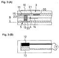
- a gas sensor according to a second embodiment of the present invention shown in FIGS. 3(A) and (B) is characterized in that two cavity portions are provided, and the oxygen sensor cell and the oxygen concentration cell are formed on different layers.
- the gas sensor includes, from top to bottom in FIG. 3(A), an oxygen pump cell 3 that includes a first solid electrolyte layer and paired electrodes 10 and 11 formed on opposite sides of the first solid electrolyte layer, an insulating layer that surrounds a first cavity portion 21 horizontally in FIG.
- an oxygen sensor cell 4 that includes a second solid electrolyte layer and paired oxygen concentration reference electrode 14 and oxygen-concentration-sensing electrode 15 formed on opposite sides of the second solid electrolyte layer, a third electrolyte layer serving as a support cell, an insulating layer that surrounds a second cavity portion 23 horizontally in FIG. 3(A), and an oxygen concentration cell 5 that includes a fourth solid electrolyte and electrodes 12 and 13 formed on the same side of the fourth solid electrolyte layer.
- An insulating layer is interposed between the solid electrolyte layers.
- the first cavity portion 21 is defined between the oxygen pump cell 3 and the oxygen sensor cell 4 by means of the lateral insulating layer shown in FIG.
- First diffusion-controlling passages 20 are formed at laterally opposite end portions of the gas sensor in such a manner as to be exposed to the interior of the first cavity portion 21 at one end, to thereby establish communication between a subject gas atmosphere and the first cavity portion 21 across a diffusion resistance.
- a second diffusion-controlling passage 22 is disposed away from the first diffusion-controlling passages 20 in such a manner as to be exposed to the interior of the first cavity portion 21 at the other end, to thereby establish communication between the first and second cavity portions 21 and 23 across a diffusion resistance.
- the oxygen pump cell 3 pumps out oxygen from and/or pumps oxygen into the first cavity portion 21 on the basis of output from the oxygen sensor cell 4, which is exposed to the interior of the first cavity portion 21, thereby holding constant the concentration of oxygen in gas diffusing into the second cavity portion 23.
- the concentration of gas to be measured is determined by means of the oxygen concentration cell 5, which is exposed to the interior of the second cavity portion 23.
- the oxygen concentration reference electrode 14 serves as a self-generation-type reference electrode as in the case of embodiment 1.
- an active electrode 12 and an inactive electrode 13 are formed on the solid electrolyte layer that constitutes the oxygen concentration cell 5, on the same surface exposed to the interior of the second cavity portion 23.
- the voltage difference between the active electrode 12 and the inactive electrode 13 of the oxygen concentration cell 5 is measured by a voltmeter as shown schematically in FIG. 3(B).
- a pair of electrodes 12, 13 of the oxygen concentration cell 5 may be formed on a single side of the solid electrolyte layer, thereby simplifying the structure of the oxygen concentration cell and reducing man-hours of manufacture as compared to the case where the electrodes are formed on opposite sides of the solid electrolyte layer.
- the active electrode of the oxygen concentration cell and the oxygen-concentration-sensing electrode may be implemented in the form of a common electrode.
- the active and inactive electrodes of the concentration cell which produce an electromotive force for sensing gas are both located in the same cavity and are both exposed to substantially the same atmosphere.
- the sensor is fabricated through lamination of, for example, ZrO 2 green sheets and electrode pastes and firing of the resultant laminate.
- Paste materials for insulating coat and electrodes are screen-printed on predetermined ZrO 2 green sheets (which will become solid electrolyte layers of the oxygen pump cell, oxygen sensor cell, and oxygen concentration cell), thereby forming insulating layers and electrodes at predetermined positions in a laminate. Processes for manufacturing the ZrO 2 green sheet and other elements are described below.
- ZrO 2 powder is preliminarily fired in an atmospheric furnace.
- the preliminarily fired ZrO 2 powder, a dispersant, an organic solvent, and balls are mixed and dispersed.
- an organic binder dissolved in an organic solvent is added, followed by mixing to thereby obtain slurry.
- the thus-obtained slurry is sheeted according to a doctor blading method, yielding a ZrO 2 green sheet having a thickness of approximately 0.4 mm.
- ZrO 2 green sheets each printed with an element by use of a predetermined paste, are laminated and compression-bonded.
- the resulting laminate undergoes binder removal and firing.
- a heater element was bonded to a gas sensor having a structure according to the first embodiment of the present invention shown in FIG. 1. Voltage was applied to the oxygen pump cell such that an electromotive force generated in the oxygen sensor cell assumes a constant value of 350 mV. Gas sensor output (an electromotive force generated between the paired electrodes of the oxygen concentration cell by the concentration cell effect) was measured while NO gas concentration exposed to the gas sensor was varied.
- a Pt electrode ZrO 2 was added in an amount of 14% with respect to an electrode component
- an Aul.5%-Pt electrode ZrO 2 was added in an amount of 14% with respect to an electrode component
- the electrodes were fabricated according to the method described above in the "Embodiments" section.
- the oxygen concentration reference electrode 14 and the outer common electrode 13/14 served as a self-generation-type reference electrode.
- Conditions of measurement in the examples were as follows.
- Gas temperature 300°C.
- Temperature of sensing element of gas sensor 800°C.
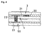
- a gas sensor having a structure shown in FIG. 4 was fabricated as another comparative example according to the method described above in the "Embodiments" section. By use of the gas sensor, measurement was carried out in a manner similar to that described above.
- the gas sensor of comparative example 2 assumes the form of a laminate of four solid electrolyte layers while an insulating layer is interposed between the solid electrolyte layers. Specifically, the first solid electrolyte layer constitutes a first oxygen pump cell 3; the second solid electrolyte layer constitutes an oxygen sensor cell 4; the third solid electrolyte layer constitutes a support cell; and the fourth solid electrolyte layer constitutes a second oxygen pump cell 50.
- a first cavity portion 21 is defined between the first oxygen pump cell 3 and the oxygen sensor cell 4.
- a second cavity portion 23 is defined between the support cell and the second oxygen pump cell 50.
- An exterior atmosphere communicates with the first cavity portion 21 through a first diffusion-controlling passage 20, which is formed of a porous insulator.
- a second diffusion-controlling passage 22, which is formed of a porous insulator, extends between the first cavity portion 21 and the second cavity portion 23 in the direction of lamination to thereby establish communication between the first and second cavity portions 21 and 23.
- the first oxygen pump cell 3 is controlled on the basis of an electromotive force that is generated between a pair of electrodes of the oxygen sensor cell 4 in proportion to oxygen concentration in the first cavity portion 21, so that gas whose oxygen concentration is held at a constant low level diffuses into the second cavity portion 22.
- a constant voltage is applied between a pair of electrodes (Pt electrodes (ZrO 2 is added in an amount of 14% with respect to an electrode component)) of the second oxygen pump cell 50.
- Current that is induced by oxygen ions generated through dissociation of NO and flows between the paired electrodes is measured as gas sensor output.
- FIG. 5 is a graph showing the results of measurement in example 1 and comparative examples 1 and 2.
- FIG. 5 shows the relationship between NO concentration exposed to the gas sensor and an electromotive force, EMF (mV), generated by the concentration cell effect in the case of example 1 and comparative example 1, and the relationship between NO concentration exposed to the gas sensor and oxygen pump current ( ⁇ A) that flows through the second oxygen pump cell in the case of comparative example 2.
- EMF electromotive force
- ⁇ A oxygen pump current
- the electromotive force EMF that the gas sensor generates is on the order of mV
- output from the gas sensor can be detected more easily than in the case of comparative example 2, in which NO gas concentration is determined on the basis of current that is on the order of ⁇ A.
- a gas sensor according to the present invention outputs a high voltage level (of the order of at least mV) across the inactive and active electrodes placed on the same surface of the electrolyte and exposed to substantially the same atmosphere inside the same cavity, because a concentration cell effect is caused along the electrolyte between these electrodes. Therefore a high degree of accuracy in detecting low concentration of a gas component, such as below 100ppm can be attained easily based on such mV order voltage, compared to a conventional current-based measurement.
- the concentration of various gas components can be detected by use of the same mechanical sensor structure simply by changing or rather adjusting the composition of the oxygen concentration cell electrode material of the sensor structure according to the particular component of interest of the gas under measurement which is to be detected. Thus the design and production efficiency of the sensors becomes high because the same basic structure can be used for a variety of different sensors.
- the invention has been described in terms of measuring the concentration of a particular component in a gas based on the voltage measured between the active and inactive electrodes, as shown in the sensitivity characteristic in FIG. 5.
- application of the invention is not limited to this measurement.
- the voltage that appears across the active and inactive electrodes can fluctuate according to the kind of gas mixture entering the cavity as well as according to the amount of the gas component being sensed. For example, suppose the gas contains a constant NOx amount and the proportions of other gas components are also constant. In this state, the measured voltage shows a particular constant value. If an HC gas component joins the gas, then the voltage value instantly changes to a lower level which can be down to zero or even negative.
- the gas sensor could be used to detect that the conditions of the engine emitting the exhaust gas being measured has changed as well as, or instead of, measuring the concentration of a particular gas component in the exhaust gas.
Landscapes
- Chemical & Material Sciences (AREA)
- Life Sciences & Earth Sciences (AREA)
- Health & Medical Sciences (AREA)
- Physics & Mathematics (AREA)
- Chemical Kinetics & Catalysis (AREA)
- Electrochemistry (AREA)
- Molecular Biology (AREA)
- Analytical Chemistry (AREA)
- Biochemistry (AREA)
- General Health & Medical Sciences (AREA)
- General Physics & Mathematics (AREA)
- Immunology (AREA)
- Pathology (AREA)
- Measuring Oxygen Concentration In Cells (AREA)
Applications Claiming Priority (2)
| Application Number | Priority Date | Filing Date | Title |
|---|---|---|---|
| JP26310998A JP3587290B2 (ja) | 1998-09-17 | 1998-09-17 | NOxガスセンサ |
| JP26310998 | 1998-09-17 |
Publications (3)
| Publication Number | Publication Date |
|---|---|
| EP0987548A2 true EP0987548A2 (fr) | 2000-03-22 |
| EP0987548A3 EP0987548A3 (fr) | 2004-09-29 |
| EP0987548B1 EP0987548B1 (fr) | 2010-09-01 |
Family
ID=17384963
Family Applications (1)
| Application Number | Title | Priority Date | Filing Date |
|---|---|---|---|
| EP99307395A Expired - Lifetime EP0987548B1 (fr) | 1998-09-17 | 1999-09-17 | Capteur de gaz |
Country Status (4)
| Country | Link |
|---|---|
| US (1) | US6635162B2 (fr) |
| EP (1) | EP0987548B1 (fr) |
| JP (1) | JP3587290B2 (fr) |
| DE (1) | DE69942714D1 (fr) |
Families Citing this family (19)
| Publication number | Priority date | Publication date | Assignee | Title |
|---|---|---|---|---|
| DE10116184A1 (de) * | 2001-03-31 | 2002-10-10 | Bosch Gmbh Robert | Verfahren und Vorrichtung zur Erfassung der Konzentration einer sauerstoffhaltigen Verbindung in einem Meßgas |
| JP2004037100A (ja) * | 2002-06-28 | 2004-02-05 | Denso Corp | ガスセンサ素子 |
| US20050105664A1 (en) * | 2003-10-30 | 2005-05-19 | Chubb Talbot A. | Process for generating nuclear heat |
| US20050105663A1 (en) * | 2003-10-30 | 2005-05-19 | Chubb Talbot A. | Apparatus for generating nuclear heat |
| US20080205572A1 (en) * | 2003-10-30 | 2008-08-28 | Chubb Talbot A | Apparatus and process for generating nuclear heat |
| US7114325B2 (en) * | 2004-07-23 | 2006-10-03 | Ford Global Technologies, Llc | Control system with a sensor |
| US7611612B2 (en) | 2005-07-14 | 2009-11-03 | Ceramatec, Inc. | Multilayer ceramic NOx gas sensor device |
| US7864322B2 (en) * | 2006-03-23 | 2011-01-04 | The Research Foundation Of State University Of New York | Optical methods and systems for detecting a constituent in a gas containing oxygen in harsh environments |
| DE102006060633A1 (de) * | 2006-12-21 | 2008-06-26 | Robert Bosch Gmbh | Verfahren zum Betreiben eines Sensorelements und Sensorelement zur Bestimmung der Konzentration von Gaskomponenten in einem Gasgemisch |
| JP4270286B2 (ja) * | 2007-02-07 | 2009-05-27 | トヨタ自動車株式会社 | ガスセンサ用の制御装置 |
| JP4578556B2 (ja) * | 2008-05-12 | 2010-11-10 | 日本特殊陶業株式会社 | ガスセンサ及びその製造方法 |
| JP5749782B2 (ja) * | 2010-03-29 | 2015-07-15 | 日本碍子株式会社 | ガスセンサ |
| JP2011227061A (ja) | 2010-03-29 | 2011-11-10 | Ngk Insulators Ltd | ガスセンサ |
| US9164080B2 (en) | 2012-06-11 | 2015-10-20 | Ohio State Innovation Foundation | System and method for sensing NO |
| JP7237866B2 (ja) * | 2019-04-08 | 2023-03-13 | 日本特殊陶業株式会社 | NOxセンサ素子及びNOxセンサ |
| CN113203784B (zh) * | 2021-05-20 | 2022-10-18 | 安徽中科国瓷新型元器件有限公司 | 变频氧传感器 |
| JP7725405B2 (ja) * | 2022-03-24 | 2025-08-19 | 日本碍子株式会社 | ガスセンサ |
| WO2023243582A1 (fr) * | 2022-06-17 | 2023-12-21 | 日本碍子株式会社 | Élément sensible et capteur de gaz |
| CN115684297B (zh) * | 2022-10-08 | 2025-01-24 | 浙江百岸科技有限公司 | 一种泵单元独立设计的氮氧传感器芯片 |
Family Cites Families (12)
| Publication number | Priority date | Publication date | Assignee | Title |
|---|---|---|---|---|
| SE513477C2 (sv) * | 1993-11-08 | 2000-09-18 | Volvo Ab | Sensor för detektering av kväveoxidföreningar |
| US5672811A (en) * | 1994-04-21 | 1997-09-30 | Ngk Insulators, Ltd. | Method of measuring a gas component and sensing device for measuring the gas component |
| JP3524980B2 (ja) * | 1995-03-10 | 2004-05-10 | 株式会社リケン | 窒素酸化物センサ |
| US5948964A (en) | 1995-10-20 | 1999-09-07 | Ngk Insulators, Ltd. | NOx sensor and method of measuring NOx |
| JP3272215B2 (ja) * | 1995-10-20 | 2002-04-08 | 日本碍子株式会社 | NOxセンサ及びNOx測定方法 |
| JP3647181B2 (ja) * | 1996-02-23 | 2005-05-11 | 日本碍子株式会社 | 窒素酸化物の測定方法 |
| JP3128114B2 (ja) * | 1996-04-08 | 2001-01-29 | 株式会社リケン | 窒素酸化物検出装置 |
| JP3537628B2 (ja) * | 1996-05-16 | 2004-06-14 | 日本碍子株式会社 | 窒素酸化物の測定方法 |
| US6071393A (en) * | 1996-05-31 | 2000-06-06 | Ngk Spark Plug Co., Ltd. | Nitrogen oxide concentration sensor |
| JP3293741B2 (ja) * | 1996-06-06 | 2002-06-17 | 株式会社リケン | NOxセンサ |
| US6303011B1 (en) * | 1997-06-23 | 2001-10-16 | Kabushiki Kaisha Riken | Gas sensor |
| JP3372195B2 (ja) * | 1997-08-14 | 2003-01-27 | 日本特殊陶業株式会社 | NOxガス濃度検出器及び検出器に用いる電極の製造方法 |
-
1998
- 1998-09-17 JP JP26310998A patent/JP3587290B2/ja not_active Expired - Fee Related
-
1999
- 1999-09-17 US US09/397,931 patent/US6635162B2/en not_active Expired - Lifetime
- 1999-09-17 EP EP99307395A patent/EP0987548B1/fr not_active Expired - Lifetime
- 1999-09-17 DE DE69942714T patent/DE69942714D1/de not_active Expired - Lifetime
Non-Patent Citations (1)
| Title |
|---|
| SAE PAPER NO. 960334, 1996, pages 137 - 142 |
Also Published As
| Publication number | Publication date |
|---|---|
| EP0987548A3 (fr) | 2004-09-29 |
| JP3587290B2 (ja) | 2004-11-10 |
| JP2000088796A (ja) | 2000-03-31 |
| US20030070924A1 (en) | 2003-04-17 |
| EP0987548B1 (fr) | 2010-09-01 |
| DE69942714D1 (de) | 2010-10-14 |
| US6635162B2 (en) | 2003-10-21 |
Similar Documents
| Publication | Publication Date | Title |
|---|---|---|
| US6635162B2 (en) | Gas sensor | |
| US6773565B2 (en) | NOx sensor | |
| EP0257842B1 (fr) | Détecteur électrochimique de NOx | |
| US6787014B2 (en) | Gas-detecting element and gas-detecting device comprising same | |
| US6579435B2 (en) | Gas sensor | |
| EP1074834B1 (fr) | Procédé et appareil de mesure de la concentration d'oxydes d'azote | |
| US6579436B2 (en) | Gas sensor and method of producing the same | |
| US4882033A (en) | Electrochemical device | |
| KR100319010B1 (ko) | 가스센서 | |
| EP0903575B1 (fr) | Capteur pour oxyde de nitrogène | |
| US20020108854A1 (en) | Gas sensor | |
| JP4763203B2 (ja) | ガス混合物中のガス成分の濃度の測定のためのガスセンサ及びその使用 | |
| US6338782B1 (en) | Gas sensor | |
| KR100230510B1 (ko) | 가스 혼합물의 가스 성분 및 가스 농도를 결정하기 위한 감지장치 | |
| US7241477B2 (en) | Methods of treating electrodes and gas sensors comprising the electrodes | |
| US6746584B1 (en) | Oxygen sensing device | |
| JP2003518619A (ja) | ガス成分を測定するためのガスセンサーのセンサー素子 | |
| EP1006354A2 (fr) | Capteur de gaz et dispositif pour mesurer la concentration d'un composant combustible d'un gaz | |
| JP4625261B2 (ja) | ガスセンサのセンサ素子 | |
| US6797138B1 (en) | Gas senior design and method for forming the same | |
| US20030075441A1 (en) | Sensor element of a gas sensor | |
| JP3943262B2 (ja) | NOxガス濃度測定装置及びNOxガス濃度測定方法 | |
| EP0178149A1 (fr) | Procédé de détection de la pression partielle d'oxygène | |
| EP0987547A2 (fr) | Capteur de gaz | |
| JPH1183795A (ja) | ガスセンサ及び可燃性ガス成分濃度の測定方法 |
Legal Events
| Date | Code | Title | Description |
|---|---|---|---|
| PUAI | Public reference made under article 153(3) epc to a published international application that has entered the european phase |
Free format text: ORIGINAL CODE: 0009012 |
|
| AK | Designated contracting states |
Kind code of ref document: A2 Designated state(s): AT BE CH CY DE DK ES FI FR GB GR IE IT LI LU MC NL PT SE |
|
| AX | Request for extension of the european patent |
Free format text: AL;LT;LV;MK;RO;SI |
|
| PUAL | Search report despatched |
Free format text: ORIGINAL CODE: 0009013 |
|
| AK | Designated contracting states |
Kind code of ref document: A3 Designated state(s): AT BE CH CY DE DK ES FI FR GB GR IE IT LI LU MC NL PT SE |
|
| AX | Request for extension of the european patent |
Extension state: AL LT LV MK RO SI |
|
| RIC1 | Information provided on ipc code assigned before grant |
Ipc: 7G 01N 27/419 B Ipc: 7G 01N 27/407 B Ipc: 7G 01N 27/417 A |
|
| 17P | Request for examination filed |
Effective date: 20050329 |
|
| AKX | Designation fees paid |
Designated state(s): DE FR |
|
| 17Q | First examination report despatched |
Effective date: 20070813 |
|
| GRAP | Despatch of communication of intention to grant a patent |
Free format text: ORIGINAL CODE: EPIDOSNIGR1 |
|
| GRAS | Grant fee paid |
Free format text: ORIGINAL CODE: EPIDOSNIGR3 |
|
| GRAA | (expected) grant |
Free format text: ORIGINAL CODE: 0009210 |
|
| AK | Designated contracting states |
Kind code of ref document: B1 Designated state(s): DE FR |
|
| REF | Corresponds to: |
Ref document number: 69942714 Country of ref document: DE Date of ref document: 20101014 Kind code of ref document: P |
|
| PLBE | No opposition filed within time limit |
Free format text: ORIGINAL CODE: 0009261 |
|
| STAA | Information on the status of an ep patent application or granted ep patent |
Free format text: STATUS: NO OPPOSITION FILED WITHIN TIME LIMIT |
|
| 26N | No opposition filed |
Effective date: 20110606 |
|
| REG | Reference to a national code |
Ref country code: DE Ref legal event code: R097 Ref document number: 69942714 Country of ref document: DE Effective date: 20110606 |
|
| PGFP | Annual fee paid to national office [announced via postgrant information from national office to epo] |
Ref country code: FR Payment date: 20140906 Year of fee payment: 16 |
|
| REG | Reference to a national code |
Ref country code: FR Ref legal event code: ST Effective date: 20160531 |
|
| PG25 | Lapsed in a contracting state [announced via postgrant information from national office to epo] |
Ref country code: FR Free format text: LAPSE BECAUSE OF NON-PAYMENT OF DUE FEES Effective date: 20150930 |
|
| PGFP | Annual fee paid to national office [announced via postgrant information from national office to epo] |
Ref country code: DE Payment date: 20160913 Year of fee payment: 18 |
|
| REG | Reference to a national code |
Ref country code: DE Ref legal event code: R119 Ref document number: 69942714 Country of ref document: DE |
|
| PG25 | Lapsed in a contracting state [announced via postgrant information from national office to epo] |
Ref country code: DE Free format text: LAPSE BECAUSE OF NON-PAYMENT OF DUE FEES Effective date: 20180404 |