EP0987619A2 - Appareil d'expansion de fonction et équipement électronique - Google Patents
Appareil d'expansion de fonction et équipement électronique Download PDFInfo
- Publication number
- EP0987619A2 EP0987619A2 EP99306747A EP99306747A EP0987619A2 EP 0987619 A2 EP0987619 A2 EP 0987619A2 EP 99306747 A EP99306747 A EP 99306747A EP 99306747 A EP99306747 A EP 99306747A EP 0987619 A2 EP0987619 A2 EP 0987619A2
- Authority
- EP
- European Patent Office
- Prior art keywords
- electronic equipment
- notebook
- undocking
- function
- docking station
- Prior art date
- Legal status (The legal status is an assumption and is not a legal conclusion. Google has not performed a legal analysis and makes no representation as to the accuracy of the status listed.)
- Ceased
Links
Images


Classifications
-
- G—PHYSICS
- G06—COMPUTING OR CALCULATING; COUNTING
- G06F—ELECTRIC DIGITAL DATA PROCESSING
- G06F1/00—Details not covered by groups G06F3/00 - G06F13/00 and G06F21/00
- G06F1/16—Constructional details or arrangements
- G06F1/1613—Constructional details or arrangements for portable computers
- G06F1/1632—External expansion units, e.g. docking stations
Definitions
- the present invention generally relates to a function-expansion device and electronic equipment, and more particularly to a function-expansion device and electronic equipment, the function-expansion device being detachably connected to the electronic equipment to provide extended functions of the electronic equipment.
- the notebook PC 10 has a connector 11 on the bottom of the notebook PC 10, and the expansion station 20 has a connector 21 on the top of the expansion station 20 at a position corresponding to a position of the connector 11 on the notebook PC 10.
- the connector 11 and the connector 21 are connected to each other.
- a floppy disk drive 22 and a CD-ROM drive 23 are provided in the expansion station 20 .
- the floppy disk drive 22 acts to read information from or write information to a floppy disk 30.
- the CD-ROM drive 23 acts to read information from a CD-ROM 40.
- the functions of the floppy disk drive 22 and the CD-ROM drive 23, which require a relatively large amount of power consumption, are not provided on the notebook PC 10, and these functions are provided only when the expansion station 20 is attached to the notebook PC 10.
- the floppy disk drive 22 and the CD-ROM drive 23 are integrally provided on the expansion station 20 in a fixed manner.
- information recording media that can be used with the notebook PC 10 are limited to the floppy disk and the CD-ROM.
- Other recording media such as magnetooptical disks (MO), digital video disks (DVD) or high-capacity floppy disks (LS-120), cannot be used with the notebook PC 10.
- the range of expansion of the functions provided by the expansion station 20 is restricted, and the conventional electronic equipment system 1 does not provide an adequate level of operability, or ease of use, for the user.
- the conventional electronic equipment system 1 when the user intends to detach the expansion station 20 from the notebook PC 10, it is required to stop operation of the notebook PC 10 or turn off a power switch of the notebook PC 10.
- the conventional electronic equipment system 1 does not provide an adequate level of operability, or ease of use, for the user, even through the expansion station 20 provides extended functions of the notebook PC 10.
- the conventional electronic equipment system 1 including the expansion station 20 is intended for the desktop use, and it is not intended to provide portability. As shown in FIG. 1, the expansion station 20 has a size that is equivalent to a size of the notebook PC 10. It is difficult for the user to carry the notebook PC 10 with the expansion station 20 attached thereto. The conventional electronic equipment system 1 including the expansion station 20 is not easily portable, which may cause inconvenience to the user.
- An object of the present invention is to provide an improved function-expansion device in which the above-mentioned problems are eliminated.
- Another object of the present invention is to provide a function-expansion device which provides an adequate level of operability for the user and includes a component unit detachable from the function-expansion device when the function-expansion device is connected to electronic equipment which is in an operating condition.
- Still another object of the present invention is to provide an electronic equipment system including a function-expansion device which provides an adequate level of operability for the user and includes a component unit detachable from the function-expansion device when the function-expansion device is connected to electronic equipment which is in an operating condition.
- a function-expansion device detachably connected to electronic equipment to expand functions of the electronic equipment
- the function-expansion device including: a component unit which provides an extended function of the electronic equipment; and a docking station which detachably mounts the component unit on the docking station, the docking station connecting the component unit to the electronic equipment, wherein the component unit is detachable from the docking station when the docking station is attached to the electronic equipment which is in an operating condition.
- an electronic equipment system including a function-expansion device and electronic equipment, the function-expansion device detachably connected to the electronic equipment to expand functions of the electronic equipment, the function-expansion device including: a component unit which provides an extended function of the electronic equipment; and a docking station which detachably mounts the component unit on the docking station, the docking station connecting the component unit to the electronic equipment, wherein the component unit is detachable from the docking station when the docking station is attached to the electronic equipment which is in an operating condition.
- the component unit is detachable from the docking station when the function-expansion device is connected to the electronic equipment which is in an operating condition.
- the component unit in the function-expansion device is exchanged for a new component unit, it is not necessary to stop operation of the electronic equipment or turn off a power switch of the electronic equipment. It is possible to exchange the component unit for the new component unit even when the electronic equipment is operating.
- the function-expansion device of the present invention is effective in providing an adequate level of operability for the user.
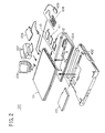
- FIG. 2 shows a configuration of an electronic equipment system embodying the present invention.
- a color CRT (cathode-ray tube) display 106, a printer 107, a ten-key board 108 and a mouse 109 can be externally connected to the notebook PC 101.
- a variety of PC cards which are in conformity with PCMCIA (Personal Computer Memory Card International Association) standard can be externally connected to the notebook PC 101.
- the above-mentioned PC cards include an SCSI (small computer system interface) card 110, an IC (integrated circuit) memory card 111 and an LAN (local area network) card 112.
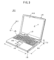
- FIG. 3 shows the notebook PC 101 in the electronic equipment system 100.
- FIG. 4A shows a left side of the notebook PC 101
- FIG. 4B shows a right side of the notebook PC 101.
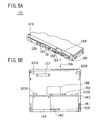
- FIG. 5A shows a back of the notebook PC 101
- FIG. 5B shows a bottom of the notebook PC 101.
- the display part 114 is rotated on the host PC 113 in the direction D2. Internal surfaces of the host PC 113 and the display part 114 are uncovered as shown in FIG. 4A, and the notebook PC 101 can operate in this condition.
- a keyboard 115 and a pointing device 116 on the top of the host PC 113 are uncovered.
- the user can input a command and data to the notebook PC 101 by using the keyboard 115, and can move a pointer "P" on the monitor of the display part 114 by using the pointing device 116.
- An operating state indicator 117 is provided at a rear position on the top of the host PC 113. The operating state indicator 117 provides an indication of an operating state of the notebook PC 101.
- a power switch 118 is provided on the left side of the host PC 113.
- the power switch 118 is turned on or off, the operation of the notebook PC 101 is started or terminated.
- a volume control 119, a headphone jack 120, a microphone jack 121, a LINE-IN jack 122, an anti-theft lock 123, a modular connector 124, a PC card lock 125, a PC card slot 126 and a PC card eject button 127 are provided on the right side of the host PC 113.
- an infrared communication port 128, a USB (universal serial bus) connector 129, an expansion keyboard/mouse connector 130, a floppy disk drive connector 131, a serial interface connector 132, a parallel interface connector 133, a CRT interface connector 134, a DC-IN connector 135 and an expansion connector cover 136 are provided on the back of the host PC 113.
- the infrared communication port 128 provides an interface needed to perform an infrared communication.
- a peripheral device (not shown) which is in conformity with USB (universal serial bus) standard is connected to the USB connector 129.
- the ten-key board 108 or the mouse 109 is connected to the expansion keyboard/mouse connector 130.
- the floppy disk drive unit 105 is connected to the floppy disk drive connector 131.
- An external device (not shown) having an interface in conformity with RS-232C standard is connected to the serial interface connector 132.
- the printer 107 or the like is connected to the parallel interface connector 133.
- the color CRT display 106 is connected to the CRT interface connector 134.
- An AC adapter (not shown) which externally supplies source power to the notebook PC 101 is connected to the DC-IN connector 135.
- the expansion connector cover 136 provides protection for the connectors on the back of the host PC 113 when the notebook PC 101 is carried by the user.
- the expansion station 102 and the compact bay case 104 are connected to the expansion unit connector 137.
- An expansion RAM module (not shown) is inserted into the expansion RAM slot 138.
- the battery pack lock 139 acts to lock the battery pack 103 in the battery pack slot 141 when the battery pack 103 is inserted into the battery pack slot 141.
- the unlock button 140 acts to unlock the battery pack 103.
- the battery pack 103 is inserted into the battery pack slot 141.
- a built-in hard disk drive unit 143 is inserted into the hard disk drive slot 142.
- a liquid crystal display 144 is provided on the internal surface of the display part 114, and an image is displayed on the liquid crystal display 144.
- the notebook PC 101 includes a CPU, a RAM, a ROM, an interface circuit and a communication circuit which are incorporated in the host PC 113, and these elements enable the notebook PC 101 to carry out information processing.
- FIG. 6 shows the expansion station 102 in the electronic equipment system 100 of the present embodiment.
- FIG. 7 shows a back of the expansion station 102 in the electronic equipment system 100.
- a built-in battery pack slot 145, a built-in battery pack lock 146, a connector 147, connector locks 148, a CD-ROM drive 149, a CD-ROM eject button 150, a release button 151, a release enable lamp 152, a floppy disk drive 153, a floppy disk eject button 154, a PC card slot 155 and a release lever 156 are provided on the expansion station 102.
- the battery pack 103 is inserted into the battery pack slot 145.
- the battery pack slot 145 is provided for mounting the battery pack 103 on the expansion station 102, and the battery pack 103 supplies power to the expansion station 102 and the notebook PC 101.
- the battery pack lock 146 acts to lock the battery pack 103 in the battery pack slot 145.
- the connector 147 is connected to the expansion unit connector 137 on the bottom of the host PC 113, so that the expansion station 102 and the host PC 113 are connected to each other.
- the connector locks 148 are fitted to recessed portions 209 (FIG. 5B) of the bottom of the host PC 113, so that the expansion station 102 is mechanically connected to the host PC 113.
- a CD-ROM 157 is inserted into the CD-ROM drive 149, and the CD-ROM drive 149 acts to read information from the CD-ROM 157.
- the CD-ROM eject button 150 acts to eject the CD-ROM 157 from the CD-ROM drive 149.
- the release button 151 acts to release the expansion station 102 from the notebook PC 101.
- the release enable lamp 152 is comprised of an LED (light emitting diode). The release enable lamp 152 is turned on when the notebook PC 101 is set in a condition that the expansion station 102 can be removed from the notebook PC 101.
- a floppy disk 158 is inserted into the floppy disk drive 153, and the floppy disk drive 153 acts to read information from or write information to the floppy disk 158.
- the floppy disk eject button 154 acts to eject the floppy disk 158 from the floppy disk drive 153.
- a PC card 159 is inserted into the PC card slot 155.
- the release lever 156 is pulled by the user before the expansion station 102 is released from the notebook PC 101.
- the release lever 156 acts to release the mechanical connection between the notebook PC 101 and the expansion station 102.
- the connector 216 When the floppy disk drive unit 215 is mounted in the expansion bay 201 of the compact bay case 104, the connector 216 is connected to the connector 216A, so that the floppy disk drive unit 215 and the notebook PC 101 are interconnected by the connection of the connector 216 and the connector 216A. Further, when the floppy disk drive unit 215 is mounted in the expansion bay 201, the floppy disk insertion opening 217 is located at the insertion opening 205 of the compact bay case 104. A floppy disk (not shown) can be easily inserted into or withdrawn from the floppy disk drive unit 215 through the floppy disk insertion opening 216.
- FIG. 13A and FIG. 13B show the battery pack 103 in the electronic equipment system 100.
- the battery pack 103 is viewed from a lower position.
- the battery pack 103 which is turned upside down is viewed from an upper position.
- the battery pack slot 141 includes a recess 180, a contact terminal 181, connecting portions 182 and the battery pack lock 139.
- the recess 180 is formed on either the top or the bottom of one of the notebook PC 101, the expansion station 102 and the compact bay case 104.
- the recess 180 has a configuration that is the same as the configuration of the battery pack 103.
- the contact terminal 181 is electrically connected to the terminal 174 of the battery pack 103 when the battery pack 103 is inserted into the recess 180.
- the connecting portions 182 are fitted to the recessed portions 175-179 of the battery pack 103 when the battery pack 103 is inserted into the recess 180.
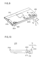
- FIG. 15 is a diagram for explaining insertion of the battery pack 103 into and withdrawal of the battery pack 103 from the battery pack slot 141.
- the notch portion 173 of the battery pack 103 is matched with a corresponding portion of the recess 180 of the battery pack slot 141. While the notch portion 173 is matched with the corresponding portion of the recess 180, the battery pack 103 is rotated in a direction indicated by the arrow 184. Then, the battery pack 103 is completely inserted into the recess 180 of the battery pack slot 141.
- FIG. 16 is a diagram for explaining attaching of the compact bay case 104 to and detaching of the compact bay case 104 from the notebook PC 101.
- the compact bay case 104 is attached to the bottom of the notebook PC 101 when used.
- the floppy disk drive unit 215 or the CD-ROM drive unit 218 is mounted in the expansion bay 201 of the compact bay case 104 as an optional component unit 221 which provides an extended function of the notebook PC 101.
- the electronic equipment system 100 of the present embodiment is characterized in that the optional component unit 221 (the floppy disk drive unit 215 or the CD-ROM drive unit 218) is detachable from the compact bay case 104 when the compact bay case 104 is attached to the notebook PC 101 which is in an operating condition.
- the optional component unit 221 the floppy disk drive unit 215 or the CD-ROM drive unit 2128 is detachable from the compact bay case 104 when the compact bay case 104 is attached to the notebook PC 101 which is in an operating condition.
- the compact bay case 104 When the compact bay case 104 containing the optional component unit 221 which is mounted in the expansion bay 201 is attached to the notebook PC 101, or when the optional component unit 221 is inserted into the vacant expansion bay 201 of the compact bay case 104 which is attached to the notebook PC 101, the compact bay case 104 transmits a connection request to the notebook PC 101 so that the notebook PC 101 recognizes the presence of the optional component unit 221 in the electronic equipment system 100.
- the compact bay case 104 containing the optional component unit 221 which is mounted in the expansion bay 201 is detached from the notebook PC 101, or when the optional component unit 221 is detached from the compact bay case 104 which is attached to the notebook PC 101, the user presses the undocking request button 213 on the side of the compact bay case 104.
- the undocking request button 213 is pressed, the compact bay case 104 transmits an undocking request to the notebook PC 101, and the undocking request causes the notebook PC 101 to permit the detachment of the optional component unit 221 from the compact bay case 104.
- the compact bay case 104 receives an undocking acknowledge signal output by the notebook PC 101, and the undocking acknowledge signal indicates that the notebook PC 101 has permitted the detachment.
- the undocking indicator LED 214 is turned on to provide an indication that the detachment of the optional component unit 221 from the compact bay case 104 is permitted.
- the optional component unit 221 can be detached from the compact bay case 104 when the compact bay case 104 is attached to the notebook PC 101 which is in an operating condition.
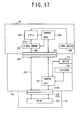
- FIG. 17 is a block diagram of an essential part of the electronic equipment system 100 which deals with the attaching of the compact bay case 104 to and the detaching of the compact bay case 104 from the notebook PC 101.
- the connector 137 of the notebook PC 101 and the connector 203 of the compact bay case 104 are connected to each other, and the connector 216A of the compact bay case 104 and the connector 216 (or 219) of the optional component unit 221 are connected to each other.
- the connector 137 is connected through a PCI (peripheral component interconnect) bus 222 to a signal buffer 223, and the signal buffer 223 is connected through a PCI bus 222a to a CPU 224.
- a control unit 225 is connected to each of the CPU 224, the signal buffer 223 and the connector 137, and various control signals are transmitted between the control unit 225 and these elements 224, 223 and 137. Further, an input device 229 is connected to the CPU 224.
- the control unit 225 executes a control process when attaching the compact bay case 104 (or the expansion station 102) to the notebook PC 101 or when detaching the compact bay case 104 (or the expansion station 102) from the notebook PC 101.
- the connector 203 is connected through a PCI bus 226 to the connector 216A.
- the connector 203 is also connected to a control unit 227, and the control unit 227 is connected to the connector 216A.
- the undocking request button (SWITCH) 213 is connected to the control unit 227, and the undocking indicator LED (INDICATOR) 214 is connected to the control unit 227.
- FIG. 18 shows a control process executed by the control unit 227 of the compact bay case 104 when the compact bay case 104 is attached to the notebook PC 101 during operation.
- the control unit 227 is power-on reset by the power supplied from the notebook PC 101.
- the control unit 227 at step S1-1 detects whether it is power-on reset. When the result at the step S1-1 is negative, the detection at step S1-1 is repeated. When the result at step S1-1 is affirmative, the control unit 227 at step S1-2 transmits a connection request to the control unit 225 of the notebook PC 101 via the connectors 203 and 137. After the connection request is output to the notebook PC 101, the control process of FIG. 18 is terminated.
- the control unit 225 at step S2-1 detects whether a connection request from the control unit 227 is received at the notebook PC 101. When the result at the step S2-1 is negative, the detection at step S2-1 is repeated. When the result at step S2-1 is affirmative, the control unit 225 at step S2-2 performs a bus connection by controlling the signal buffer 223 so as to connect the PCI bus 222a and the PCI bus 226 of the compact bay case 104. After the bus connection is performed at step S2-2, the control unit 225 at step S2-3 causes the CPU 224 to recognize the presence of the drive 228 of the optional component unit 221.
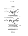
- FIG. 20 shows a control process executed by the control unit 227 of the compact bay case 104 when the compact bay case 104 is detached from the notebook PC 101 during operation.
- the control unit 227 at step S3-1 detects whether the undocking request button 213 is pressed by the user. When the result at step S3-1 is affirmative, the control unit 227 at step S3-2 transmits an undocking request signal to the control unit 225 of the notebook PC 101. Otherwise the detection at step S3-1 is repeated.
- the control unit 227 at step S3-3 detects whether an undocking acknowledge signal output by the control unit 225 is received at the compact bay case 104. When the result at step S3-3 is affirmative, the control unit 227 at step S3-4 turns on the undocking indicator 214. Otherwise the detection at step S3-3 is repeated. If the undocking indicator 214 is turned on, an indication that the detachment of the optional component unit 221 from the compact bay case 104 is permitted by the notebook PC 101 is provided for the user.
- the control unit 225 at step S4-1 detects whether an undocking request signal output by the control unit 227 is received. When the result at step S4-1 is affirmative, the control unit 225 at step S4-2 causes the CPU 224 to perform an undocking process. Otherwise the detection at step S4-1 is repeated. During the undocking process by the CPU 224, the recognition of the drive 228 of the optional component unit 221 is canceled.
- the control unit 225 at step S4-3 detects whether the undocking process by the CPU 224 is complete. When the result at step S4-3 is affirmative, the control unit 225 at step S4-4 transmits an undocking acknowledge signal to the control unit 227 of the compact bay case 104. Otherwise the detection at step S4-3 is repeated.
- the undocking acknowledge signal, transmitted to the control unit 227, indicates that the notebook PC 101 has permitted the detachment of the compact bay case 104 from the notebook PC 101 or the detachment of the optional component unit 221 from the compact bay case 104.
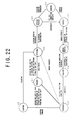
- FIG. 22 shows a transition of docking conditions of the electronic equipment system 100.
- the electronic equipment system 100 of the present embodiment during operation is controlled to have a transition of docking conditions shown in FIG. 22.
- the docking conditions of FIG. 22 include a removed state S1, an attached state S2, a docking process state S3, a docked state S4, an undocking process state S5, an isolated state S6, an undocked state S7, and a suspended state S8.
- the electronic equipment system 100 during operation is controlled to be in one of these states S1-S8.
- the expansion station 102 is detached from the notebook PC 101
- the compact bay case 104 is detached from the notebook PC 101
- the optional component unit 221 is detached from the compact bay case 104 while the compact bay case 104 is attached to the notebook PC 101.
- the docked state S4 is a state of the electronic equipment system 100 in which the docking of the expansion station 102 and the notebook PC 101 is complete, or the docking of the optional component unit 221 and the compact bay case 104 attached to the notebook PC 101 is complete.
- the completion of the docking means that both the PCI bus connection and the docking notification to the software of the notebook PC 101 are carried out.
- the electronic equipment system 100 changes to the docked state S4, the configuration of the resources of the electronic equipment system 100 is restarted. As a result of the configuration, the devices newly docked to the electronic equipment system 100 are recognized by the CPU 224 of the notebook PC 101 so that the devices are available.
- the electronic equipment system 100 changes from the docked state S4 to the undocking process state S5 at a start of an undocking process when the undocking request button on the compact bay case 104 or the expansion station 102 is pressed by the user or when an undocking request icon on the display monitor of the notebook PC 101 is clicked by the user.
- the undocking process is started by an event UNDKREQ# issued by the software of the notebook PC 101.
- interrupt requests are sent to device drivers recognized by the operating system kernel, and the PCI bus isolation request for the undocking is issued by the BIOS (basic input output system) and the device drivers after the interrupt requests are accepted.
- BIOS basic input output system
- the electronic equipment system 100 When the electronic equipment system 100 is in the isolated state S6, the PCI bus isolation between the notebook PC 101 and the expansion station 102 is being performed, or the PCI bus isolation between the notebook PC 101 and the compact bay case 104 is being performed. After the PCI bus isolation is complete, an event UNDKSMI# is issued to notify the software of the notebook PC 101 that the undocking is performed. After the notification of the undocking is performed, the electronic equipment system 100 changes from the isolated state S6 to the undocked state S7.
- the electronic equipment system 100 changes from the docked state S4 to the suspended state S8, the PCI bus between the notebook PC 101 and the expansion station 102 or the PCI bus between the optional component unit 221 and the compact bay case 104 is automatically isolated.
- the electronic equipment system 100 In order to allow the electronic equipment system 100 to change from the suspended state S8 to the docked state S4, it is necessary to perform the PCI bus connection between the notebook PC 101 and the expansion station 102 or the PCI bus connection between the optional component unit 221 and the compact bay case 104.
- the electronic equipment system 100 must change from the suspended state S8 to the docked state S4 through the docking process state S3.
- the electronic equipment system 100 When the electronic equipment system 100 is in the undocked state S7 and a suspend command is issued, the electronic equipment system 100 changes to the suspended state S8. Further, when the electronic equipment system 100 is in the suspended state S8 and a resuming operation is performed, the electronic equipment system 100 changes to the attached state S2. At this time, an event DKSITSMI# is issued to notify the software of the notebook PC 101 that the docking is performed.
- the electronic equipment system 100 of the present embodiment during operation changes from one of the docking conditions to another due to occurrence of any of the events (or the interrupt requests) DKSITSMI#, UNDKREQ#, DOCKSMI# and UNDKSMI#.
- the event DOCKSMI# is issued to notify the software of the notebook PC 101 that the PCI bus between the expansion station 102 and the notebook PC 101 or the PCI bus between the optional component unit 221 of the compact bay case 104 and the notebook PC 101 is connected to each other.
- the transition of the docking conditions of the electronic equipment system 100 as described above is caused by the event DOCKSMI#.
- the interrupt request signals of the events DKSITSMI#, UNDKREQ#, DOCKSMI# and UNDKSMI# when each of the events is issued are respectively transmitted to a connection controller 302 (which will be described later) of the notebook PC 101.
- the control unit 225 of the notebook PC 101 generally has a connection controller 302, a docking sequencer 303, and a notification circuit 304.
- the control unit 225 of the notebook PC 101 in FIG. 17 is referred to as the connection circuit 301 in FIG. 23.
- the CPU 224 of the notebook PC 101 in FIG. 17 is referred to as the CPU 305 in FIG. 23.
- the docking sequencer 303 is initiated in accordance with an instruction output by the CPU 305, and outputs the interrupt request signal of one of the events DOCKSMI# and UNDKSMI# to the connection controller 302. Hence, the transition of the docking conditions of the electronic equipment system 100 as described above is caused by the docking notification event DOCKSMI# or the undocking notification event UNDKSMI#.
- the notification circuit 304 supplies an interrupt signal to the software of the notebook PC 101 which is processed by the CPU 305.
- the software issues a query command to the connection controller 302, and receives a return value of the query command from the connection controller 302.
- the cause of the interrupt supplied by the notification circuit 304 can be recognized by the software of the notebook PC 101.
- the notification circuit 304 supplies a status clear signal CLRFLG# to the expansion station 102 or the control unit 227 of the compact bay case 104.
- the status clear signal is supplied to clear the event status of the expansion station 102 or the compact bay case 104.
- the control unit 227 of the compact bay case 104 cancels the latch of the events DKSITSMI# and UNDKREQ#, and is allowed to accept a subsequent interrupt.
- the expansion station 102 When the expansion station 102 is attached to the notebook PC 101, internal signals CD1# and CD2# which confirm the connection of the expansion station 102 and the notebook PC 101 are asserted, and the interrupt request signal DKSITSMI#, output to the connection controller 302, is set in the low state after the internal signals CD1# and CD2# become stable.
- the output of the interrupt request signal DKSITSMI# is performed when the notebook PC 101 is in the off state, the sleep state or the on state.
- the connection controller 302 is able to accept the low-state interrupt request signal DKSITSMI# output by the expansion station 102.
- the notification circuit 304 of the notebook PC 101 supplies a status clear signal CLRFLG# to the control unit 227 of the compact bay case 104.
- the status clear signal is supplied to clear the event status of the compact bay case 104.
- the control unit 227 of the compact bay case 104 cancels the latch of the event DKSITSMI#, and is allowed to accept a subsequent interrupt.
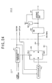
- the docking request generating unit 400 in the present embodiment is constituted by both a first control circuit 401 which is provided in the control unit 227 of the compact bay case 104 and a second control circuit 402 which is provided in the control unit 225 of the notebook PC 101.
- the first control circuit 401 includes, as shown in FIG. 24, a first logic circuit 411, a second logic circuit 412, a flip-flop 413 and a diode 414.
- a signal LEDON# which is set in the low state when the undocking indicator LED is turned on, and a power-supply signal POWERGOOD which is set in the high state when the source power is properly supplied to the compact bay case 104 are supplied from internal circuits of the compact bay case 104 to the first logic circuit 411.
- a signal SUSTAT# is supplied from the notebook PC 101 to the first logic circuit 411.
- the undocking request generating unit 500 in the present embodiment is constituted by both a first control circuit 501 which is provided in the control unit 227 of the compact bay case 104 and a second control circuit 502 which is provided in the control unit 225 of the notebook PC 101.
- the undocking request (or the interrupt request signal UNDKREQ#) is output from an inversion output Q# of the flip-flop 516 to the second control circuit 502 of the notebook PC 101.
- the interrupt request signal UNDKREQ# is supplied through the diode 517 to the second control circuit 502 of the notebook PC 101.
- the diode 517 acts to perform the blocking of the interrupt request signal UNDKREQ# from -the notebook PC 101 when the notebook PC 101 is set in the off state or the sleep state.
- the latch-up of the flip-flop 516 is avoided by the diode 517.
- the undocking request (the interrupt request signal UNDKREQ#) is output to the notebook PC 101 to permit detachment of the optional component unit 221 from the compact bay case 104 or detachment of the expansion station 102 from the notebook PC 101.
- FIG. 26 shows a bus connection control signal QPCIEN# generated in the electronic equipment system 100.
- FIG. 27A and FIG. 27B are time charts for explaining an operation of the electronic equipment system 100 when a bus connection control signal QPCIEN# is generated.
- FIG. 27A shows the high/low state of the bus connection control signal QPCIEN#
- FIG. 27B shows the PCI bus connection state of the electronic equipment system 100.
- the PCI bus connection is established in this condition.
- the switch 702 is turned off so as to disconnect the PCI bus 703 of the notebook PC 101 from the PCI bus 705 of the docking station (the compact bay case 104 or the expansion station 102).
- the PCI bus isolation is established in this condition.
- the bus connection control signal QPCIEN# output by the docking sequencer 701 is supplied to the interrupt detection unit 706.
- the interrupt detection unit 706 detects a rising edge of the bus connection control signal QPCIEN# from the low state to the high state, and outputs a docking request which is used to carry out the docking process.
- the interrupt detection unit 706 detects a falling edge of the bus connection control signal QPCIEN# from the high state to the low state, and outputs an undocking request which is used to carry out the undocking process.
- the undocking indicator LED control unit 800 is provided in the docking station which is either the compact bay case 104 or the expansion station 102.
- the undocking indicator LED control unit 800 includes a flip-flop 801, a flip-flop 802, an AND gate 803, a power-on reset circuit 804, a resistor 805, a resistor 806, a light emitting diode (LED) 807, and a transistor 808.
- the LED 807 corresponds to the undocking indicator LED on the docking station.
- the optional component unit is detachable from the docking station when the docking station is connected to the electronic equipment which is in an operating condition.
- the optional component unit in the function-expansion device is exchanged for a new component unit, it is not necessary to stop operation of the electronic equipment or turn off a power switch of the electronic equipment. It is possible to exchange the optional component unit for the new component unit even when the electronic equipment is operating. Accordingly, the electronic equipment system and function-expansion device of the above-described embodiment are effective in providing an adequate level of operability for the user.
Landscapes
- Engineering & Computer Science (AREA)
- Theoretical Computer Science (AREA)
- Computer Hardware Design (AREA)
- Human Computer Interaction (AREA)
- Physics & Mathematics (AREA)
- General Engineering & Computer Science (AREA)
- General Physics & Mathematics (AREA)
- Power Sources (AREA)
- Fittings On The Vehicle Exterior For Carrying Loads, And Devices For Holding Or Mounting Articles (AREA)
Applications Claiming Priority (2)
| Application Number | Priority Date | Filing Date | Title |
|---|---|---|---|
| JP26060498A JP2000089855A (ja) | 1998-09-14 | 1998-09-14 | 機能拡張装置及び電子機器 |
| JP26060498 | 1998-09-14 |
Publications (2)
| Publication Number | Publication Date |
|---|---|
| EP0987619A2 true EP0987619A2 (fr) | 2000-03-22 |
| EP0987619A3 EP0987619A3 (fr) | 2003-05-07 |
Family
ID=17350254
Family Applications (1)
| Application Number | Title | Priority Date | Filing Date |
|---|---|---|---|
| EP19990306747 Ceased EP0987619A3 (fr) | 1998-09-14 | 1999-08-25 | Appareil d'expansion de fonction et équipement électronique |
Country Status (4)
| Country | Link |
|---|---|
| US (1) | US6742070B2 (fr) |
| EP (1) | EP0987619A3 (fr) |
| JP (1) | JP2000089855A (fr) |
| CN (1) | CN1221879C (fr) |
Cited By (5)
| Publication number | Priority date | Publication date | Assignee | Title |
|---|---|---|---|---|
| US6757165B2 (en) * | 1999-01-25 | 2004-06-29 | Fujitsu Limited | Function expanding device for electronic hardware |
| EP1280043A3 (fr) * | 2001-07-16 | 2004-09-08 | Hewlett-Packard Company | Système de connection intégré pour dispositifs électroniques |
| EP1637967A3 (fr) * | 2004-09-17 | 2006-04-19 | Hewlett-Packard Development Company, L.P. | Station d'accueil pour ordinateur |
| US7957136B2 (en) | 2007-05-01 | 2011-06-07 | Fujitsu Limited | Electronic apparatus |
| CN113406995A (zh) * | 2018-06-15 | 2021-09-17 | 神讯电脑(昆山)有限公司 | 一种传输座及电子设备及电子设备收折方法 |
Families Citing this family (30)
| Publication number | Priority date | Publication date | Assignee | Title |
|---|---|---|---|---|
| JP2002055938A (ja) * | 2000-08-10 | 2002-02-20 | Pioneer Electronic Corp | 情報処理装置、情報処理方法及び情報処理用プログラムがコンピュータで読取可能に記録された情報記録媒体 |
| KR20020027732A (ko) * | 2000-10-04 | 2002-04-15 | 윤종용 | 디스크 드라이브 |
| US7333325B2 (en) * | 2004-10-14 | 2008-02-19 | Hewlett-Packard Development Company, L.P. | Battery for dockable electronic device |
| TWM270463U (en) * | 2004-12-29 | 2005-07-11 | Wistron Corp | Expansion socket for a digital video device |
| US20060152908A1 (en) * | 2005-01-13 | 2006-07-13 | Viktors Berstis | Mobile computer attachment apparatus |
| US7200702B2 (en) * | 2005-02-18 | 2007-04-03 | Microsoft Corporation | Mobile device expansion system |
| JP2006235993A (ja) * | 2005-02-24 | 2006-09-07 | Sharp Corp | 電気機器システム、電気機器及び接続制御方法 |
| JP2006301771A (ja) * | 2005-04-18 | 2006-11-02 | Toshiba Corp | 情報処理装置および動作制御方法 |
| JP2006301770A (ja) * | 2005-04-18 | 2006-11-02 | Toshiba Corp | 情報処理装置および動作制御方法 |
| US7719132B2 (en) | 2005-09-28 | 2010-05-18 | L3 Communications Corporation | Ruggedized mobile computing device |
| US8000099B2 (en) * | 2005-10-24 | 2011-08-16 | Hewlett-Packard Development Company, L.P. | Power supply cooling system |
| JP4871000B2 (ja) | 2006-02-27 | 2012-02-08 | 株式会社リコー | 着脱式入出力装置搭載電子計算機 |
| JP4720605B2 (ja) * | 2006-04-27 | 2011-07-13 | 富士ゼロックス株式会社 | 電子機器 |
| KR100810264B1 (ko) * | 2006-07-20 | 2008-03-07 | 삼성전자주식회사 | 로킹 해제 장치를 구비하는 휴대용 단말기 |
| US8819483B2 (en) | 2006-09-27 | 2014-08-26 | L-3 Communications Corporation | Computing device with redundant, dissimilar operating systems |
| US7689820B2 (en) * | 2006-09-27 | 2010-03-30 | L3 Communications Corporation | Rapid-boot computing device with dual operating systems |
| US20080259556A1 (en) * | 2007-04-20 | 2008-10-23 | Tracy Mark S | Modular graphics expansion system |
| JP5003343B2 (ja) * | 2007-08-09 | 2012-08-15 | 富士通株式会社 | 電子機器 |
| US8634189B2 (en) * | 2008-02-01 | 2014-01-21 | Dell Products L.P. | System and method for releasing a peripheral slice from an information handling system |
| CN101524282B (zh) | 2008-03-07 | 2014-06-04 | Ge医疗系统环球技术有限公司 | 对接站和超声诊断设备 |
| TWM343842U (en) * | 2008-04-30 | 2008-11-01 | Wistron Corp | Protection device and its assembly with laptop computer |
| US8164908B2 (en) * | 2008-07-29 | 2012-04-24 | Panasonic Corporation | Protector for plate-like peripheral device of electronic equipment |
| TWI472901B (zh) * | 2009-10-29 | 2015-02-11 | Pegatron Corp | 可擴充電腦系統及其固定裝置 |
| US8639869B2 (en) * | 2011-09-16 | 2014-01-28 | Schmitt Industries, Inc. | Portable controller for interfacing with process system components |
| JP2014102913A (ja) * | 2012-11-16 | 2014-06-05 | Nintendo Co Ltd | 電池を用いる手持ち型電子装置および電池ユニット |
| US10437286B2 (en) * | 2017-06-24 | 2019-10-08 | Lenovo (Singapore) Pte. Ltd. | Computing device |
| US10599182B1 (en) * | 2018-07-27 | 2020-03-24 | The United States Of America As Represented By The Secretary Of The Navy | Docking station apparatus |
| CN110517118A (zh) * | 2019-08-30 | 2019-11-29 | 彭小权 | 一种可拆卸共享装置 |
| US12429912B2 (en) * | 2020-10-20 | 2025-09-30 | Future Dial, Inc. | Computing device docking station |
| US20230015249A1 (en) * | 2021-05-10 | 2023-01-19 | Framework Computer LLC | Modular computer system |
Family Cites Families (26)
| Publication number | Priority date | Publication date | Assignee | Title |
|---|---|---|---|---|
| JPH0644208B2 (ja) | 1990-11-20 | 1994-06-08 | 株式会社ピーエフユー | 活性挿抜制御方式 |
| US5265238A (en) * | 1991-01-25 | 1993-11-23 | International Business Machines Corporation | Automatic device configuration for dockable portable computers |
| EP0530829A2 (fr) * | 1991-09-06 | 1993-03-10 | Kabushiki Kaisha Toshiba | Système d'appareils électroniques ayant une unité d'appareil électronique et une unité d'expansion pour l'expansion de la fonction de l'unité d'appareil électronique |
| JP2979077B2 (ja) | 1992-02-18 | 1999-11-15 | シャープ株式会社 | コンピュータ本体とオプション機器との装脱着システム |
| US5323291A (en) * | 1992-10-15 | 1994-06-21 | Apple Computer, Inc. | Portable computer and docking station having an electromechanical docking/undocking mechanism and a plurality of cooperatively interacting failsafe mechanisms |
| US5313596A (en) * | 1993-01-05 | 1994-05-17 | Dell Usa Lp | Motorized portable computer/expansion chassis docking system |
| JP2579436B2 (ja) * | 1994-06-16 | 1997-02-05 | インターナショナル・ビジネス・マシーンズ・コーポレイション | 携帯型コンピュータ用据置装置及びその制御方法 |
| JP2576837B2 (ja) * | 1994-06-20 | 1997-01-29 | インターナショナル・ビジネス・マシーンズ・コーポレイション | 携帯型コンピュータ用ドッキング装置 |
| US5579491A (en) | 1994-07-07 | 1996-11-26 | Dell U.S.A., L.P. | Local proactive hot swap request/acknowledge system |
| DE29510291U1 (de) | 1994-11-15 | 1995-08-24 | Schneider, Bernd, 01462 Ockerwitz | Anordnung zur multimedialen Datenkommunikation |
| US5968187A (en) * | 1995-08-09 | 1999-10-19 | Ncr Corporation | Computer system and method including a portable portion that has a capability to diagnose and perform analysis for a stationary position and for a portable portion |
| JP3386640B2 (ja) * | 1995-09-29 | 2003-03-17 | 株式会社東芝 | コンピュータシステムおよびこのシステムで使用される拡張ユニット |
| JP3469699B2 (ja) * | 1996-02-20 | 2003-11-25 | インターナショナル・ビジネス・マシーンズ・コーポレーション | 携帯型コンピュータ用ドッキング装置 |
| US5768100A (en) * | 1996-03-01 | 1998-06-16 | Compaq Computer Corporation | Modular computer having configuration-specific performance characteristics |
| JPH09237229A (ja) * | 1996-03-02 | 1997-09-09 | Toshiba Corp | コンピュータシステム |
| US5941965A (en) * | 1996-05-16 | 1999-08-24 | Electronics Accessory Specialists International, Inc. | Universal docking station |
| US5911777A (en) * | 1996-07-05 | 1999-06-15 | Ncr Corporation | Method and apparatus for reporting unauthorized attempt to release a portable computer from a docking station |
| KR100286372B1 (ko) * | 1996-09-06 | 2001-04-16 | 윤종용 | 휴대용 컴퓨터 |
| JPH1091282A (ja) * | 1996-09-10 | 1998-04-10 | Canon Inc | 電子機器装置 |
| US5974556A (en) * | 1997-05-02 | 1999-10-26 | Intel Corporation | Circuit and method for controlling power and performance based on operating environment |
| US6134615A (en) * | 1997-05-13 | 2000-10-17 | Micron Electronics, Inc. | System for facilitating the replacement or insertion of devices in a computer system through the use of a graphical user interface |
| US5847543A (en) * | 1997-06-30 | 1998-12-08 | Compaq Computer Corporation | AC adapter with automatically optimized output voltage and power |
| KR100271465B1 (ko) * | 1997-07-16 | 2000-11-15 | 윤종용 | 휴대형컴퓨터를위한확장시스템및그전원공급제어방법 |
| US6178469B1 (en) * | 1998-06-30 | 2001-01-23 | Compaq Computer Corporation | Enabling access to a selected one of two detected same type peripheral devices connected to separate peripheral slots in a computer |
| US6151218A (en) * | 1998-08-21 | 2000-11-21 | Compaq Computer Corporation | Physical security system for portable computer/port replicator |
| US6484265B2 (en) * | 1998-12-30 | 2002-11-19 | Intel Corporation | Software control of transistor body bias in controlling chip parameters |
-
1998
- 1998-09-14 JP JP26060498A patent/JP2000089855A/ja not_active Withdrawn
-
1999
- 1999-08-16 US US09/375,006 patent/US6742070B2/en not_active Expired - Fee Related
- 1999-08-25 EP EP19990306747 patent/EP0987619A3/fr not_active Ceased
- 1999-09-10 CN CNB991188268A patent/CN1221879C/zh not_active Expired - Fee Related
Cited By (9)
| Publication number | Priority date | Publication date | Assignee | Title |
|---|---|---|---|---|
| US6757165B2 (en) * | 1999-01-25 | 2004-06-29 | Fujitsu Limited | Function expanding device for electronic hardware |
| EP1280043A3 (fr) * | 2001-07-16 | 2004-09-08 | Hewlett-Packard Company | Système de connection intégré pour dispositifs électroniques |
| US7103760B1 (en) | 2001-07-16 | 2006-09-05 | Billington Corey A | Embedded electronic device connectivity system |
| EP1637967A3 (fr) * | 2004-09-17 | 2006-04-19 | Hewlett-Packard Development Company, L.P. | Station d'accueil pour ordinateur |
| EP1770476A1 (fr) * | 2004-09-17 | 2007-04-04 | Hewlett-Packard Development Company, L.P. | Station d'accueil pour ordinateur |
| US7502225B2 (en) | 2004-09-17 | 2009-03-10 | Hewlett-Packard Development Company, L.P. | Portable computer docking station |
| US7957136B2 (en) | 2007-05-01 | 2011-06-07 | Fujitsu Limited | Electronic apparatus |
| US8289704B2 (en) | 2007-05-01 | 2012-10-16 | Fujitsu Limited | Electronic apparatus |
| CN113406995A (zh) * | 2018-06-15 | 2021-09-17 | 神讯电脑(昆山)有限公司 | 一种传输座及电子设备及电子设备收折方法 |
Also Published As
| Publication number | Publication date |
|---|---|
| JP2000089855A (ja) | 2000-03-31 |
| US6742070B2 (en) | 2004-05-25 |
| EP0987619A3 (fr) | 2003-05-07 |
| CN1221879C (zh) | 2005-10-05 |
| CN1251921A (zh) | 2000-05-03 |
| US20030110333A1 (en) | 2003-06-12 |
Similar Documents
| Publication | Publication Date | Title |
|---|---|---|
| US6742070B2 (en) | Function-expansion device detachably connecting electronic equipment | |
| US5948074A (en) | Expansion unit having a security mechanism for inhibiting attachment and disconnection of the expansion unit to and from a portable computer | |
| US6392383B1 (en) | Function extending apparatus, electronic apparatus and electronic system | |
| JP3386640B2 (ja) | コンピュータシステムおよびこのシステムで使用される拡張ユニット | |
| KR100872242B1 (ko) | 휴대 가능한 복합형 컴퓨터 | |
| US6321340B1 (en) | Cable manager system and computer therewith | |
| KR100204695B1 (ko) | 휴대형 컴퓨터용 도킹 장치 및 그 제어 방법 | |
| US5436857A (en) | Personal computer module system and method of using | |
| EP0471928A2 (fr) | Système de confirmation de l'état de connexion et méthode d'extention d'unité | |
| EP0823686B1 (fr) | Système de verrouillage pour coupler des modules à un ordinateur modulaire | |
| EP0820022A2 (fr) | Système d'ordinateur incorporant des possibilités d'insertion et d'extraction en ligne ne nécessitant pas de mode de veille ou suspendu | |
| US8589597B2 (en) | Computer having removable input/output device | |
| JPH07219666A (ja) | 組込み型電子機器と該電子機器における機器脱着方法 | |
| US6088620A (en) | Computer system in which a high-order application program recognizes a power-on factor or a state of an expansion unit | |
| EP1293876B1 (fr) | Système de traitement d'informations modulaires | |
| US6338143B1 (en) | Electronic device | |
| JP4387493B2 (ja) | コンピュータシステムおよび同システムの制御方法 | |
| TW457415B (en) | Core computer system | |
| JPH04233615A (ja) | パーソナル・コンピュータ装置及びそれから直接アクセス記憶装置を取り外すための用具 | |
| JP3363004B2 (ja) | コンピュータシステムおよびセキュリティ管理方法 | |
| JP2005259171A (ja) | 機能拡張装置 | |
| WO2021262143A1 (fr) | Ports d'entrée/de sortie | |
| JPH06348371A (ja) | 情報処理装置 | |
| JP2002297264A (ja) | 情報機器端末 |
Legal Events
| Date | Code | Title | Description |
|---|---|---|---|
| PUAI | Public reference made under article 153(3) epc to a published international application that has entered the european phase |
Free format text: ORIGINAL CODE: 0009012 |
|
| AK | Designated contracting states |
Kind code of ref document: A2 Designated state(s): AT BE CH CY DE DK ES FI FR GB GR IE IT LI LU MC NL PT SE |
|
| AX | Request for extension of the european patent |
Free format text: AL;LT;LV;MK;RO;SI |
|
| PUAL | Search report despatched |
Free format text: ORIGINAL CODE: 0009013 |
|
| AK | Designated contracting states |
Designated state(s): AT BE CH CY DE DK ES FI FR GB GR IE IT LI LU MC NL PT SE |
|
| AX | Request for extension of the european patent |
Extension state: AL LT LV MK RO SI |
|
| 17P | Request for examination filed |
Effective date: 20031016 |
|
| AKX | Designation fees paid |
Designated state(s): DE FR GB |
|
| 17Q | First examination report despatched |
Effective date: 20040625 |
|
| STAA | Information on the status of an ep patent application or granted ep patent |
Free format text: STATUS: THE APPLICATION HAS BEEN REFUSED |
|
| 18R | Application refused |
Effective date: 20091125 |