EP0988689B1 - Reluktanzmotor - Google Patents
Reluktanzmotor Download PDFInfo
- Publication number
- EP0988689B1 EP0988689B1 EP98936329A EP98936329A EP0988689B1 EP 0988689 B1 EP0988689 B1 EP 0988689B1 EP 98936329 A EP98936329 A EP 98936329A EP 98936329 A EP98936329 A EP 98936329A EP 0988689 B1 EP0988689 B1 EP 0988689B1
- Authority
- EP
- European Patent Office
- Prior art keywords
- current
- stator
- motor
- voltage
- load
- Prior art date
- Legal status (The legal status is an assumption and is not a legal conclusion. Google has not performed a legal analysis and makes no representation as to the accuracy of the status listed.)
- Expired - Lifetime
Links
Images


Classifications
-
- H—ELECTRICITY
- H02—GENERATION; CONVERSION OR DISTRIBUTION OF ELECTRIC POWER
- H02P—CONTROL OR REGULATION OF ELECTRIC MOTORS, ELECTRIC GENERATORS OR DYNAMO-ELECTRIC CONVERTERS; CONTROLLING TRANSFORMERS, REACTORS OR CHOKE COILS
- H02P6/00—Arrangements for controlling synchronous motors or other dynamo-electric motors using electronic commutation dependent on the rotor position; Electronic commutators therefor
- H02P6/14—Electronic commutators
- H02P6/16—Circuit arrangements for detecting position
- H02P6/18—Circuit arrangements for detecting position without separate position detecting elements
- H02P6/185—Circuit arrangements for detecting position without separate position detecting elements using inductance sensing, e.g. pulse excitation
-
- H—ELECTRICITY
- H02—GENERATION; CONVERSION OR DISTRIBUTION OF ELECTRIC POWER
- H02P—CONTROL OR REGULATION OF ELECTRIC MOTORS, ELECTRIC GENERATORS OR DYNAMO-ELECTRIC CONVERTERS; CONTROLLING TRANSFORMERS, REACTORS OR CHOKE COILS
- H02P25/00—Arrangements or methods for the control of AC motors characterised by the kind of AC motor or by structural details
- H02P25/02—Arrangements or methods for the control of AC motors characterised by the kind of AC motor or by structural details characterised by the kind of motor
- H02P25/08—Reluctance motors
- H02P25/086—Commutation
- H02P25/089—Sensorless control
Definitions
- the current increases with the positive voltage and conversely decreases with the negative voltage.
- the resulting desired current level in the respective coil results from the clock ratio between the current increase and decrease.
- a current is impressed at a defined level by connecting the positive voltage to the coil until a maximum value is exceeded.
- the voltage is then switched on and off alternately in order to maintain the predefined current value.
- the time between switching on the voltage and reaching the maximum value depends on the inductance. If there is a load, the inductance decreases at the time of switching on. From this change, the load on the motor between switching on the voltage and the signal that the maximum current has been reached can be determined.
- a speed reduction is carried out when a maximum current value is reached to prevent motor overload.
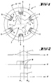
- the reluctance motor 1 shown in FIG. 1 settles essentially a stator 2 and a rotor 3 together, with pronounced stator and rotor poles 4, 5 in an uneven number.
- Fig. 1 is a typical structure a 6/4-pole motor 1 shown.
- the time measurement can be done in the simplest way by a Microcontroller control can be realized. To do this an internal counter when the voltage U is switched on started and when the maximum current is exceeded I Max stopped.
Landscapes
- Engineering & Computer Science (AREA)
- Power Engineering (AREA)
- Control Of Electric Motors In General (AREA)
- Synchronous Machinery (AREA)
Description
- Fig. 1
- einen schematisch dargestellten Reluktanzmotor mit einem Rotor und einem Stator;
- Fig. 2
- Kennlinien des Reluktanzmotors in unbelastetem Zustand desselben, die Induktivität, die Momente und den Strom in Abhängigkeit von der Winkelstellung zwischen Rotor und Stator betreffend;
- Fig. 3
- eine der Fig. 2 entsprechende Kennliniendarstellung, jedoch bei Belastung des Reluktanzmotors;
- Fig. 4
- Kennlinien zur Darstellung des Verlaufs einer Spannung an einer Spule und des daraus resultierenden Spulenstromes,
- Fig. 5
- zwei in Zeitabhängigkeit dargestellte Stromkennlinien, ohne und mit Belastung des Reluktanzmotors;
- Fig. 6
- eine weitere in Zeitabhängigkeit dargestellte Stromkennlinie;
- Fig. 7
- ein Schaltbild für eine beispielhafte Stromerfassung;
- Fig. 8
- zwei in Zeitabhängigkeit dargestellte Stromkennlinien mit zwei unterschiedlichen vordefinierten Stromwerten;
- Fig. 9
- ein Schaltbild für eine Ansteuerung von drei Reluktanzmotoren durch einen gemeinsamen Umrichter.
Es ist zu erkennen, daß die Stromeinspeisung zu gleichen Winkeln Alpha 1 und Alpha 2 beidseitig des Wendepunktes, welcher der genauen Gegenüberlage von Rotorpol 5 und Statorpol 4 entspricht, erfolgt.
Der Strom I in der Statorspule 6 wird nach dem Pulsweitenmodulationsverfahren gesteuert. Bei diesem Verfahren werden die Spulen 6 abwechselnd auf eine positive und negative konstante Spannung U geschaltet. Der Strom I erhöht sich mit der positiven Spannung und senkt sich umgekehrt mit der negativen Spannung ab. Aus dem Taktverhältnis zwischen Stromerhöhung und -absenkung ergibt sich die resultierende gewünschte Stromhöhe in der jeweiligen Spule 6. In Fig. 4 ist ein typischer Verlauf der Spannung U an einer Spule 6 und des daraus resultierenden Spulenstromes I in Abhängigkeit von der Zeit t dargestellt.
Die Stromerfassung erfolgt über einen Schwellwertschalter, welcher, wie beschrieben durch einen Widerstand und einen Transistor realisiert sein kann.
Claims (9)
- Verfahren zur Steuerung eines Reluktanzmotors (1) mit einem Rotor (3) und einem Stator (2), wobei der Stator (2) einzelne Statorspulen (6) aufweist und je nach Belastung des Motors (1) ein vordefinierter Strom (I) in eine Spule (6) fließt, wobei weiter der vordefinierte Strom (I) aus der Aufprägung einer konstanten Spannung (U) resultiert, dadurch gekennzeichnet, dass bei Aufprägung der Spannung (U) die Zeit (t1, t2) bis zum Erreichen des maximalen Stromwertes (I Max) gemessen wird, dass die gemessene Zeit (t1, t2) als Maß der Belastung des Motors herangezogen wird und dass der vordefinierte Strom (I) durch Aus- und Einschalten der konstanten Spannung (U) beibehalten wird, wobei die Spannung (U) positiv ist und so lange auf die Spule geschaltet ist, bis der maximale Stromwert (I Max) überschritten wird und danach die Aus- und Einschaltung erfolgt, um den vordefinierten Strom zu halten.
- Verfahren nach Anspruch 1, dadurch gekennzeichnet, dass bei Erreichen eines Grenzstromes (IGrenz) zur Verhinderung einer Motorüberlastung eine Drehzahlverringerung vorgenommen wird.
- Verfahren nach einem der vorhergehenden Ansprüche, dadurch gekennzeichnet, dass die Zeitmessung durch Starten (Z1) eines internen Zählers beim Einschalten der Spannung (U) und Anhalten (Z2) des Zählers bei Überschreiten eines maximalen Stromwertes (IMax) vorgenommen wird.
- Verfahren nach Anspruch 3, dadurch gekennzeichnet, dass, ausgelöst durch Erreichen eines Minimal-Zählerwertes, eine Drehzahlreduzierung gesteuert wird.
- Verfahren nach einem der vorhergehenden Ansprüche, dadurch gekennzeichnet, dass eine Steuerung der Statorströme abhängig von der gemessenen Zeit (t1, t2) erfolgt.
- Verfahren nach einem der vorhergehenden Ansprüche, dadurch gekennzeichnet, dass der vordefinierte Strom (I) veränderbar ist.
- Verfahren nach Anspruch 6, dadurch gekennzeichnet, dass der vordefinierte Strom (I) stufenlos veränderbar ist.
- Verfahren nach einem der vorhergehenden Ansprüche, dadurch gekennzeichnet, dass die Steuerung der Statorströme mittels eines Umrichters (7) erfolgt.
- Verfahren nach Anspruch 8, dadurch gekennzeichnet, dass von dem Umrichter (7) mehrere drehzahlsynchrone Reluktanzmotoren (1', 1", 1''') angesteuert werden.
Applications Claiming Priority (5)
| Application Number | Priority Date | Filing Date | Title |
|---|---|---|---|
| DE19725113 | 1997-06-13 | ||
| DE19725113 | 1997-06-13 | ||
| DE19825926A DE19825926A1 (de) | 1997-06-13 | 1998-06-10 | Reluktanzmotor |
| DE19825926 | 1998-06-10 | ||
| PCT/EP1998/003538 WO1998057419A1 (de) | 1997-06-13 | 1998-06-12 | Reluktanzmotor |
Publications (2)
| Publication Number | Publication Date |
|---|---|
| EP0988689A1 EP0988689A1 (de) | 2000-03-29 |
| EP0988689B1 true EP0988689B1 (de) | 2004-05-06 |
Family
ID=26037424
Family Applications (1)
| Application Number | Title | Priority Date | Filing Date |
|---|---|---|---|
| EP98936329A Expired - Lifetime EP0988689B1 (de) | 1997-06-13 | 1998-06-12 | Reluktanzmotor |
Country Status (8)
| Country | Link |
|---|---|
| EP (1) | EP0988689B1 (de) |
| AT (1) | ATE266273T1 (de) |
| AU (1) | AU8537398A (de) |
| CZ (1) | CZ296265B6 (de) |
| ES (1) | ES2216300T3 (de) |
| PL (1) | PL187196B1 (de) |
| SK (1) | SK285633B6 (de) |
| WO (1) | WO1998057419A1 (de) |
Family Cites Families (2)
| Publication number | Priority date | Publication date | Assignee | Title |
|---|---|---|---|---|
| GB9120404D0 (en) * | 1991-09-25 | 1991-11-06 | Switched Reluctance Drives Ltd | Control of switched reluctance machines |
| US5525887A (en) * | 1995-03-14 | 1996-06-11 | A. O. Smith Corporation | Switched reluctance motor providing rotor position detection at low speeds without a separate rotor shaft position sensor |
-
1998
- 1998-06-12 AT AT98936329T patent/ATE266273T1/de not_active IP Right Cessation
- 1998-06-12 PL PL98337238A patent/PL187196B1/pl unknown
- 1998-06-12 EP EP98936329A patent/EP0988689B1/de not_active Expired - Lifetime
- 1998-06-12 AU AU85373/98A patent/AU8537398A/en not_active Abandoned
- 1998-06-12 WO PCT/EP1998/003538 patent/WO1998057419A1/de not_active Ceased
- 1998-06-12 CZ CZ0406999A patent/CZ296265B6/cs not_active IP Right Cessation
- 1998-06-12 ES ES98936329T patent/ES2216300T3/es not_active Expired - Lifetime
- 1998-06-12 SK SK1601-99A patent/SK285633B6/sk unknown
Also Published As
| Publication number | Publication date |
|---|---|
| ES2216300T3 (es) | 2004-10-16 |
| WO1998057419A1 (de) | 1998-12-17 |
| CZ296265B6 (cs) | 2006-02-15 |
| EP0988689A1 (de) | 2000-03-29 |
| AU8537398A (en) | 1998-12-30 |
| SK285633B6 (sk) | 2007-05-03 |
| PL337238A1 (en) | 2000-08-14 |
| PL187196B1 (pl) | 2004-05-31 |
| SK160199A3 (en) | 2000-08-14 |
| CZ9904069A3 (cs) | 2000-10-11 |
| ATE266273T1 (de) | 2004-05-15 |
Similar Documents
| Publication | Publication Date | Title |
|---|---|---|
| DE4124240C2 (de) | Verfahren zur Regelung des Motorstroms eines bürstenlosen Gleichstommotors | |
| DE69518553T2 (de) | Vorrichtung zur Leistungserzeugung für Fahrzeuge | |
| EP0803465B1 (de) | Einrichtung zur Erfassung der momentanen Belastung und/oder der Dauerbeanspruchung von Fördermitteln, insbesondere von Hubwerken | |
| DE3779752T2 (de) | Motorerregungsschaltung. | |
| DE19956104A1 (de) | Sensorlose Erfassung eines festgestellten Rotors eines Motors mit geschalteter Reluktanz | |
| DE69830958T2 (de) | System und Verfahren zum Bremsen eines Stellantriebes mit einem bürstenlosen Motor | |
| DE19843924A1 (de) | Berührungslose Steuerung eines Motors mit geschalteter Reluktanz | |
| EP1514342B1 (de) | Verfahren und schaltungsanordnung zum betreiben von schrittmotoren | |
| DE102004055073A1 (de) | Überlastschutz für Gleichstrommotoren | |
| EP0771065B1 (de) | Verfahren zum Anlaufen drehzahlveränderlicher elektrischer Antriebe | |
| EP0397818B1 (de) | Verfahren und einrichtung zur änderung der ist-drehzahl eines mehrphasen-asynchronmotors, und zur ausführung des verfahrens geeignetes motorensystem | |
| DE19946050A1 (de) | Verfahren zur Drehzahlregelung für geschaltete Reluktanzmotoren (GRM) | |
| DE3044027C2 (de) | Stromregler für einen Gleichstrommotor | |
| DE4026366C2 (de) | ||
| DE19825926A1 (de) | Reluktanzmotor | |
| DE2938625A1 (de) | Schaltungsanordnung zum energiesparen | |
| DE2414721C3 (de) | Verfahren zur Steuerung der Drehzahl- bzw. Geschwindigkeit einer frequenzumrichtergespeisten Drehstrom-Asynchronmaschine | |
| EP0993697B1 (de) | Elektromotor und verfahren zum betreiben eines elektromotors | |
| DE3409299C2 (de) | Ein- oder mehrphasiger Wechselstromsteller mit Impulsbreitensteuerung | |
| EP0988689A1 (de) | Reluktanzmotor | |
| DE19619190C1 (de) | Bremssteuervorrichtung für den Fahrantrieb eines Flurförderzeugs für höhere Fahrgeschwindigkeiten | |
| DE102020106106A1 (de) | Elektromotor sowie Ansteuerungsverfahren | |
| DE4410959C2 (de) | Verfahren zum Anlassen eines Schleifringläufermotors | |
| DE2829657C2 (de) | Drehzahlbegrenzung für einen Reihenschlußmotor | |
| EP1407536B1 (de) | Verfahren zur gleichmässigen laufsteuerung eines reluktanzmotors und einrichtung zur einschaltstrom begrenzung |
Legal Events
| Date | Code | Title | Description |
|---|---|---|---|
| PUAI | Public reference made under article 153(3) epc to a published international application that has entered the european phase |
Free format text: ORIGINAL CODE: 0009012 |
|
| 17P | Request for examination filed |
Effective date: 19991124 |
|
| AK | Designated contracting states |
Kind code of ref document: A1 Designated state(s): AT BE CH DE DK ES FI FR GB GR IE IT LI NL PT SE |
|
| AX | Request for extension of the european patent |
Free format text: LT PAYMENT 19991124;LV PAYMENT 19991124;SI PAYMENT 19991124 |
|
| 17Q | First examination report despatched |
Effective date: 20001004 |
|
| GRAP | Despatch of communication of intention to grant a patent |
Free format text: ORIGINAL CODE: EPIDOSNIGR1 |
|
| GRAS | Grant fee paid |
Free format text: ORIGINAL CODE: EPIDOSNIGR3 |
|
| GRAA | (expected) grant |
Free format text: ORIGINAL CODE: 0009210 |
|
| AK | Designated contracting states |
Kind code of ref document: B1 Designated state(s): AT BE CH DE DK ES FI FR GB GR IE IT LI NL PT SE |
|
| AX | Request for extension of the european patent |
Extension state: LT LV SI |
|
| PG25 | Lapsed in a contracting state [announced via postgrant information from national office to epo] |
Ref country code: NL Free format text: LAPSE BECAUSE OF FAILURE TO SUBMIT A TRANSLATION OF THE DESCRIPTION OR TO PAY THE FEE WITHIN THE PRESCRIBED TIME-LIMIT Effective date: 20040506 Ref country code: IE Free format text: LAPSE BECAUSE OF FAILURE TO SUBMIT A TRANSLATION OF THE DESCRIPTION OR TO PAY THE FEE WITHIN THE PRESCRIBED TIME-LIMIT Effective date: 20040506 Ref country code: FI Free format text: LAPSE BECAUSE OF FAILURE TO SUBMIT A TRANSLATION OF THE DESCRIPTION OR TO PAY THE FEE WITHIN THE PRESCRIBED TIME-LIMIT Effective date: 20040506 |
|
| REG | Reference to a national code |
Ref country code: GB Ref legal event code: FG4D Free format text: NOT ENGLISH |
|
| REG | Reference to a national code |
Ref country code: CH Ref legal event code: EP |
|
| REF | Corresponds to: |
Ref document number: 59811337 Country of ref document: DE Date of ref document: 20040609 Kind code of ref document: P |
|
| REG | Reference to a national code |
Ref country code: IE Ref legal event code: FG4D Free format text: GERMAN |
|
| PG25 | Lapsed in a contracting state [announced via postgrant information from national office to epo] |
Ref country code: LI Free format text: LAPSE BECAUSE OF NON-PAYMENT OF DUE FEES Effective date: 20040630 Ref country code: CH Free format text: LAPSE BECAUSE OF NON-PAYMENT OF DUE FEES Effective date: 20040630 Ref country code: BE Free format text: LAPSE BECAUSE OF NON-PAYMENT OF DUE FEES Effective date: 20040630 |
|
| REG | Reference to a national code |
Ref country code: CH Ref legal event code: NV Representative=s name: R. A. EGLI & CO. PATENTANWAELTE |
|
| PG25 | Lapsed in a contracting state [announced via postgrant information from national office to epo] |
Ref country code: SE Free format text: LAPSE BECAUSE OF FAILURE TO SUBMIT A TRANSLATION OF THE DESCRIPTION OR TO PAY THE FEE WITHIN THE PRESCRIBED TIME-LIMIT Effective date: 20040806 Ref country code: GR Free format text: LAPSE BECAUSE OF FAILURE TO SUBMIT A TRANSLATION OF THE DESCRIPTION OR TO PAY THE FEE WITHIN THE PRESCRIBED TIME-LIMIT Effective date: 20040806 Ref country code: DK Free format text: LAPSE BECAUSE OF FAILURE TO SUBMIT A TRANSLATION OF THE DESCRIPTION OR TO PAY THE FEE WITHIN THE PRESCRIBED TIME-LIMIT Effective date: 20040806 |
|
| GBT | Gb: translation of ep patent filed (gb section 77(6)(a)/1977) |
Effective date: 20040803 |
|
| REG | Reference to a national code |
Ref country code: ES Ref legal event code: FG2A Ref document number: 2216300 Country of ref document: ES Kind code of ref document: T3 |
|
| LTIE | Lt: invalidation of european patent or patent extension |
Effective date: 20040506 |
|
| NLV1 | Nl: lapsed or annulled due to failure to fulfill the requirements of art. 29p and 29m of the patents act | ||
| ET | Fr: translation filed | ||
| REG | Reference to a national code |
Ref country code: IE Ref legal event code: FD4D |
|
| BERE | Be: lapsed |
Owner name: VORWERK & CO. INTERHOLDING G.M.B.H. Effective date: 20040630 |
|
| REG | Reference to a national code |
Ref country code: CH Ref legal event code: PL |
|
| PLBE | No opposition filed within time limit |
Free format text: ORIGINAL CODE: 0009261 |
|
| STAA | Information on the status of an ep patent application or granted ep patent |
Free format text: STATUS: NO OPPOSITION FILED WITHIN TIME LIMIT |
|
| 26N | No opposition filed |
Effective date: 20050208 |
|
| PGFP | Annual fee paid to national office [announced via postgrant information from national office to epo] |
Ref country code: GB Payment date: 20060605 Year of fee payment: 9 |
|
| REG | Reference to a national code |
Ref country code: HK Ref legal event code: WD Ref document number: 1026984 Country of ref document: HK |
|
| PGFP | Annual fee paid to national office [announced via postgrant information from national office to epo] |
Ref country code: AT Payment date: 20070605 Year of fee payment: 10 |
|
| PG25 | Lapsed in a contracting state [announced via postgrant information from national office to epo] |
Ref country code: PT Free format text: LAPSE BECAUSE OF NON-PAYMENT OF DUE FEES Effective date: 20041006 |
|
| GBPC | Gb: european patent ceased through non-payment of renewal fee |
Effective date: 20070612 |
|
| PG25 | Lapsed in a contracting state [announced via postgrant information from national office to epo] |
Ref country code: GB Free format text: LAPSE BECAUSE OF NON-PAYMENT OF DUE FEES Effective date: 20070612 |
|
| PG25 | Lapsed in a contracting state [announced via postgrant information from national office to epo] |
Ref country code: AT Free format text: LAPSE BECAUSE OF NON-PAYMENT OF DUE FEES Effective date: 20080612 |
|
| PGFP | Annual fee paid to national office [announced via postgrant information from national office to epo] |
Ref country code: IT Payment date: 20120626 Year of fee payment: 15 |
|
| PG25 | Lapsed in a contracting state [announced via postgrant information from national office to epo] |
Ref country code: IT Free format text: LAPSE BECAUSE OF NON-PAYMENT OF DUE FEES Effective date: 20130612 |
|
| REG | Reference to a national code |
Ref country code: FR Ref legal event code: PLFP Year of fee payment: 19 |
|
| REG | Reference to a national code |
Ref country code: FR Ref legal event code: PLFP Year of fee payment: 20 |
|
| PGFP | Annual fee paid to national office [announced via postgrant information from national office to epo] |
Ref country code: FR Payment date: 20170621 Year of fee payment: 20 Ref country code: DE Payment date: 20170621 Year of fee payment: 20 |
|
| PGFP | Annual fee paid to national office [announced via postgrant information from national office to epo] |
Ref country code: ES Payment date: 20170703 Year of fee payment: 20 |
|
| REG | Reference to a national code |
Ref country code: DE Ref legal event code: R071 Ref document number: 59811337 Country of ref document: DE |
|
| REG | Reference to a national code |
Ref country code: ES Ref legal event code: FD2A Effective date: 20200723 |
|
| PG25 | Lapsed in a contracting state [announced via postgrant information from national office to epo] |
Ref country code: ES Free format text: LAPSE BECAUSE OF EXPIRATION OF PROTECTION Effective date: 20180613 |