EP0989030A2 - Verfahren zur Herstellung eines Hitzeschildes und ein mit diesem Verfahren hergestelltes Hitzeschild - Google Patents
Verfahren zur Herstellung eines Hitzeschildes und ein mit diesem Verfahren hergestelltes Hitzeschild Download PDFInfo
- Publication number
- EP0989030A2 EP0989030A2 EP99116402A EP99116402A EP0989030A2 EP 0989030 A2 EP0989030 A2 EP 0989030A2 EP 99116402 A EP99116402 A EP 99116402A EP 99116402 A EP99116402 A EP 99116402A EP 0989030 A2 EP0989030 A2 EP 0989030A2
- Authority
- EP
- European Patent Office
- Prior art keywords
- insulating material
- plate
- compressed
- insulating
- heat shield
- Prior art date
- Legal status (The legal status is an assumption and is not a legal conclusion. Google has not performed a legal analysis and makes no representation as to the accuracy of the status listed.)
- Withdrawn
Links
Images

Classifications
-
- B—PERFORMING OPERATIONS; TRANSPORTING
- B60—VEHICLES IN GENERAL
- B60R—VEHICLES, VEHICLE FITTINGS, OR VEHICLE PARTS, NOT OTHERWISE PROVIDED FOR
- B60R13/00—Elements for body-finishing, identifying, or decorating; Arrangements or adaptations for advertising purposes
- B60R13/08—Insulating elements, e.g. for sound insulation
- B60R13/0869—Insulating elements, e.g. for sound insulation for protecting heat sensitive parts, e.g. electronic components
-
- Y—GENERAL TAGGING OF NEW TECHNOLOGICAL DEVELOPMENTS; GENERAL TAGGING OF CROSS-SECTIONAL TECHNOLOGIES SPANNING OVER SEVERAL SECTIONS OF THE IPC; TECHNICAL SUBJECTS COVERED BY FORMER USPC CROSS-REFERENCE ART COLLECTIONS [XRACs] AND DIGESTS
- Y10—TECHNICAL SUBJECTS COVERED BY FORMER USPC
- Y10T—TECHNICAL SUBJECTS COVERED BY FORMER US CLASSIFICATION
- Y10T29/00—Metal working
- Y10T29/30—Foil or other thin sheet-metal making or treating
- Y10T29/301—Method
- Y10T29/303—Method with assembling or disassembling of a pack
-
- Y—GENERAL TAGGING OF NEW TECHNOLOGICAL DEVELOPMENTS; GENERAL TAGGING OF CROSS-SECTIONAL TECHNOLOGIES SPANNING OVER SEVERAL SECTIONS OF THE IPC; TECHNICAL SUBJECTS COVERED BY FORMER USPC CROSS-REFERENCE ART COLLECTIONS [XRACs] AND DIGESTS
- Y10—TECHNICAL SUBJECTS COVERED BY FORMER USPC
- Y10T—TECHNICAL SUBJECTS COVERED BY FORMER US CLASSIFICATION
- Y10T29/00—Metal working
- Y10T29/49—Method of mechanical manufacture
- Y10T29/4935—Heat exchanger or boiler making
-
- Y—GENERAL TAGGING OF NEW TECHNOLOGICAL DEVELOPMENTS; GENERAL TAGGING OF CROSS-SECTIONAL TECHNOLOGIES SPANNING OVER SEVERAL SECTIONS OF THE IPC; TECHNICAL SUBJECTS COVERED BY FORMER USPC CROSS-REFERENCE ART COLLECTIONS [XRACs] AND DIGESTS
- Y10—TECHNICAL SUBJECTS COVERED BY FORMER USPC
- Y10T—TECHNICAL SUBJECTS COVERED BY FORMER US CLASSIFICATION
- Y10T29/00—Metal working
- Y10T29/49—Method of mechanical manufacture
- Y10T29/4935—Heat exchanger or boiler making
- Y10T29/49366—Sheet joined to sheet
-
- Y—GENERAL TAGGING OF NEW TECHNOLOGICAL DEVELOPMENTS; GENERAL TAGGING OF CROSS-SECTIONAL TECHNOLOGIES SPANNING OVER SEVERAL SECTIONS OF THE IPC; TECHNICAL SUBJECTS COVERED BY FORMER USPC CROSS-REFERENCE ART COLLECTIONS [XRACs] AND DIGESTS
- Y10—TECHNICAL SUBJECTS COVERED BY FORMER USPC
- Y10T—TECHNICAL SUBJECTS COVERED BY FORMER US CLASSIFICATION
- Y10T29/00—Metal working
- Y10T29/49—Method of mechanical manufacture
- Y10T29/49826—Assembling or joining
-
- Y—GENERAL TAGGING OF NEW TECHNOLOGICAL DEVELOPMENTS; GENERAL TAGGING OF CROSS-SECTIONAL TECHNOLOGIES SPANNING OVER SEVERAL SECTIONS OF THE IPC; TECHNICAL SUBJECTS COVERED BY FORMER USPC CROSS-REFERENCE ART COLLECTIONS [XRACs] AND DIGESTS
- Y10—TECHNICAL SUBJECTS COVERED BY FORMER USPC
- Y10T—TECHNICAL SUBJECTS COVERED BY FORMER US CLASSIFICATION
- Y10T428/00—Stock material or miscellaneous articles
- Y10T428/23—Sheet including cover or casing
-
- Y—GENERAL TAGGING OF NEW TECHNOLOGICAL DEVELOPMENTS; GENERAL TAGGING OF CROSS-SECTIONAL TECHNOLOGIES SPANNING OVER SEVERAL SECTIONS OF THE IPC; TECHNICAL SUBJECTS COVERED BY FORMER USPC CROSS-REFERENCE ART COLLECTIONS [XRACs] AND DIGESTS
- Y10—TECHNICAL SUBJECTS COVERED BY FORMER USPC
- Y10T—TECHNICAL SUBJECTS COVERED BY FORMER US CLASSIFICATION
- Y10T428/00—Stock material or miscellaneous articles
- Y10T428/23—Sheet including cover or casing
- Y10T428/237—Noninterengaged fibered material encased [e.g., mat, batt, etc.]
- Y10T428/238—Metal cover or casing
-
- Y—GENERAL TAGGING OF NEW TECHNOLOGICAL DEVELOPMENTS; GENERAL TAGGING OF CROSS-SECTIONAL TECHNOLOGIES SPANNING OVER SEVERAL SECTIONS OF THE IPC; TECHNICAL SUBJECTS COVERED BY FORMER USPC CROSS-REFERENCE ART COLLECTIONS [XRACs] AND DIGESTS
- Y10—TECHNICAL SUBJECTS COVERED BY FORMER USPC
- Y10T—TECHNICAL SUBJECTS COVERED BY FORMER US CLASSIFICATION
- Y10T428/00—Stock material or miscellaneous articles
- Y10T428/23—Sheet including cover or casing
- Y10T428/239—Complete cover or casing
Definitions
- the invention relates to a method for manufacturing a heat shield and one using this method manufactured heat shield according to the generic term of Claim 1.
- Such heat shields are everywhere wherever temperature-sensitive units are required, Components or connecting lines in a way must be protected that heat radiation is not can hit them directly. This is particularly so in the case of motor vehicles, where hot parts of the Drive unit in close proximity arranged to further temperature-sensitive units are.
- a heat shield is known from DE 38 34 054 C2, at least for the shielding from heat radiation two flat materials are used, the at least two edge regions facing away from each other are interconnected.
- the flat materials mentioned are connected so that between a gap is formed for them.
- that facing the heat radiation source Flat material through a predetermined profile or beading or appropriate material selection in their expansion characteristics is so oriented that it is towards the heat source.
- Appropriate training is intended to make an adjustment to the heat load that occurs as the distance increases at higher temperatures of the two flat materials used, preferably consist of sheet metal, enlarged and a enlarged air gap that naturally occurs improves the isolation effect.
- This heat shield can continue with respect to the Isolation effect can be improved if on the Inner surfaces of the flat materials proposed there additionally a thermal insulation layer applied becomes.
- Organic ones are particularly suitable for this or inorganic fiber materials, however also metal mesh, knitted fabrics or expanded metal. This continue to improve the sound insulation by this heat shield is also achieved.
- this heat shield has the disadvantage that not every contour of the heat shield is formed can be to get the desired effect for adapting to different temperatures too to reach.
- the insulation effect is sole use of an air gap without additional Thermal insulation materials limited.
- thermal insulation materials as a thermal insulation layer
- thermal barrier between the two Outer sheets of a heat shield are inserted.
- the one to be inserted as a thermal insulation layer Bind material with a binding agent.
- binders usually have organic components at high temperatures To cause problems. In particular, these are used organic binders ecologically and toxicologically questionable, since it occurs in the emit gases or chemical reactions at high temperatures carry out.
- PCT / DE98 / 00065 therefore describes a method for Manufacture of a heat shield known in which a Binder-free powder and / or flake Insulation material on one of the two as plates molded flat materials is applied and then at least by pressure is solidified in some areas. Then that will second flat material also formed as a plate placed on the insulating material and for example by folding into a shape and / or non-positive connection with the lower flat material brought.
- Advantage of this procedure is that on the use of an ecological or dispensed toxicologically questionable binder can be.
- the disadvantage is that it is loose free-flowing insulating material exactly on the lower one Plate can be applied in the desired distribution got to. For this it is necessary to order the pourable Material on a component of the to be manufactured Apply heat shield exactly. This manufacturing route is therefore complex and expensive.
- a granular, powdery and / or flaky insulating material not compressed or compressed in the desired Shape according to the heat shield to be manufactured shaped and then onto one of the two Outer plates of the heat shield applied. Subsequently the heat shield with the other outer plate provided and both outer plates form and / or with each other non-positively connected. In this way the application of suitable layers of insulating material simplified and more precise on an outer plate.
- the transfer of the preformed insulation material can be done, for example, by a sucker.
- the vacuum cleaner itself has one of the desired shapes appropriate contour, so the shape of the insulating material through the simple suction of the loose material. Is one of the outer panels with openings, so it can the suction device, for example by suction or magnetically, be attached. Then the insulating plate made of loose or compacted material from the suction cup to the surface of the attached outer plate sucked in and together with the outer plate on a second outer plate applied.
- the transportation of the preformed insulation material too The outer panel becomes particularly simple provided it is in front compressed to a coherent insulating plate during transport and only then on one of the two outer panels applied a heat shield to be produced.
- This compacted coherent insulating plate has a certain intrinsic stability, which makes it possible to transport them.
- the second outer plate placed on the insulating plate and with the other outer plate to the invention Composite of two outer panels with a central one Insulating layer connected as a heat shield.
- An advantage of the method according to the invention is that the insulating material has no binder got to. This results in no ecological or toxicological concerns about such a heat shield. Overall, the low binding forces between the individual grains an improved insulation material Sound insulation and lower resonance problems in the heat shield according to the invention.
- the insulating material results in a coherent insulating plate sufficient own strength of the Insulating plate so that it can be transported, for example with a perforated plate level sucker.
- the compaction can be done, for example, by rolling / calendering, Subsequent delivery of the insulating plate on a tape, punching the insulating plate into the desired one Form and handover to the as a means of transport serving suction cups. Alternatively, a plate pressed, punched and handed over to the sucker.
- the compression can also be done by a single Pressing a layer of insulating material of uniform thickness or one with different ones suitable thickness contoured insulating material layer or in several pressing processes with taking place between the individual pressing processes further - also locally limited - order from Insulation material.
- the compression can also be done so that only in some areas the insulation material is compressed and then in the uncompressed areas the insulating material removed, for example is blown away or suctioned off. Let it through any structure, for example with holes for screws etc. Furthermore, the Check the compaction of the material so that bulges, Openings, beads and / or webs in / on the surfaces used for compaction Tool can be generated specifically. Such Bulges and beads or webs can be used for stabilization of the heat shield, for local reinforcement the shielding effect or to save material in Low heat exposure areas can be used.
- a preformed and compressed insulation plate can also by means of a tape to the first outer plate transported and stored on this. This can be done, for example, that at the end of the tape the tape from the coherent insulating plate, for example pulled down over a belt deflection roller and the insulating plate beyond the end of the tape is pushed onto the outer plate.
- the Insulating plate can be created on the tape by for example unexpanded insulating material such as Vermiculite deposited on the belt, deformed, on the Band warms and expands and at the same time or is then pressed.
- Mica are particularly suitable as loose insulating material Mica, expanded mica, unexpanded Graphite, expanded graphite, pearlite or mica degradation products such as vermiculite or expanded vermiculite.
- it can be unexpanded Insulating material, for example unexpanded Graphite or unexpanded vermiculite, on a Press plate applied and by means of the press plate heated and expanded.
- the plate is preheated for this purpose or after the material has been applied, for example to 250 ° C, advantageously Heated to 300 ° C or higher.
- the compression can then during the heating of the insulating material or afterwards.
- the sucker can become a transported further flat plate and there in the for example, given by the suction cup outer Form compressed into an insulating plate and then applied to one of the outer plates of the heat shield become.
- an insulating material for the process described above are particularly suitable for mica, expanded mica, unexpanded graphite, expanded graphite, Pearlite or mica degradation products such as Vermiculite or expanded vermiculite.
- This advantageously has a grain size of up to 10 mm, preferably between 1 and 3 mm.
- the insulation material can also have finer fractions.
- the one used for the production of the insulation panels Insulating material can also contain other additives like contain inorganic fibers. Such additives can reduce the strength of the insulating plate improve. Inorganic ones are particularly suitable for this Fibers, preferably with a non-respiratory Diameter> 5 ⁇ m, for example glass fibers or mineral fibers. These are also ecological and toxicologically harmless.
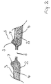
- FIG. 1 shows a heat shield 1 according to the invention.
- This consists of a lower outer plate 2 and an upper outer plate 3.
- the two outer plates 2 and 3 are in the edge area 5 by flanging the Outer edge of the outer plate 3 through the outer edge of the Outer plate 2 firmly connected.
- Between the two outer plates 2 and 3 are one Plate 4 made of the insulating material vermiculite with a Grain size of approx. 1 to 3 mm.
- the heat shield 1 shown in FIG. 1 was produced by expanding vermiculite with a grain from 1 to 3 mm as an undensified layer of insulating material with a thickness between 5 and 7 mm a plate shaped in the desired contour was applied.
- the material was dosed via a doctor blade system with an elongated hole funnel. This can also with a conveyor belt / brush system) or medium done a metering roller with brush surface. Excess material fell past the plate. Then the vermiculite was reduced by a factor 8 compressed.
- another flat sheet 2 with the dimension of the insulating plate on the insulating plate 4 hung up.
- the lower sheet 2 serves as lower outer plate 2 and is finally around the Edge of the upper acting as the upper outer plate 3 Sheets folded over.
- FIG. 2 shows a further heat shield according to the invention 1.
- a lower ancestral plate 2 and an upper outer plate 3 close an insulating plate 4 a.
- the lower outer plate 2 and the upper outer plate 3 are merged in area 6, in the a hole for example for the implementation of a Screw in the lower outer plate 2 and the upper outer plate 3 is provided.
- the upper one Outer plate 3 bulged so that there is a local increased distance between the two outer plates 2 and 3 results.
- the insulating plate 4 has a greater thickness.
- This accumulation of material in area 7 causes one significantly increased thermal and acoustic insulation in the the through opening in area 6 surrounding area 7. This is particularly advantageous because the heat and sound insulation in area 6 due to the lack of insulating material is reduced and therefore in the immediately adjacent area 7 Compensation is created.
- this heat shield 1 The procedure for producing this heat shield 1 is as follows: that first the two outer plates 2 and 3 with the corresponding through opening in area 6 getting produced. The outer panels 2 and 3 are already according to their final form including the bulges formed in area 7. Then an insulating plate is made Vermiculite with a grain size of 1 to 3 mm by a factor of 5 condensed. The compression takes place by pressing in a mold so that the vermiculite plate 4th already the shape shown in Fig. 2 with the thickening in area 7 and the recess in the area 6 has. Then this plate 4 through a suction cup designed as a perforated plate and on the outer plate 2 in the correct positioning hung up. Then the upper outer plate 3 on the Insulating plate 4 placed and with the lower outer plate 2 connected in the manner described in Fig. 1.
Landscapes
- Physics & Mathematics (AREA)
- Acoustics & Sound (AREA)
- Engineering & Computer Science (AREA)
- Mechanical Engineering (AREA)
- Thermal Insulation (AREA)
- Exhaust Silencers (AREA)
- Laminated Bodies (AREA)
- Building Environments (AREA)
- Gasket Seals (AREA)
Abstract
Description
- Fig. 1
- ein erfindungsgemäßes Hitzeschild und
- Fig. 2
- ein weiteres erfindungsgemäßes Hitzeschild.
Claims (29)
- Verfahren zur Herstellung eines Hitzeschildes (1) zur Verwendung in Kraftfahrzeugen, bestehend aus einem Isoliermaterial (4), das zwischen zwei zumindest teilweise plastisch verformbaren Außenplatten (2, 3) aufgenommen ist, wobei körner-, pulver- und/oder blättchenförmiges binderfreies Isoliermaterial (4) auf eine (2) der beiden Außenplatten diese zumindest teilweise überdeckend aufgebracht wird und die zweite Außenplatte (3) in oberhalb des Isoliermaterials (4) liegender Position mit der ersten Außenplatte (2) durch eine form- und/oder kraftschlüssige Verbindung der Außenplatten (2,3) an geeigneten Stellen wie z.B. in deren Randbereichen (5) verbunden wird,
dadurch gekennzeichnet,
daß das Isoliermaterial (4) in einer gewünschten Kontur als Isolierplatte geformt und anschließend in dieser Kontur auf eine (2) der beiden Außenplatten diese zumindest teilweise überdeckend aufgebracht wird. - Verfahren nach Anspruch 1,
dadurch gekennzeichnet, daß das Isoliermaterial unverdichtet auf eine der beiden Außenplatten aufgebracht wird und gegebenenfalls anschließend verdichtet wird. - Verfahren nach Anspruch 2,
dadurch gekennzeichnet, daß das Isoliermaterial (4) als Schicht erzeugt, von einem flächigen Sauger aufgenommen und durch Pressung verdichtet wird. - Verfahren nach Anspruch 2 oder 3,
dadurch gekennzeichnet, daß das Isoliermaterial durch einen Sauger mit einer Kontur entsprechend der gewünschten Kontur der Isolierplatte aufgenommen wird. - Verfahren nach mindestens einem der Ansprüche 2 bis 4,
dadurch gekennzeichnet, daß das Isoliermaterial durch einen Sauger auf eine der Außenplatten aufgebracht und das Isoliermaterial von dem Sauger selbst oder durch eine Preßplatte oder durch Andrücken der anderen Außenplatte verdichtet wird. - Verfahren nach Anspruch 1,
dadurch gekennzeichnet, daß das Isoliermaterial (4) vor dem Aufbringen auf eine (2) der beiden Außenplatten zu einer kohärenten Isolierplatte verdichtet wird. - Verfahren nach Anspruch 6,
dadurch gekennzeichnet, daß das Isoliermaterial (4) in einer an die Konturen der Außenplatten angepaßten Form verdichtet wird. - Verfahren nach Anspruch 6 oder 7,
dadurch gekennzeichnet, daß das Isoliermaterial (4) durch Walzen/Kalandrieren, gegebenenfalls mit einer Prägewalze in der gewünschten Form, verdichtet wird. - Verfahren nach mindestens einem der Ansprüche 6 bis 8,
dadurch gekennzeichnet, daß die Isolierplatte nach der Verdichtung in der gewünschten Form ausgestanzt wird. - Verfahren nach mindestens einem der Ansprüche 6 bis 9,
dadurch gekennzeichnet, daß die Isolierplatte von einem Sauger aufgenommen und auf eine der Außenplatten aufgelegt wird. - Verfahren nach mindestens einem der vorhergehenden Ansprüche,
dadurch gekennzeichnet, daß das Isoliermaterial um einen Faktor bis zu 20, vorzugsweise um einen Faktor 5 bis 10 verdichtet wird. - Verfahren nach mindestens einem der vorhergehenden Ansprüche, daß an einem Sauger eine Außenplatte, die Durchbrechungen aufweist, beispielsweise durch Ansaugen an dem Sauger oder magnetisch befestigt wird, und die Isolierplatte anschließend von dem Sauger angesaugt, aufgenommen und mitsamt der Außenplatte auf die zweite Außenplatte aufgebracht wird.
- Verfahren nach mindestens einem der vorhergehenden Ansprüche,
dadurch gekennzeichnet, daß die Verdichtung durch einen einzigen Preßvorgang erzeugt wird. - Verfahren nach mindestens einem der vorhergehenden Ansprüche,
dadurch gekennzeichnet, daß die Verdichtung des Isoliermaterials (4) in mehreren Preßvorgängen, gegebenenfalls mit weiterem, auch lokal begrenztem Auftrag von Isoliermaterial zwischen den einzelnen Preßvorgängen, erfolgt. - Verfahren nach mindestens einem der vorhergehenden Ansprüche,
dadurch gekennzeichnet, daß das Isoliermaterial (4) in oder auf einer Form verdichtet wird. - Verfahren nach mindestens einem der vorhergehenden Ansprüche,
dadurch gekennzeichnet, daß gegebenenfalls mit lokal unterschiedlichen Dicken und/oder Dichten verdichtet wird. - Verfahren nach mindestens einem der vorhergehenden Ansprüche,
dadurch gekennzeichnet, daß das Isoliermaterial (4) nur bereichsweise verdichtet wird und anschließend das in den nicht verdichteten Bereichen vorhandene Isoliermaterial entfernt, vorteilhafterweise weggeblasen oder abgesaugt wird. - Verfahren nach mindestens einem der vorhergehenden Ansprüche,
dadurch gekennzeichnet, daß die Verdichtung des Isoliermaterials (4) durch Ausbuchtungen, Öffnungen, Sicken und/oder Stegen in/an den zum Verdichten verwendeten Oberflächen eines Preßwerkzeuges gezielt beeinflußt wird. - Verfahren nach mindestens einem der vorhergehenden Ansprüche,
dadurch gekennzeichnet, daß als Isoliermaterial (4) Glimmer expandierter Glimmer, nicht-expandiertes Graphit, expandiertes Graphit, Perlit oder ein Glimmerabbauprodukt wie Vermiculit oder expandierter Vermiculit verwendet wird. - Verfahren nach mindestens einem der vorhergehenden Ansprüche,
dadurch gekennzeichnet, daß ein Isoliermaterial (4) mit einer Körnung bis zu 10 mm, vorzugsweiwe zwischen 1 mm und 3 mm verwendet wird. - Verfahren nach mindestens einem der vorhergehenden Ansprüche,
dadurch gekennzeichnet, daß als Isoliermaterial ein Material verwendet wird, das weitere Zusatzstoffe wie anorganische Fasern, vorzugsweise mit einem Durchmesser > 5 µm, enthält. - Verfahren nach mindestens einem der vorhergehenden Ansprüche,
dadurch gekennzeichnet, daß die zu verdichtende Schicht aus Isoliermaterial (4) eine Dicke zwische 0,5 mm und 30 mm, vorzugsweise zwischen 5 mm und 8 mm aufweist. - Verfahren nach mindestens einem der vorhergehenden Ansprüche,
dadurch gekennzeichnet, daß die beiden Außenplatten (2, 3) durch zumindest teilweises Umbördeln am Rand (5) verbunden werden. - Verfahren nach mindestens einem der vorhergehenden Ansprüche,
dadurch gekennzeichnet, daß das Hitzeschild (1) nach der Verbindung der beiden Außenplatten dreidimensional verformt wird. - Verfahren nach mindestens einem der vorhergehenden Ansprüche,
dadurch gekennzeichnet, daß zum Verdichten nichtexpandiertes Isoliermaterial, vorteilhafterweise nichtexpandiertes Graphit oder nichtexpandiertes Vermiculit, auf eine Preßunterlage aufgebracht wird, wobei die Preßunterlage über die Expansionstemperatur des nichtexpandierten Isolationsmaterials bereits erwärmt ist oder anschließend erwärmt wird, und anschließend die Verdichtung durchgeführt wird. - Verfahren nach Anspruch 25,
dadurch gekennzeichnet, daß die Preßunterlage auf 250 °C oder höher, vorzugsweise 300 °C oder höher, erwärmt ist bzw. wird. - Hitzeschild (1), hergestellt nach einem Verfahren nach mindestens einem der vorhergehenden Ansprüche,
dadurch gekennzeichnet,
daß zwischen zwei form- und/oder kraftschlüssig miteinander verbundenen Außenplatten (2, 3) eine Isolierplatte aus verdichtetem Isoliermaterial (4) angeordnet ist. - Hitzeschild nach Anspruch 27,
dadurch gekennzeichnet, daß die Isolierplatte aus um einen Faktor bis zu 20, vorzugsweise um den Faktor 5 bis 10 verdichtetem Isoliermaterial (4) besteht. - Hitzeschild nach Anspruch 27 oder 28,
dadurch gekennzeichnet, daß das Isoliermaterial (4) Glimmer, expandierter Glimmer, nicht-expantiertes Graphit, expandiertes Graphit, Perlit oder ein Glimmerabbauprodukt wie Vermiculit oder expandiertes Vermiculit ist.
Applications Claiming Priority (2)
| Application Number | Priority Date | Filing Date | Title |
|---|---|---|---|
| DE19839237A DE19839237C2 (de) | 1998-08-28 | 1998-08-28 | Verfahren zur Herstellung eines Hitzeschildes und ein mit diesem Verfahren hergestelltes Hitzeschild |
| DE19839237 | 1998-08-28 |
Publications (2)
| Publication Number | Publication Date |
|---|---|
| EP0989030A2 true EP0989030A2 (de) | 2000-03-29 |
| EP0989030A3 EP0989030A3 (de) | 2001-12-19 |
Family
ID=7879060
Family Applications (1)
| Application Number | Title | Priority Date | Filing Date |
|---|---|---|---|
| EP99116402A Withdrawn EP0989030A3 (de) | 1998-08-28 | 1999-08-20 | Verfahren zur Herstellung eines Hitzeschildes und ein mit diesem Verfahren hergestelltes Hitzeschild |
Country Status (4)
| Country | Link |
|---|---|
| US (1) | US6279229B1 (de) |
| EP (1) | EP0989030A3 (de) |
| CA (1) | CA2281188C (de) |
| DE (1) | DE19839237C2 (de) |
Cited By (1)
| Publication number | Priority date | Publication date | Assignee | Title |
|---|---|---|---|---|
| CN111318613A (zh) * | 2020-02-28 | 2020-06-23 | 武汉科技大学 | 一种钨锡系助熔剂片的制备方法 |
Families Citing this family (8)
| Publication number | Priority date | Publication date | Assignee | Title |
|---|---|---|---|---|
| DE19700628C2 (de) * | 1997-01-10 | 2003-03-20 | Reinz Dichtungs Gmbh | Verfahren zur Herstellung eines Hitzeschildes und ein mit dem Verfahren hergestelltes Hitzeschild |
| US6871701B2 (en) * | 2001-04-09 | 2005-03-29 | The Furukawa Electric Co., Ltd. | Plate-type heat pipe and method for manufacturing the same |
| US7585559B2 (en) * | 2003-06-03 | 2009-09-08 | Intellectual Property Holdings, Llc | Foam barrier heat shield |
| US6933035B1 (en) | 2003-10-09 | 2005-08-23 | Frank C. Wickstrom | Thermal heat shield |
| US7748184B1 (en) * | 2005-02-09 | 2010-07-06 | Intellectual Property Holdings, Llc | Body panel having improved stiffness and method of making |
| DE102005058253B4 (de) * | 2005-12-06 | 2007-10-04 | Federal-Mogul Sealing Systems Gmbh | Schutzschild zur thermischen und akustischen Abschirmung von Bauteilen einer Verbrennungskraftmaschine |
| JP6300835B2 (ja) | 2013-02-22 | 2018-03-28 | インターフェイス パフォーマンス マテリアルズ, インコーポレイテッド | 軽量熱シールド |
| CN112355076A (zh) * | 2020-11-17 | 2021-02-12 | 金川集团股份有限公司 | 一种空心锭的加热方法 |
Family Cites Families (15)
| Publication number | Priority date | Publication date | Assignee | Title |
|---|---|---|---|---|
| DE96338C (de) | ||||
| JPS58181619A (ja) * | 1982-04-16 | 1983-10-24 | Sekisui Koki Seisakusho:Kk | 発泡スチロ−ルの原料ビ−ズの充填方法 |
| AT390094B (de) * | 1984-11-16 | 1990-03-12 | Austria Metall | Schalldaemmende verbundplatte und verfahren zu ihrer herstellung |
| US4996095A (en) * | 1987-07-01 | 1991-02-26 | Vereinigte Aluminum Werke A.G. | Composite material of aluminum and glass fiber mat, method for its production, and method for utilization as insulator for vehicles |
| GB8715471D0 (en) * | 1987-07-01 | 1987-08-05 | Micropore International Ltd | Moulding thermal insulation |
| DE3834054C3 (de) * | 1988-10-06 | 2000-06-15 | Reinz Dichtungs Gmbh | Hitzeschild |
| DE3905871A1 (de) | 1989-02-24 | 1990-08-30 | Reinz Dichtungs Gmbh | Verbundmaterial |
| CH684206A5 (de) * | 1990-11-12 | 1994-07-29 | Matec Holding | Entsorgbarer Hitzeschild. |
| DE4202569C2 (de) * | 1992-01-30 | 1995-09-21 | Porotherm Daemmstoffe Gmbh | Formwerkzeuge zum Pressen von Dämmschalen |
| DE4211409A1 (de) * | 1992-04-04 | 1993-10-07 | Daimler Benz Ag | Selbsttragende, wärme- und schalldämmende Verkleidung für Verbrennungsmotoren von Kraftfahrzeugen |
| GB9217795D0 (en) * | 1992-08-21 | 1992-10-07 | T & N Technology Ltd | Heat shields |
| US5670264A (en) * | 1994-05-10 | 1997-09-23 | Shertech, Inc. | Thermal barrier |
| DE4429104A1 (de) * | 1994-08-17 | 1996-02-22 | Pirchl Gerhard | Verfahren zur Herstellung eines Hitzeschildes und Hitzeschild, welches nach dem Verfahren hergestellt ist |
| US5614285A (en) * | 1994-12-02 | 1997-03-25 | Ceats | Molded panel having a decorative facing and made from a blend of natural and plastic fibers |
| DE19700628C2 (de) | 1997-01-10 | 2003-03-20 | Reinz Dichtungs Gmbh | Verfahren zur Herstellung eines Hitzeschildes und ein mit dem Verfahren hergestelltes Hitzeschild |
-
1998
- 1998-08-28 DE DE19839237A patent/DE19839237C2/de not_active Expired - Lifetime
-
1999
- 1999-07-27 US US09/361,815 patent/US6279229B1/en not_active Expired - Lifetime
- 1999-08-20 EP EP99116402A patent/EP0989030A3/de not_active Withdrawn
- 1999-08-27 CA CA002281188A patent/CA2281188C/en not_active Expired - Fee Related
Cited By (2)
| Publication number | Priority date | Publication date | Assignee | Title |
|---|---|---|---|---|
| CN111318613A (zh) * | 2020-02-28 | 2020-06-23 | 武汉科技大学 | 一种钨锡系助熔剂片的制备方法 |
| CN111318613B (zh) * | 2020-02-28 | 2021-07-02 | 武汉科技大学 | 一种钨锡系助熔剂片的制备方法 |
Also Published As
| Publication number | Publication date |
|---|---|
| US6279229B1 (en) | 2001-08-28 |
| CA2281188A1 (en) | 2000-02-28 |
| CA2281188C (en) | 2008-01-08 |
| DE19839237A1 (de) | 2000-03-02 |
| DE19839237C2 (de) | 2001-06-28 |
| EP0989030A3 (de) | 2001-12-19 |
Similar Documents
| Publication | Publication Date | Title |
|---|---|---|
| EP1861290B1 (de) | Abschirmelement für kraftfahrzeuge | |
| DE19825762A1 (de) | Geformte mehrschichtige Metallfolien-Abschirmstrukturen und Verfahren zu ihrer Herstellung | |
| DE102009040901A1 (de) | Verfahren zum Herstellen von Tragstrukturen in Kraftfahrzeugen | |
| EP1149233A1 (de) | Verfahren zum herstellen eines schallabsorbierenden isolationsteils und ein nach diesem verfahren hergestelltes isolationsteil | |
| DE19700628C2 (de) | Verfahren zur Herstellung eines Hitzeschildes und ein mit dem Verfahren hergestelltes Hitzeschild | |
| DE19839237C2 (de) | Verfahren zur Herstellung eines Hitzeschildes und ein mit diesem Verfahren hergestelltes Hitzeschild | |
| EP1692012B1 (de) | Schallabsorbierendes hitzeschild | |
| WO2013124454A1 (de) | Verfahren zur herstellung einer graphitfolie, eine mit diesem verfarhren hergestellte graphitfolie, und deren verwendung | |
| DE3831363A1 (de) | Verfahren zum biegen von sandwichplatten | |
| DE10024004C2 (de) | Verfahren zur Herstellung eines Bauteils aus Verbundwerkstoff | |
| DE19522798A1 (de) | Verfahren zur Herstellung eines Strahlungsheizkörpers und Strahlungsheizkörper | |
| DE10105976C2 (de) | Verfahren und Vorrichtung zur Herstellung großflächiger Bauelemente aus Faserverbundwerkstoffen | |
| DE10250716C1 (de) | Verfahren zur Herstellung eines porösen, plattenförmigen Metallverbundes | |
| DE3884515T2 (de) | Dichtungsmaterial und Verfahren zur Herstellung desselben durch Verdichten von an einem metallischen Kern verklebten Schichten. | |
| DE3406418A1 (de) | Verfahren zum aufbringen eines abriebbestaendigen und/oder korrosionsbestaendigen ueberzuges auf einem gegenstand mit unregelmaessiger oberflaeche | |
| AT519010B1 (de) | Kfz-Bauteil | |
| WO2024110398A1 (de) | Schutzelement, bauteilsatz und verfahren zur herstellung des schutzelements | |
| DE9211921U1 (de) | In Kraftfahrzeugen zu verwendendes Abschirmelement | |
| DE19915447C2 (de) | Verfahren zur Herstellung eines Aktivkohlefilters sowie Aktivkohlefilter | |
| DE19909046A1 (de) | Mehrschichtenabsorber - Verfahren zu dessen Herstellung und dessen Verwendung | |
| CH706902A2 (de) | Verfahren zur Herstellung faserverstärkter Kunststoffplatten und Vorrichtung dazu. | |
| DE102021206824A1 (de) | Thermal Interface Material, Energiespeicher mit einem Thermal Interface Material und Verfahren zu deren Herstellung | |
| DE3214823C2 (de) | Lüftungsgitter für zur Aufnahme von elektronischen Baugruppen bestimmte Gerätegehäuse | |
| WO1996034398A1 (de) | Glimmerhaltiger werkstoff | |
| EP3613899A1 (de) | Tamperleiste für eine einbaubohle |
Legal Events
| Date | Code | Title | Description |
|---|---|---|---|
| PUAI | Public reference made under article 153(3) epc to a published international application that has entered the european phase |
Free format text: ORIGINAL CODE: 0009012 |
|
| AK | Designated contracting states |
Kind code of ref document: A2 Designated state(s): AT BE CH CY DE DK ES FI FR GB GR IE IT LI LU MC NL PT SE Kind code of ref document: A2 Designated state(s): DE FR GB |
|
| AX | Request for extension of the european patent |
Free format text: AL;LT;LV;MK;RO;SI |
|
| PUAL | Search report despatched |
Free format text: ORIGINAL CODE: 0009013 |
|
| AK | Designated contracting states |
Kind code of ref document: A3 Designated state(s): AT BE CH CY DE DK ES FI FR GB GR IE IT LI LU MC NL PT SE |
|
| AX | Request for extension of the european patent |
Free format text: AL;LT;LV;MK;RO;SI |
|
| RIC1 | Information provided on ipc code assigned before grant |
Free format text: 7B 60R 13/08 A, 7B 60R 13/02 B |
|
| 17P | Request for examination filed |
Effective date: 20020122 |
|
| AKX | Designation fees paid |
Free format text: DE FR GB |
|
| 17Q | First examination report despatched |
Effective date: 20060823 |
|
| STAA | Information on the status of an ep patent application or granted ep patent |
Free format text: STATUS: THE APPLICATION IS DEEMED TO BE WITHDRAWN |
|
| 18D | Application deemed to be withdrawn |
Effective date: 20070104 |