EP0989040A2 - Adaptateur d'un bloc collecteur d'interface électronique destiné à des wagons pour passagers - Google Patents
Adaptateur d'un bloc collecteur d'interface électronique destiné à des wagons pour passagers Download PDFInfo
- Publication number
- EP0989040A2 EP0989040A2 EP99118289A EP99118289A EP0989040A2 EP 0989040 A2 EP0989040 A2 EP 0989040A2 EP 99118289 A EP99118289 A EP 99118289A EP 99118289 A EP99118289 A EP 99118289A EP 0989040 A2 EP0989040 A2 EP 0989040A2
- Authority
- EP
- European Patent Office
- Prior art keywords
- manifold
- passageway
- valve
- relay
- reservoir
- Prior art date
- Legal status (The legal status is an assumption and is not a legal conclusion. Google has not performed a legal analysis and makes no representation as to the accuracy of the status listed.)
- Withdrawn
Links
- 230000005540 biological transmission Effects 0.000 abstract 1
- 238000012360 testing method Methods 0.000 description 6
- OKBJVIVEFXPEOU-UHFFFAOYSA-N 1,2,3-trichloro-4-(2,3,6-trichlorophenyl)benzene Chemical compound ClC1=C(Cl)C(Cl)=CC=C1C1=C(Cl)C=CC(Cl)=C1Cl OKBJVIVEFXPEOU-UHFFFAOYSA-N 0.000 description 2
- 230000007423 decrease Effects 0.000 description 2
- 238000009420 retrofitting Methods 0.000 description 2
- 238000006243 chemical reaction Methods 0.000 description 1
- 238000010586 diagram Methods 0.000 description 1
- 230000009977 dual effect Effects 0.000 description 1
- 238000013022 venting Methods 0.000 description 1
Images


Classifications
-
- B—PERFORMING OPERATIONS; TRANSPORTING
- B60—VEHICLES IN GENERAL
- B60T—VEHICLE BRAKE CONTROL SYSTEMS OR PARTS THEREOF; BRAKE CONTROL SYSTEMS OR PARTS THEREOF, IN GENERAL; ARRANGEMENT OF BRAKING ELEMENTS ON VEHICLES IN GENERAL; PORTABLE DEVICES FOR PREVENTING UNWANTED MOVEMENT OF VEHICLES; VEHICLE MODIFICATIONS TO FACILITATE COOLING OF BRAKES
- B60T17/00—Component parts, details, or accessories of power brake systems not covered by groups B60T8/00, B60T13/00 or B60T15/00, or presenting other characteristic features
- B60T17/04—Arrangements of piping, valves in the piping, e.g. cut-off valves, couplings or air hoses
- B60T17/043—Brake line couplings, air hoses and stopcocks
-
- B—PERFORMING OPERATIONS; TRANSPORTING
- B60—VEHICLES IN GENERAL
- B60T—VEHICLE BRAKE CONTROL SYSTEMS OR PARTS THEREOF; BRAKE CONTROL SYSTEMS OR PARTS THEREOF, IN GENERAL; ARRANGEMENT OF BRAKING ELEMENTS ON VEHICLES IN GENERAL; PORTABLE DEVICES FOR PREVENTING UNWANTED MOVEMENT OF VEHICLES; VEHICLE MODIFICATIONS TO FACILITATE COOLING OF BRAKES
- B60T13/00—Transmitting braking action from initiating means to ultimate brake actuator with power assistance or drive; Brake systems incorporating such transmitting means, e.g. air-pressure brake systems
- B60T13/10—Transmitting braking action from initiating means to ultimate brake actuator with power assistance or drive; Brake systems incorporating such transmitting means, e.g. air-pressure brake systems with fluid assistance, drive, or release
- B60T13/66—Electrical control in fluid-pressure brake systems
- B60T13/665—Electrical control in fluid-pressure brake systems the systems being specially adapted for transferring two or more command signals, e.g. railway systems
Definitions
- This invention relates to railroad braking systems and, more particularly, to air distribution manifolds configured to retrofit existing passenger rail car pneumatic braking systems for electronic braking control.
- Brake systems for railroad passenger cars are commonly operated and controlled by air.
- pneumatic brake systems typically include operator controls, a control airline, dual chamber air tanks having primary control reservoirs and emergency control reservoirs, AB valves with pipe brackets and service/emergency portions, and brake application devices.
- the control airline extends over the entire length of the train and operatively connects with the AB valves of the individual passenger rail cars, and each AB valve operatively connects with the brake applications system of the corresponding car.
- air pressure in the control airline decreases which in turn causes air from the primary control reservoirs of each car to enter the AB valves and activate the braking systems of each car.
- the operator controls determine the pressure drop in the control airline, and the pressure drop in the control airline determines the braking pressure applied by the braking device. The greater the pressure drop in the control airline, the more braking pressure applied by the braking devices.
- Patent Nos. 5,335,974 and 5,813,730 to Klink which are hereby fully incorporated herein by reference, provide an apparatus for retrofitting freight cars with electronic braking controls.
- these devices fail to address the complexity of and redundance designed into passenger railcars.
- the present invention solves the problems mentioned above and provides a distinct advance in the state of the art.
- the invention allows an existing pneumatic brake system to be retrofitted for electronic control.
- a manifold having a plurality of passageways is interposed between two component of an existing pneumatic brake system.
- the two components include passageways which are connected by the manifold passageways.
- the manifold includes electronically controlled valves which operate the brake system and select either electronic or pneumatic control of the brake system.
- the manifold includes three electronically controlled primary valves with operate three pneumatically controlled secondary valves.
- a secondary fill valve is interposed between a manifold control reservoir passageway and a manifold relay passageway to selectively interrupt and permit a flow of pressurized air from a control reservoir through the manifold control reservoir passageway into the manifold relay passageway.
- a primary fill valve is electronically controlled to operate the secondary fill valve.
- a manifold relay valve separates a pipe bracket side from a service valve side of the manifold relay passageway and selectively connects either an electronic control portion or a pneumatic control portion of the service valve side to the pipe bracket side.
- a bypass valve is electronically controlled to operate the manifold relay valve.
- a secondary vent valve is positioned in pneumatic communication with the manifold relay passageway to vent the manifold relay passageway after braking is completed.
- a primary vent valve is electronically controlled to operate the secondary vent valve.
- the primary valves and the bypass valve are preferably solenoid valves, and the secondary valves and the manifold relay valve are preferably pneumatically controlled.
- Primary and secondary emergency fill valve are also provided for emergency braking.
- a volume adding cylinder of approximately 17 cubic inches is pneumatically connected to the manifold relay passageway and is vented, along with the manifold relay passageway, by the vent valves.
- the manifold also includes a plurality of pressure transducers to provide pressure data for control functions, and a pair of speed control orifices control the flow rate of a air from the primary and emergency control reservoirs into the relay passageways.
- FIGs 1 and 2 illustrate a passenger rail car 20 having a pneumatic braking system 22 retrofitted with a preferred electronic interface manifold adapter 24 in accordance with the present invention.
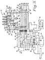
- the braking system 22 includes a pipe bracket 26, a pressurized break pipe 28 (Fig. 3), a service valve 30, and a brake application relay valve 32.
- the manifold 24 is interposed between the pipe bracket 28 and the service valve 30.
- the braking system 22 includes components which are known in the art, and thus, will be included and described to the extent necessary to describe the invention and its operation.
- each passenger rail car has its own braking system which combines with the braking systems of the other rail cars to brake a train. However, the invention will generally be described with reference the braking system of one passenger rail car.
- the pipe bucket 26 includes a plurality of pipe bracket passageways with extend through the pipe bracket. Many of the passageways continue into other components of the braking system, so for convenience and clarity, common passageways extending through multiple components will generally be identified with identical reference numerals.
- a brake line 34 pneumatically connects a breaking device 36 with the brake application relay valve 32, and an emergency vent passageway 38 pneumatically connects the brake pipe 28 with an emergency vent valve 40.
- a main reservoir passageway 42 pneumatically connects a main reservoir 44 with both the relay valve 32 and the manifold 24.
- a second main reservoir passageway 45 is also provided.
- the main reservoir 44 is supplied with air from a main reservoir pipe (not shown) which runs substantially the entire length of the train and is pressurized to approximately 130 psi.
- a relay passageway 46 extends between the relay valve 32 and the manifold 24.
- a primary control reservoir 48 is pneumatically connected to the manifold 24 by a primary reservoir passageway 50, and an emergency control reservoir passageway 52 is in pneumatic communication with an emergency reservoir 54.
- the emergency reservoir passageway 52 pneumatically connects the emergency reservoir 54 with the manifold 24.
- a brake pipe passageway 56 extends between the brake pipe 28 and the manifold 24 and branches of into a brake pipe test line 58 which also extends to the manifold.
- a dirt collector 60 is positioned in the brake pipe passageway 56 between the pipe bracket 26 and the brake pipe 28.
- the pipe bracket also includes an exhaust passageway 62 and a quick service volume 64 with two quick service passageways 66, 68 in pneumatic communication with the quick service volume 64.
- the brake pipe 28 is pressurized and extends from car to car over substantially the entire length of the train.
- the brake pipe 28 connects to the pipe bracket 26 through both the emergency vent passageway 38 and the brake pipe passageway 56.
- the brake pipe is preferably pressurized at approximately 90 psi or approximately 110 psi.
- the service valve 30 includes the main reservoir passageways 42, 45, the primary reservoir passageway 50, the emergency reservoir passageway 52, the break pipe passageway 56, the break pipe test line 58, the exhaust passageway 62, and the quick service passageways 66, 68.
- the service valve also includes a service valve relay passageway 70 which extends to the manifold 24.
- the service valve shown is a 26C service/emergency valve, but other valves could be substituted therefor depending on the application.
- the brake application relay valve 32 includes the relay passageway 46, main reservoir passageway 42, and the brake line 34.
- the relay valve shown is a J-type relay valve, but other valves, such as an RLV-11-D, could be substituted therefor depending on the application.
- the manifold 24 like the service valve and pipe bracket, includes the main reservoir passageways 42, 45, the primary control reservoir passageway 50, the emergency control reservoir passageway 52, the break pipe passageway 56, the break pipe test line 58, the exhaust passageway 62, and the quick service passageways 66, 68. These passageways extend between and pneumatically connect the corresponding passageways of the pipe bracket 26 and the service valve 30.
- the manifold 24 also includes an electronic control assembly 72 and a pneumatic control assembly 74.
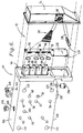
- the electronic control assembly 72 includes a housing 76, a plurality of primary, electronically controlled valves 78, 80, 82, 84, and a plurality of pressure transducers 86, 88, 90, 92.
- the housing 76 attaches to a control face 94 of the manifold 24 with fasteners 96 and includes a manifold cable connector 98.
- a manifold cable 100 plugs into the cable connector 98 and extends to a T-joint 102.
- a CCU cable 104 extends from the T-joint to a CCU 106 which is in communication with control wiring 108 extending between the passenger rail cars.
- a brake cable 110 also extends from the T-joint 102 to the braking device.
- the primary, electronically controlled valves comprise an emergency fill valve 78, a normal braking fill valve 80, a vent valve 82, and a bypass valve 84.
- the primary valves are preferably solenoid valves mounted on the control face 94 of the manifold 24.
- Valve control wires 112 extend from the manifold cable connector 98 and connect to the primary valves. Each valve uses approximately 0.5 Watts for operation.
- An air feed line 114 is in pneumatic communication with one of the control reservoirs 48, 54, preferably the primary control reservoir 48, and each of the primary valve.
- a filter 116 is placed in the primary control reservoir passageway 50 prevent air passages in the primary valves from being dogged.
- the filter 116 is sealed in the manifold by a filter plug 118 on the bottom 120 of the manifold 24.
- the pressure transducers comprise a brake pipe pressure sensor 86, a primary control reservoir pressure sensor 88, an emergency control reservoir pressure sensor 90, and a manifold relay passageway pressure sensor 92.
- the pressure transducers are sealed with O-rings 122 in pneumatic communication with the corresponding passageways.
- the manifold relay passageway pressure sensor 92 is in pneumatic communication with a pipe bracket side manifold relay passageway 124 seen on a pipe bracket side 126 (Fig. 4) of the manifold and pneumatically communicating with the pipe bracket relay passageway 46.
- Pressure sensor control wires 130 extend from the manifold cable connector 98 and connect to a PCB 132 with an electronic connector 134.
- the PCB operatively mounts the pressure sensors 86-92, and the PCB 132 is mounted on the control face 94 with fasteners (not shown).
- the manifold relay passageway also has a service valve side with an electronic control portion 128.
- the manifold also defines an electronic control primary reservoir passageway 129 and an electronic control emergency reservoir passageway 131 extending from the primary control reservoir passageway 50 and the emergency control reservoir passageway 52, respectively.
- the pneumatic control assembly 74 includes a plurality of secondary, pneumatically controlled valves 136, 138, 140, 142 and a pneumatic control portion 143 of the service valve side of the manifold relay passageway.
- the pneumatic control portion 143 is in communication with the service valve relay passageway 70.
- the secondary valves comprise an emergency fill valve 136, a normal braking fill valve 138, a vent valve 140, and a manifold relay valve 142.
- the secondary emergency, fill valve 136 is in pneumatic communication with an emergency valve control line 144 coming from the primary emergency fill valve 78.
- the secondary normal fill valve 138 is in pneumatic communication with a normal fill valve control line 146 coming form the primary normal fill valve 80.
- the secondary vent valve 140 communicates with a vent valve control line 148 extending from the primary vent valve 82, and the manifold relay valve 142 is in pneumatic communication with a bypass control line 150 from the bypass valve 84.
- the electronic control primary reservoir passageway 129 extends from the primary reservoir passageway 50 to the secondary, normal braking fill valve 138, and the electronic control emergency reservoir passageway 131 extends from the emergency reservoir passageway 52 and terminates at the secondary, emergency fill valve 136.
- the pipe bracket side 124 of the manifold relay passageway terminates at the manifold relay valve 142, and the pneumatic control portion 143 of the service valve side of the manifold relay passageway terminates on the opposite side of the pneumatically controlled manifold relay valve 142.
- the electronic control portion 128 of the service valve side of the manifold relay passageway also terminates at the manifold relay valve 142 on the same side as the pneumatic control portion 143.
- the electronic control portion 128 is also in pneumatic communication with the secondary, normal and emergency fill valves 138, 136 opposite the electronic control primary and emergency reservoir passageways 129, 131. Further, the electronic control portion 128 is in pneumatic communication with the secondary vent valve 140, and a vent line 156 extends from the vent valve to a vent 158 in the bottom 120 of the manifold 24.
- the vent is preferably open to atmosphere.
- a volume adding chamber 160 is mounted on the pipe bracket 26 and is in pneumatic communication with the electronic control portion 128 of the valve side of the manifold relay passageway.
- the chamber has a volume of approximately seventeen (17) cubic inches which is optimal for the braking system shown. Other sizes would be optimal for other braking systems.
- a chamber hose 162 is connected to a hose connector 164 which connects to a chamber line 163 at a top 166 of the manifold 24.
- the chamber line 163 extends to the electronic control portion 128 of the manifold relay passageway.
- a test port 168 for testing the operation of the manifold 24, opens on the top 166 of the manifold and connects to the pipe bracket side manifold relay passageway 124.
- a plug 170 covers the test port 168 during normal operation.
- a plurality of bolt holes 172 extend through the comers of the manifold to attach the manifold between the pipe bracket and the service valve.
- a threaded primary reservoir passageway, speed control orifice 174 is positioned on the pipe bracket side 126 of the manifold, and an emergency reservoir passageway, speed control orifice 176 also positioned on the pipe bracket side of the manifold 24. Alternatively, needle valves could be used in place of the orifices 174, 176.
- An alignment pin 178 extends from the pipe bracket side 126 of the manifold 24 to align the manifold with the pipe bracket 26. The alignment pint 178 also prevents the manifold 24 from being installed in an incompatible braking system.
- the bypass valve 84 is energized causing air pressure from the primary control reservoir 48 to pass through the primary control reservoir passageway 50 and into the electronic control primary reservoir passageway 129.
- air passes through the electronic control passageway 129 it also passes through filter 116 which filters the air to prevent the primary valves 78, 80, 82, 84 from clogging with debris.
- the air flows through the air feed line 114 to the bypass valve and from the by pass valve through the bypass control line 150 to the manifold relay valve 142.
- the manifold relay valve 142 pneumatically connects the electronic control portion 128 of the service valve side of the manifold relay passageway to the pipe bracket side manifold relay passageway 124.
- the bypass valve 84 is de-energized cutting off the air supply to the manifold relay valve 142.
- the spring of the manifold relay valve 142 places the pipe bracket side manifold relay passageway 124 into pneumatic communication with the pneumatic control portion 143 of the service valve side of the manifold relay passageway thereby connecting the service valve relay passageway 70 with the pipe bracket side relay passageway 124.
- the manifold 24 becomes essentially invisible to the braking system 22, and the braking system operates as if the manifold were not them.
- the bypass valve 84 and manifold relay valve 142 are operative to connect a selected one of the pneumatic control portion 143 and the electronic control portion 128 with the pipe bracket side manifold relay passageway 124.
- Pneumatic control is used primarily in emergency breaking situations. For example, if the brake pipe 28 ruptures, the emergency vent valve 40 detects a sudden drop in pressure and immediately vents additional pressure from the brake pipe 28 through emergency vent passageway 38. The brake pipe pressure sensor 86 also detects the pressure drop, and the bypass valve 84 is de-energized, so that the service valve 30 responds to the drop in pressure to brake the train. The manifold 24 is biased toward pneumatic control in that when all the primary valves are de-energized, as would occur with a loss of electrical power, the braking system 22 is returned to pneumatic control. Specifically, when the primary emergency fill, fill, and vent valves 78.
- the bypass valve 84 is energized for electronic operation of the braking system 22.
- the signal is transmitted by the control wiring 108 to the CCU 106 of each passenger rail car 20.
- the CCU 106 actuates the primary, normal braking fill valve 80 passing air from the air feed line 114 to the normal fill valve control line 146 which opens the secondary, normal fill valve 138 which is operative to selectively interrupt and permit the flow of pressurized air.
- the secondary fill valve 138 open, air pressure from the primary control reservoir 48 flows from the electronic control, primary reservoir passageway 129 into the electronic control portion 128 of the manifold relay passageway.
- the air pressure then passes through the manifold relay valve 142, into the pipe bracket side manifold relay passageway 124, through the pipe bracket relay passageway 46, and into the brake application relay valve 32.
- the manifold relay passageway pressure sensor 92 monitors the pressure in the relay passageways, and when the pressure is sufficiently high for the amount of braking indicated by the train engineer, the primary fill valve 80 is de-energized to close the secondary fill valve 138.
- the brake application relay valve 32 It connects the main reservoir passageway 42 with the brake line passageway 34, so that pressure from the main reservoir 44 passes to the braking device 36 thereby braking the passenger rail car 20.
- the pressurized air fills the electronic control portion 128 of the manifold relay passageway, it also fills the volume adding chamber 160.
- the chamber 160 operates to slow the pressure increase in the relay passageways giving the sensor 92, CCU 106, and valves 80, 138 time to respond to the pressure rise and close the secondary fill valve 138 at the correct moment Without the chamber 160, the pressure can increase to quickly for the valves to respond causing the system to repeatedly and fill during braking.
- the primary vent valve 82 When the braking is complete, the primary vent valve 82 is then energized transmitting air from the air feed line 114 to the vent valve control line 148 opening the secondary vent valve 140.
- the open secondary vent valve 140 vents the volume adding chamber 160 and the relay passageways 46, 124, 128 through vent line 156 and vent 158 to atmosphere.
- the brake application relay valve 32 severs the pneumatic connection between the main reservoir 44 and the braking device 36 to cease braking the train.
- the primary emergency fill valve 78 is also energized. Once energized, the emergency fill valve 78 transmits pressure from the air feed line 114 to the emergency fill valve control line 144 opening the secondary emergency fill valve 136. When open, the secondary fill valve 136 transmits pressure from the emergency control reservoir 54 through the emergency control reservoir passageways into the electronic control portion 128 of the manifold relay passageway. The increased pressure in the relay passageways causes the brake application relay valve 32 to transmit increased pressure from the main reservoir 44 to the braking device 36.
- the brake pipe sensor 86, primary control reservoir passageway sensor 88, and emergency control reservoir passageway sensor 90 monitor the air pressure in the brake pipe 28, primary control reservoir 48, and emergency control reservoir 54. If a substantial and sudden drop in pressure is detected, caused perhaps by a rupture, the bypass valve is de-energized returning the system to pneumatic control, so that the service valve 30 can enact an emergency brake of the train.
- the primary reservoir passageway, speed control orifice 174 controls the speed at which air flows through the electronic control primary reservoir passageway 129
- the emergency reservoir passageway, speed control orifice 176 controls the speed at which air flows through the electronic control emergency reservoir passageway 131.
- the orifices control the rate of fill in the relay passageways and hence control the braking of the train.
- the orifices are threaded out of the manifold and replaced by larger orifices.
- To decrease the fill rate the orifices are removed and replaced by smaller orifices. The larger the orifice the faster that braking will occur, and the smaller the orifice the slower that braking will occur.
- the manifold 24 has been specially designed to incorporate features, such as the quick service passageways 66, 68 and main reservoir passageways 42, 45, allowing these known features to continue their normal operation even under electronic control of the braking system 22.
- the manifold 24 address the complexity of passenger train braking systems and allows for cost effective retrofitting of passenger train pneumatic braking systems to electronic control.
Landscapes
- Engineering & Computer Science (AREA)
- Transportation (AREA)
- Mechanical Engineering (AREA)
- Valves And Accessory Devices For Braking Systems (AREA)
- Braking Systems And Boosters (AREA)
Applications Claiming Priority (2)
| Application Number | Priority Date | Filing Date | Title |
|---|---|---|---|
| US160606 | 1998-09-25 | ||
| US09/160,606 US6086163A (en) | 1998-09-25 | 1998-09-25 | Electronic interface manifold adapter for railroad passenger cars |
Publications (2)
| Publication Number | Publication Date |
|---|---|
| EP0989040A2 true EP0989040A2 (fr) | 2000-03-29 |
| EP0989040A3 EP0989040A3 (fr) | 2002-05-15 |
Family
ID=22577581
Family Applications (1)
| Application Number | Title | Priority Date | Filing Date |
|---|---|---|---|
| EP99118289A Withdrawn EP0989040A3 (fr) | 1998-09-25 | 1999-09-15 | Adaptateur d'un bloc collecteur d'interface électronique destiné à des wagons pour passagers |
Country Status (7)
| Country | Link |
|---|---|
| US (1) | US6086163A (fr) |
| EP (1) | EP0989040A3 (fr) |
| AR (1) | AR020530A1 (fr) |
| AU (1) | AU4758699A (fr) |
| BR (1) | BR9904308A (fr) |
| CA (1) | CA2280707A1 (fr) |
| ZA (1) | ZA995565B (fr) |
Cited By (7)
| Publication number | Priority date | Publication date | Assignee | Title |
|---|---|---|---|---|
| CN103661427A (zh) * | 2012-09-04 | 2014-03-26 | 中国北车集团大同电力机车有限责任公司 | 辅助供风装置及电力机车 |
| WO2018052436A1 (fr) * | 2016-09-16 | 2018-03-22 | New York Air Brake, LLC | Module de configuration pneumatique pour système de frein pneumatique électronique |
| WO2019015757A1 (fr) * | 2017-07-20 | 2019-01-24 | Knorr-Bremse Systeme für Schienenfahrzeuge GmbH | Unité de commande de frein à encombrement réduit |
| EP3623239A1 (fr) * | 2018-09-11 | 2020-03-18 | KNORR-BREMSE Systeme für Schienenfahrzeuge GmbH | Module de configuration |
| US20210284117A1 (en) * | 2020-03-10 | 2021-09-16 | Carlisle Industrial Brake & Friction | Modular Electronic Brake System |
| EP4052976A1 (fr) * | 2021-03-05 | 2022-09-07 | KNORR-BREMSE Systeme für Schienenfahrzeuge GmbH | Carter pour soupape de commande et soupape de commande |
| EP4177480A4 (fr) * | 2021-09-24 | 2023-08-09 | Meishan CRRC Brake Science & Technology Co., Ltd. | Dispositif de conversion, système de freinage et train |
Families Citing this family (15)
| Publication number | Priority date | Publication date | Assignee | Title |
|---|---|---|---|---|
| US6883874B2 (en) * | 2000-09-14 | 2005-04-26 | New York Air Brake Corporation | Pressure sensor module |
| US6472769B1 (en) * | 2000-09-14 | 2002-10-29 | New York Air Brake Corporation | Car control device assembly |
| US20050276153A1 (en) * | 2004-06-14 | 2005-12-15 | Systech, Inc. | Integrated control system |
| WO2006122374A1 (fr) * | 2005-05-20 | 2006-11-23 | Queensland Rail | Systeme de freinage pneumatique a pilotage electronique |
| CN101376391B (zh) * | 2007-08-30 | 2012-05-30 | 南车青岛四方机车车辆股份有限公司 | 轨道车辆制动系统集成装置及其集成方法 |
| DE102008009217A1 (de) * | 2008-02-12 | 2009-08-20 | Siemens Aktiengesellschaft | Modulares Bremsgerüst |
| DE102008048562A1 (de) * | 2008-09-23 | 2010-04-29 | Knorr-Bremse Systeme für Schienenfahrzeuge GmbH | Ventilanordnung zur Brems- sowie Zusatzgeräteansteuerung einer pneumatischen Bremsanlage eines Fahrzeuges |
| DE102016000760A1 (de) * | 2016-01-27 | 2017-07-27 | Siemens Aktiengesellschaft | Schaltung und Verteilerblock und aus diesen gebildete Bremssteueranordnung für Schienenfahrzeuge sowie Verteilersatz zum Konfigurieren und Verfahren zur Bildung der Bremssteueranordnung |
| US10214195B1 (en) | 2017-08-30 | 2019-02-26 | Westinghouse Air Brake Technologies Corporation | Automatic brake control valve test unit for railway vehicle |
| US10543827B2 (en) | 2017-08-30 | 2020-01-28 | Westinghouse Air Brake Technologies Corporation | System for accessing integral pressures of brake control valve |
| US11027756B2 (en) | 2017-11-16 | 2021-06-08 | Westinghouse Air Brake Technologies Corporation | ECP overlay system for UIC-type distributor valve |
| US10994756B2 (en) | 2017-11-16 | 2021-05-04 | Westinghouse Air Brake Technologies Corporation | Electronically controlled brake overlay system for distributor valve |
| US11014585B2 (en) | 2017-11-16 | 2021-05-25 | Westinghouse Air Brake Technologies Corporation | ECP overlay system for W-type triple valve |
| CN110539774B (zh) * | 2018-06-25 | 2021-05-18 | 中车长春轨道客车股份有限公司 | 一种bp救援系统及轨道列车 |
| ES3037066T3 (en) * | 2021-03-05 | 2025-09-26 | Knorr Bremse Systeme | Interface adapter for a control valve and control valve with an interface adapter |
Citations (3)
| Publication number | Priority date | Publication date | Assignee | Title |
|---|---|---|---|---|
| US5335974A (en) | 1993-03-19 | 1994-08-09 | Technical Services & Marketing, Inc. | Retrofit of railcar air brake system with electronic controller and air distribution apparatus |
| US5735580A (en) | 1995-11-20 | 1998-04-07 | Technical Services And Marketing Inc. | Rail car load sensor |
| US5813730A (en) | 1996-11-26 | 1998-09-29 | Technical Services And Marketing, Inc. | Retrofit air distribution apparatus for a locomotive braking system |
Family Cites Families (11)
| Publication number | Priority date | Publication date | Assignee | Title |
|---|---|---|---|---|
| US3709564A (en) * | 1971-07-22 | 1973-01-09 | Westinghouse Air Brake Co | Combined electronic and fluid pressure brake apparatus |
| US4509801A (en) * | 1983-11-18 | 1985-04-09 | General Signal Corporation | Fluid pressure brake control systems for freight locomotives |
| US4586584A (en) * | 1985-04-08 | 1986-05-06 | General Motors Corporation | Truck brake control system |
| US5249125A (en) * | 1989-12-08 | 1993-09-28 | Knorr Brake Holding Corporation | Computer controlled railway brake equipment |
| US5572187A (en) * | 1994-05-23 | 1996-11-05 | Williford; Robert F. | Air brake monitoring and safety system |
| US5738416A (en) * | 1994-07-22 | 1998-04-14 | Westinghouse Air Brake Company | Railway braking apparatus to effect a change in a handbrake |
| US5676431A (en) * | 1995-09-06 | 1997-10-14 | New York Air Brake Corporation | Electropneumatic pilot adapter |
| US5924774A (en) * | 1995-11-30 | 1999-07-20 | Zeftron, Inc. | Electronic pneumatic brake system |
| US5967620A (en) * | 1996-09-06 | 1999-10-19 | New York Air Brake Corporation | Electropneumatic brake control valve |
| US5988766A (en) * | 1997-07-03 | 1999-11-23 | New York Air Brake Corporation | Electropneumatical brake adaptor |
| BR9907961B1 (pt) * | 1998-02-17 | 2011-05-31 | sistema de freio para um trem. |
-
1998
- 1998-09-25 US US09/160,606 patent/US6086163A/en not_active Expired - Lifetime
-
1999
- 1999-08-23 CA CA002280707A patent/CA2280707A1/fr not_active Abandoned
- 1999-08-30 ZA ZA9905565A patent/ZA995565B/xx unknown
- 1999-09-14 AU AU47586/99A patent/AU4758699A/en not_active Abandoned
- 1999-09-15 EP EP99118289A patent/EP0989040A3/fr not_active Withdrawn
- 1999-09-22 BR BR9904308-4A patent/BR9904308A/pt not_active Application Discontinuation
- 1999-09-24 AR ARP990104851A patent/AR020530A1/es active IP Right Grant
Patent Citations (3)
| Publication number | Priority date | Publication date | Assignee | Title |
|---|---|---|---|---|
| US5335974A (en) | 1993-03-19 | 1994-08-09 | Technical Services & Marketing, Inc. | Retrofit of railcar air brake system with electronic controller and air distribution apparatus |
| US5735580A (en) | 1995-11-20 | 1998-04-07 | Technical Services And Marketing Inc. | Rail car load sensor |
| US5813730A (en) | 1996-11-26 | 1998-09-29 | Technical Services And Marketing, Inc. | Retrofit air distribution apparatus for a locomotive braking system |
Cited By (15)
| Publication number | Priority date | Publication date | Assignee | Title |
|---|---|---|---|---|
| CN103661427A (zh) * | 2012-09-04 | 2014-03-26 | 中国北车集团大同电力机车有限责任公司 | 辅助供风装置及电力机车 |
| CN103661427B (zh) * | 2012-09-04 | 2016-03-23 | 中国北车集团大同电力机车有限责任公司 | 辅助供风装置及电力机车 |
| WO2018052436A1 (fr) * | 2016-09-16 | 2018-03-22 | New York Air Brake, LLC | Module de configuration pneumatique pour système de frein pneumatique électronique |
| CN109715457A (zh) * | 2016-09-16 | 2019-05-03 | 纽约气闸有限公司 | 用于电子空气制动系统的气动配置模块 |
| US10807575B2 (en) | 2016-09-16 | 2020-10-20 | New York Air Brake, LLC | Pneumatic configuration module for electronic air brake system |
| WO2019015757A1 (fr) * | 2017-07-20 | 2019-01-24 | Knorr-Bremse Systeme für Schienenfahrzeuge GmbH | Unité de commande de frein à encombrement réduit |
| WO2020053284A1 (fr) * | 2018-09-11 | 2020-03-19 | Knorr-Bremse Systeme für Schienenfahrzeuge GmbH | Module de configuration |
| EP3623239A1 (fr) * | 2018-09-11 | 2020-03-18 | KNORR-BREMSE Systeme für Schienenfahrzeuge GmbH | Module de configuration |
| US11702055B2 (en) | 2018-09-11 | 2023-07-18 | Knorr-Bremse Systeme für Schienenfahrzeuge GmbH | Configuration module |
| US20210284117A1 (en) * | 2020-03-10 | 2021-09-16 | Carlisle Industrial Brake & Friction | Modular Electronic Brake System |
| US11685354B2 (en) * | 2020-03-10 | 2023-06-27 | Carlisle Industrial Brake & Friction | Modular electronic brake system |
| EP4052976A1 (fr) * | 2021-03-05 | 2022-09-07 | KNORR-BREMSE Systeme für Schienenfahrzeuge GmbH | Carter pour soupape de commande et soupape de commande |
| WO2022184448A1 (fr) * | 2021-03-05 | 2022-09-09 | Knorr-Bremse Systeme für Schienenfahrzeuge GmbH | Boîtier de soupape pour une soupape de commande et soupape de commande |
| CN116917176A (zh) * | 2021-03-05 | 2023-10-20 | 克诺尔轨道车辆系统有限公司 | 用于控制阀的阀壳体和控制阀 |
| EP4177480A4 (fr) * | 2021-09-24 | 2023-08-09 | Meishan CRRC Brake Science & Technology Co., Ltd. | Dispositif de conversion, système de freinage et train |
Also Published As
| Publication number | Publication date |
|---|---|
| AR020530A1 (es) | 2002-05-15 |
| CA2280707A1 (fr) | 2000-03-25 |
| AU4758699A (en) | 2000-03-30 |
| BR9904308A (pt) | 2001-03-20 |
| ZA995565B (en) | 2000-03-27 |
| US6086163A (en) | 2000-07-11 |
| EP0989040A3 (fr) | 2002-05-15 |
Similar Documents
| Publication | Publication Date | Title |
|---|---|---|
| US6086163A (en) | Electronic interface manifold adapter for railroad passenger cars | |
| CA2320071C (fr) | Systeme de freinage de vehicules sur rails | |
| US5934764A (en) | Method for limiting brake cylinder pressure on locomotives equipped with distributive power and electronic brake systems | |
| US6189980B1 (en) | Locomotive to ECP brake conversion system | |
| EP1270353B1 (fr) | Système de valve de commande à charge variable et à quatre voies pour un système de freinage avec conduite de freinage | |
| US5335974A (en) | Retrofit of railcar air brake system with electronic controller and air distribution apparatus | |
| CA2174910C (fr) | Appareil de commande de charge pour systeme de freinage electropneumatique a microprocesseur | |
| JPH0667724B2 (ja) | 流体圧力ブレ−キ装置 | |
| US4641892A (en) | Railway emergency brake system | |
| CA2147096C (fr) | Dispositif pour le controle des freins d'une locomotive | |
| US7144090B2 (en) | China type 120 brake valve ECP manifold | |
| AU742660B2 (en) | Application solenoid valve for electronically controlled freight train brake system | |
| US5813730A (en) | Retrofit air distribution apparatus for a locomotive braking system | |
| CA1265562A (fr) | Systeme de commande-regulation du freinage sur locomotive | |
| US2379308A (en) | Fluid pressure brake apparatus | |
| CA2568461C (fr) | Systeme de commande de conduite du frein avec wagon a radiocommande | |
| MXPA99008808A (es) | Adaptador de multiple de interfaz electronica para vagones ferroviarios de pasajeros | |
| CA2202938C (fr) | Systeme de freinage de penalite pour equipement de commande de conduite du frein direct | |
| EP0982209B1 (fr) | Dispositif de freinage, en particulier pour des trains de grande longueur | |
| CA2203047C (fr) | Circuit de freinage de penalite pour equipement de commande de conduite du frein direct | |
| CA2203048C (fr) | Modele de freinage de penalite pour equipement de commande de conduite du frein direct | |
| HK1026877A (en) | Application solenoid valve for electronically controlled freight train brake system | |
| MXPA99006357A (en) | Solenoid valve of application for electronically control loading brake system | |
| HK1031350A (en) | Locomotive to ecp brake conversion system |
Legal Events
| Date | Code | Title | Description |
|---|---|---|---|
| PUAI | Public reference made under article 153(3) epc to a published international application that has entered the european phase |
Free format text: ORIGINAL CODE: 0009012 |
|
| AK | Designated contracting states |
Kind code of ref document: A2 Designated state(s): AT BE CH CY DE DK ES FI FR GB GR IE IT LI LU MC NL PT SE |
|
| AX | Request for extension of the european patent |
Free format text: AL;LT;LV;MK;RO;SI |
|
| RIN1 | Information on inventor provided before grant (corrected) |
Inventor name: HRENCHIR, ROBERT D. Inventor name: KLINK, DOUGLAS D. |
|
| PUAL | Search report despatched |
Free format text: ORIGINAL CODE: 0009013 |
|
| AK | Designated contracting states |
Kind code of ref document: A3 Designated state(s): AT BE CH CY DE DK ES FI FR GB GR IE IT LI LU MC NL PT SE |
|
| AX | Request for extension of the european patent |
Free format text: AL;LT;LV;MK;RO;SI |
|
| 17P | Request for examination filed |
Effective date: 20020907 |
|
| AKX | Designation fees paid |
Designated state(s): DE FR GB IT |
|
| STAA | Information on the status of an ep patent application or granted ep patent |
Free format text: STATUS: THE APPLICATION IS DEEMED TO BE WITHDRAWN |
|
| 18D | Application deemed to be withdrawn |
Effective date: 20030401 |