EP0989053A2 - Construction de plancher d'une cabine d'un camion - Google Patents
Construction de plancher d'une cabine d'un camion Download PDFInfo
- Publication number
- EP0989053A2 EP0989053A2 EP99114918A EP99114918A EP0989053A2 EP 0989053 A2 EP0989053 A2 EP 0989053A2 EP 99114918 A EP99114918 A EP 99114918A EP 99114918 A EP99114918 A EP 99114918A EP 0989053 A2 EP0989053 A2 EP 0989053A2
- Authority
- EP
- European Patent Office
- Prior art keywords
- engine tunnel
- additional
- longitudinal
- cross
- hat
- Prior art date
- Legal status (The legal status is an assumption and is not a legal conclusion. Google has not performed a legal analysis and makes no representation as to the accuracy of the status listed.)
- Granted
Links
Images


Classifications
-
- B—PERFORMING OPERATIONS; TRANSPORTING
- B62—LAND VEHICLES FOR TRAVELLING OTHERWISE THAN ON RAILS
- B62D—MOTOR VEHICLES; TRAILERS
- B62D21/00—Understructures, i.e. chassis frame on which a vehicle body may be mounted
- B62D21/15—Understructures, i.e. chassis frame on which a vehicle body may be mounted having impact absorbing means, e.g. a frame designed to permanently or temporarily change shape or dimension upon impact with another body
-
- B—PERFORMING OPERATIONS; TRANSPORTING
- B62—LAND VEHICLES FOR TRAVELLING OTHERWISE THAN ON RAILS
- B62D—MOTOR VEHICLES; TRAILERS
- B62D25/00—Superstructure or monocoque structure sub-units; Parts or details thereof not otherwise provided for
- B62D25/20—Floors or bottom sub-units
-
- B—PERFORMING OPERATIONS; TRANSPORTING
- B62—LAND VEHICLES FOR TRAVELLING OTHERWISE THAN ON RAILS
- B62D—MOTOR VEHICLES; TRAILERS
- B62D33/00—Superstructures for load-carrying vehicles
- B62D33/06—Drivers' cabs
Definitions
- the invention relates to a floor construction according to the preambles of claims 1 to 3 a truck cab, with essentially an approximately hat-shaped shaped engine tunnel sheet, possibly several floor sheets and inner and outer longitudinal or cross members.
- the load-bearing structure of the floor assembly is usually used thanks to an engine tunnel plate designed for the respective engine installation as well as floor plates and side members connected to it.
- an engine tunnel plate designed for the respective engine installation as well as floor plates and side members connected to it.
- a floor structure of a truck cab to create an adequate in the event of a crash of the truck Ensures survival space for the occupants in the cab.
- a floor structure which is characterized in that in an upper and / or a lower area of the hat profile of the engine tunnel sheet formed, spaced upper and / or lower longitudinal edges for the longitudinal reinforcement of the engine tunnel sheet, each of additional, in cross section approximately hat-shaped profiled upper and / or lower side members covered and connected to these, with the engine tunnel plate in the area its upper and / or lower longitudinal edges each along the same together with the additional upper and / or lower side members in cross-section approximately Forms of closed box girders.
- this object is according to the features of Claim 2 solved by a floor structure, which is characterized in that that an upper horizontal section formed in an upper region of the engine tunnel sheet for the purpose of longitudinal reinforcement of the engine tunnel sheet in areas of an additional, longitudinally profiled longitudinal member covered in cross-section and is connected thereto, the upper horizontal portion of the engine tunnel plate along the same cross-section together with the additional side member forms the shape of a closed box girder.
- the task is according to the invention by a floor construction solved, which is characterized according to claim 3, characterized in that in an upper and / or the lower region of the hat profile of the engine tunnel sheet, to one another spaced upper and / or lower longitudinal edges for longitudinal reinforcement of the engine tunnel sheet each of additional, in cross section approximately hat-shaped profiled upper and / or lower side members covered and with these are connected, the engine tunnel sheet in the area of its upper and / or lower longitudinal edges each along the same along with the additional upper and / or lower longitudinal beams in cross-section approximately the shape of closed Box girder forms, and that one in an upper area of the engine tunnel sheet formed upper horizontal section for the purpose of longitudinal reinforcement of the engine tunnel sheet in areas of an additional, approximately hat-shaped in cross section profiled, upper side member covered and connected to it, the upper horizontal section of the engine tunnel plate along with it the additional side member is approximately closed in cross section Box girder forms.
- Solutions is a favorable power distribution between the lower ones or upper side members and the respective upper or lower longitudinal edges of the Engine tunnel sheet metal as well as the front wall and the seat cross member. So can on the one hand, when the driver's cab is subjected to a high level of force, the loads are almost directly Line be directed from front to back. On the other hand, deeper ones Force attacks on the cab, e.g. B. at the level of a front cab storage area carry the engine tunnel sheet in such a way that all of them buckle Longitudinal beam of the floor construction is omitted.
- the reinforcement of the longitudinal edges and possibly the upper horizontal section of the engine tunnel sheet by means of additional upper and / or lower side members taken into account in their design the available space in the upper or lower area of the hat profile of the engine tunnel sheet and its contour is adapted.
- the additional top or lower side members are in particular the dimensions of the floor structure adapted to the dimensions of the engine tunnel sheet.
- the additional Upper and lower side members can be attached by means of protruding mounting flanges by spot welding, seam welding, screwing, riveting and / or structural gluing on the engine tunnel sheet and possibly on the front wall, Seat cross member or other cross members of the floor structure attached his.
- the material properties of the upper and lower side members can differ in Dependence on their loads and their geometry from those of the engine tunnel sheet differentiate.
- All of the additional side members can either as one-piece components or as separate, sectionally formed in their longitudinal direction, Multi-part components can be executed, the latter by in the transverse direction running welds, bonds, rivets or screw connections with each other can be connectable.
- the protruding from the additional side members Mounting flanges can either be continuous or in sections be trained. Furthermore, can be covered by the additional side members Cavities for the purpose of noise insulation using a plastic foam be foamed.
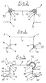
- Fig. 1 is seen in perspective exploded view obliquely from behind a floor construction of a truck cab with essentially one hat-shaped engine tunnel sheet 1 and the same on both sides connected to it
- Floor plates 6, 7 shown that also belong to the floor construction inner and outer side members are not for reasons of clarity shown.
- the engine tunnel sheet 1, the floor sheets 6, 7 and those not shown here Side members are each formed by pressed metal parts.
- the engine tunnel sheet 1 has in an upper region two upper ones running approximately parallel to one another Longitudinal edges 2, 3 on the inside of the cab for the purpose of longitudinal reinforcement of the engine tunnel sheet 1 each with an additional, approximately hat-shaped profiled upper Longitudinal beams 8, 9 covered and with this by means of a known type of connection, for example a spot weld, a seam weld, a screw connection, riveting and / or structural bonding.
- a known type of connection for example a spot weld, a seam weld, a screw connection, riveting and / or structural bonding.
- Engine tunnel plate 1 fastened on the front to an end wall 32 and has in one rear area a cross beam only indicated here in dash-dotted lines Seat attachment 33 on.
- the two upper side members 8, 9 extend lengthways of the engine tunnel sheet 1 between the end wall 32 and the seat fastening 33 and attachable to this via transverse flanges, not shown here.
- FIG. 2 in a sectional view, on the additional upper Side rails 8, 9 provided on the outside, integrally formed with these mounting flanges 10, 12; 11, 13 are for their connection to the engine tunnel plate 1 either completely continuous or only in sections.
- the one from the Upper side members 8, 9 covered cavities can be covered with a plastic foam 73 be foamed.
- FIG. 3 shows a further variant of a reinforcement of an engine tunnel sheet 1.
- this version are in a lower area of the hat profile of the engine tunnel sheet 1 inside the cab, two lower ones running approximately parallel to each other Longitudinal edges 4, 5 for the purpose of longitudinal reinforcement of the engine tunnel sheet 1 of additional, about hat-shaped profiled lower side members 14, 15 and with these using a type of connection, such as spot welding, seam welding, screwing, riveting and / or structural gluing connected.
- a type of connection such as spot welding, seam welding, screwing, riveting and / or structural gluing connected.
- the engine tunnel sheet 1 reinforcing lower side members 14, 15 have either completely continuous outside or fastening flanges 16, 18 running in sections; 17, 19 for a connection to the lower area of the hat profile of the engine tunnel sheet 1 on.
- Fig. 4 is a third variant of a floor construction schematically with solid lines of a truck cab shown in cross section.
- Motor tunnel sheet 1 both in the area of its upper longitudinal edges 2, 3 and in Area of its lower longitudinal edges 4, 5 of additional upper and lower Side members 8, 9; 14, 15 each reinforced inside the cab.
- a fourth variant of a floor construction is shown in dashed lines.
- the additional upper and lower side members 8, 9; 14, 15 of others upper and lower side members 20, 21; 26, 27 covered and with these over fastening flanges running continuously or partially along their circumference 22, 24; 23, 25; 28, 30; 29, 31 connected.
- the additional top and bottom Side members 20, 21; 26, 27 can by spot welding, seam welding, a screw connection, riveting and / or structural gluing be fixed to their respective location.
- the additional top and bottom Side members 20, 21; 26, 27 can over transverse flanges, not shown here additionally on the end wall 32 and / or on a cross member of the seat fastening 33 and / or on the transverse flanges 42, 43 (FIG. 7) of the one below located longitudinal beams 8, 9; 14, 15 can be fastened.
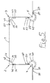
- FIG. 5 is a fifth variant of a schematic with solid lines Floor construction of a truck cab shown in cross section.
- Motor tunnel sheet 1 both in the area of its upper longitudinal edges 2, 3 and in Area of its lower longitudinal edges 4, 5 of additional upper and lower Side members 34, 35; 36, 37 each reinforced on the motor side.
- Their mounting flanges 46, 48; 47, 49; 50, 52; 51, 53 are each resting on the engine tunnel sheet 1 connected to this via one of the aforementioned types of connection.
- a sixth variant of a floor construction is in dashed lines of a truck cab shown in cross section.
- Fig. 4 the additional upper and lower side members 34, 35; 36, 37 of further upper or lower longitudinal beams 38, 39; 40, 41 covered and with these and / or with the engine tunnel sheet 1 over its circumference continuously or partially extending mounting flanges 54, 56; 55, 57; 58, 60; 59, 61 over one of the aforementioned connection types connected.
- all side members can be combined in any combination Arrangement options, both inside the cab and on the engine side be attachable to the engine tunnel sheet 1.
- FIGS. 4 and 5 are schematically and in cross section, among each other and optionally additionally with the possible design variants described in FIGS. 4 and 5 Combinable design versions of a floor construction of a truck cab. So is a solid line in one upper area of the engine tunnel sheet 1 formed upper horizontal section 45 On the inside of the driver's cab for the purpose of longitudinal reinforcement of the engine tunnel sheet 1 of an additional, roughly hat-shaped in cross-section Sidelong 44 covered and with this over protruding mounting flanges 62, 63 connected.
- the upper horizontal section 45 of the engine tunnel sheet forms 1 along the same together with the additional longitudinal member 44 approximately in cross-section the shape of a closed box girder.
- the longitudinal beams 44, 46, 66, 67 can with the rest Longitudinal beams according to FIG. 4 and FIG. 5 can be combined if necessary. Possibly can the additional side members 44, 46, 66, 67 with among other things lower side members 14, 15 can be combined.
- the additional upper and / or lower Side members 8, 9; 14, 15; 20, 21; 26, 27 at least in regions between one front end wall 32 and a seat attachment, for example a seat cross member 33 of the cab extend.
- the upper side member 8 shown here is additional for its aforementioned attachment to the engine tunnel sheet 1 by means of longitudinal mounting flanges 10, 12 (Fig. 2) further on the front end wall 32 via an additional, transverse flange 43 and on the seat cross member 33 via an additional, transverse Flange 42 attached.
- the longitudinal beam 8 is in the embodiment shown here by divided in the longitudinal direction, by extending in the transverse direction Welds 72 formed separate sections 8/1, 8/2, 8/3 interconnected.
- the number of sections can vary as required. Instead of Weld seams can also be glued, screwed or riveted to step.
- the separate sections 8/1, 8/2, 8/3 of the side member 8 can be here partially reach under or overlap each other and / or if necessary Have holes for receiving the screw or rivet connections.
Landscapes
- Engineering & Computer Science (AREA)
- Chemical & Material Sciences (AREA)
- Combustion & Propulsion (AREA)
- Transportation (AREA)
- Mechanical Engineering (AREA)
- Body Structure For Vehicles (AREA)
Applications Claiming Priority (2)
| Application Number | Priority Date | Filing Date | Title |
|---|---|---|---|
| DE1998138941 DE19838941A1 (de) | 1998-08-27 | 1998-08-27 | Bodenkonstruktion eines Lkw-Fahrerhauses |
| DE19838941 | 1998-08-27 |
Publications (3)
| Publication Number | Publication Date |
|---|---|
| EP0989053A2 true EP0989053A2 (fr) | 2000-03-29 |
| EP0989053A3 EP0989053A3 (fr) | 2002-12-18 |
| EP0989053B1 EP0989053B1 (fr) | 2006-05-03 |
Family
ID=7878877
Family Applications (1)
| Application Number | Title | Priority Date | Filing Date |
|---|---|---|---|
| EP19990114918 Expired - Lifetime EP0989053B1 (fr) | 1998-08-27 | 1999-07-30 | Construction de plancher d'une cabine d'un camion |
Country Status (2)
| Country | Link |
|---|---|
| EP (1) | EP0989053B1 (fr) |
| DE (2) | DE19838941A1 (fr) |
Cited By (1)
| Publication number | Priority date | Publication date | Assignee | Title |
|---|---|---|---|---|
| WO2005066014A1 (fr) * | 2003-12-23 | 2005-07-21 | Daimlerchrysler Ag | Gamme de cabines de conducteur conçues de façon modulaire |
Families Citing this family (3)
| Publication number | Priority date | Publication date | Assignee | Title |
|---|---|---|---|---|
| DE102005024265B4 (de) | 2005-05-27 | 2020-08-06 | Audi Ag | Karosserieboden für Kraftfahrzeuge |
| DE102012102447B4 (de) * | 2012-03-22 | 2023-03-02 | Dr. Ing. H.C. F. Porsche Aktiengesellschaft | Tunnelverstärkung und Tragstruktur |
| DE102022100459A1 (de) * | 2022-01-11 | 2023-07-13 | Man Truck & Bus Se | Fahrerhaus für Lastkraftwagen |
Family Cites Families (8)
| Publication number | Priority date | Publication date | Assignee | Title |
|---|---|---|---|---|
| JPS5135849Y2 (fr) * | 1973-05-16 | 1976-09-03 | ||
| DE2408548C2 (de) * | 1974-02-22 | 1982-05-19 | Audi Nsu Auto Union Ag, 7107 Neckarsulm | Wagenkastenunterrahmen für Kraftfahrzeuge |
| DE2435545C3 (de) * | 1974-07-24 | 1979-09-20 | Daimler-Benz Ag, 7000 Stuttgart | Tunnelrandversteifung für einen Triebwerkteile aufnehmenden, in der Bodenmitte eines Personenkraftwagens angeordneten, in Fahrzeuglängsrichtung verlaufenden Tunnel |
| DE3722490A1 (de) * | 1987-07-04 | 1989-02-02 | Treser Automobilbau Gmbh Walte | Bodenplatte fuer ein kraftfahrzeug |
| US5611593A (en) * | 1994-03-16 | 1997-03-18 | Honda Giken Kogyo Kabushiki Kaisha | Automotive floor panel assembly |
| JP3137881B2 (ja) * | 1995-09-01 | 2001-02-26 | 本田技研工業株式会社 | 自動車の車体構造 |
| DE19543404B4 (de) * | 1995-11-21 | 2004-03-11 | Bayerische Motoren Werke Ag | Mitteltunnel für die Bodengruppe eines Kraftfahrzeuges |
| JPH11301530A (ja) * | 1998-04-15 | 1999-11-02 | Isuzu Motors Ltd | 車両のキャブ補強構造 |
-
1998
- 1998-08-27 DE DE1998138941 patent/DE19838941A1/de not_active Withdrawn
-
1999
- 1999-07-30 DE DE59913381T patent/DE59913381D1/de not_active Expired - Lifetime
- 1999-07-30 EP EP19990114918 patent/EP0989053B1/fr not_active Expired - Lifetime
Cited By (1)
| Publication number | Priority date | Publication date | Assignee | Title |
|---|---|---|---|---|
| WO2005066014A1 (fr) * | 2003-12-23 | 2005-07-21 | Daimlerchrysler Ag | Gamme de cabines de conducteur conçues de façon modulaire |
Also Published As
| Publication number | Publication date |
|---|---|
| DE59913381D1 (de) | 2006-06-08 |
| EP0989053A3 (fr) | 2002-12-18 |
| DE19838941A1 (de) | 2000-03-02 |
| EP0989053B1 (fr) | 2006-05-03 |
Similar Documents
| Publication | Publication Date | Title |
|---|---|---|
| EP1525132B1 (fr) | Ensemble de support de sol pour automobile | |
| EP1534578B1 (fr) | Carrosserie a structure portante composee de modules assembles | |
| EP1532040B1 (fr) | Carrosserie de voiture a structure portante composee de modules de grandes dimensions | |
| DE102007006722C5 (de) | Träger für eine Karosserie eines Kraftwagens | |
| EP2547574B1 (fr) | Élément avant d'un véhicule | |
| DE102011121908A1 (de) | Kraftfahrzeugkarosserie mit Verstärkungsstruktur | |
| DE10232840A1 (de) | Bodenstruktur an Kraftfahrzeugen | |
| DE10220025A1 (de) | Querträger | |
| DE10239990A1 (de) | Kraftwagen-Karosserie mit einer Tragstruktur aus großformatigen Teilmodulen | |
| DE102010051256A1 (de) | Kraftfahrzeugkarosserie mit Verstärkungsstruktur | |
| WO2018007204A1 (fr) | Véhicule automobile | |
| DE102010051783A1 (de) | Karosserie für einen Kraftwagen | |
| EP1525133B1 (fr) | Structure de renfort de sol pour automobile | |
| DE1298007B (de) | Unterbau fuer Wagenkasten von Kraftfahrzeugen | |
| EP1534577A1 (fr) | Carrosserie de voiture avec montant | |
| DE19953808B4 (de) | Vorbautragstruktur für eine selbsttragende Karosserie eines Kraftfahrzeugs | |
| DE10032663B4 (de) | Kraftwagen mit einer selbsttragenden Karosserie | |
| DE10018898B4 (de) | Kraftwagen mit einer Tragstruktur | |
| EP0989053A2 (fr) | Construction de plancher d'une cabine d'un camion | |
| DE102020205713A1 (de) | Karosseriestruktur für ein Fahrzeug | |
| DE102005045295B4 (de) | Fahrschemel für ein Kraftfahrzeug | |
| EP1717130A1 (fr) | Structure d'un support de tableau de bord | |
| DE102006055560A1 (de) | Karosseriebauteil für einen Kraftwagen | |
| DE102010054688A1 (de) | Bodenstruktur für ein Kraftfahrzeug, Fahrzeugkarosserie und Kraftfahrzeug | |
| DE10110163B4 (de) | Bodenstruktur im Hinterwagenbereich eines Kraftfahrzeugs |
Legal Events
| Date | Code | Title | Description |
|---|---|---|---|
| PUAI | Public reference made under article 153(3) epc to a published international application that has entered the european phase |
Free format text: ORIGINAL CODE: 0009012 |
|
| AK | Designated contracting states |
Kind code of ref document: A2 Designated state(s): AT BE CH CY DE DK ES FI FR GB GR IE IT LI LU MC NL PT SE |
|
| AX | Request for extension of the european patent |
Free format text: AL;LT;LV;MK;RO;SI |
|
| PUAL | Search report despatched |
Free format text: ORIGINAL CODE: 0009013 |
|
| AK | Designated contracting states |
Kind code of ref document: A3 Designated state(s): AT BE CH CY DE DK ES FI FR GB GR IE IT LI LU MC NL PT SE |
|
| AX | Request for extension of the european patent |
Free format text: AL;LT;LV;MK;RO;SI |
|
| 17P | Request for examination filed |
Effective date: 20030122 |
|
| 17Q | First examination report despatched |
Effective date: 20030414 |
|
| AKX | Designation fees paid |
Designated state(s): DE FR IT NL SE |
|
| GRAP | Despatch of communication of intention to grant a patent |
Free format text: ORIGINAL CODE: EPIDOSNIGR1 |
|
| GRAS | Grant fee paid |
Free format text: ORIGINAL CODE: EPIDOSNIGR3 |
|
| GRAA | (expected) grant |
Free format text: ORIGINAL CODE: 0009210 |
|
| AK | Designated contracting states |
Kind code of ref document: B1 Designated state(s): DE FR IT NL SE |
|
| REF | Corresponds to: |
Ref document number: 59913381 Country of ref document: DE Date of ref document: 20060608 Kind code of ref document: P |
|
| REG | Reference to a national code |
Ref country code: SE Ref legal event code: TRGR |
|
| ET | Fr: translation filed | ||
| PLBE | No opposition filed within time limit |
Free format text: ORIGINAL CODE: 0009261 |
|
| STAA | Information on the status of an ep patent application or granted ep patent |
Free format text: STATUS: NO OPPOSITION FILED WITHIN TIME LIMIT |
|
| 26N | No opposition filed |
Effective date: 20070206 |
|
| REG | Reference to a national code |
Ref country code: NL Ref legal event code: TD Effective date: 20110420 |
|
| REG | Reference to a national code |
Ref country code: FR Ref legal event code: PLFP Year of fee payment: 18 |
|
| REG | Reference to a national code |
Ref country code: FR Ref legal event code: PLFP Year of fee payment: 19 |
|
| REG | Reference to a national code |
Ref country code: FR Ref legal event code: PLFP Year of fee payment: 20 |
|
| PGFP | Annual fee paid to national office [announced via postgrant information from national office to epo] |
Ref country code: FR Payment date: 20180726 Year of fee payment: 20 Ref country code: IT Payment date: 20180725 Year of fee payment: 20 Ref country code: NL Payment date: 20180724 Year of fee payment: 20 |
|
| PGFP | Annual fee paid to national office [announced via postgrant information from national office to epo] |
Ref country code: SE Payment date: 20180731 Year of fee payment: 20 |
|
| PGFP | Annual fee paid to national office [announced via postgrant information from national office to epo] |
Ref country code: DE Payment date: 20180928 Year of fee payment: 20 |
|
| REG | Reference to a national code |
Ref country code: DE Ref legal event code: R071 Ref document number: 59913381 Country of ref document: DE |
|
| REG | Reference to a national code |
Ref country code: NL Ref legal event code: MK Effective date: 20190729 |