EP0989057A2 - Dispositif pour changer la forme de l'aile d'un aéronef - Google Patents
Dispositif pour changer la forme de l'aile d'un aéronef Download PDFInfo
- Publication number
- EP0989057A2 EP0989057A2 EP99117380A EP99117380A EP0989057A2 EP 0989057 A2 EP0989057 A2 EP 0989057A2 EP 99117380 A EP99117380 A EP 99117380A EP 99117380 A EP99117380 A EP 99117380A EP 0989057 A2 EP0989057 A2 EP 0989057A2
- Authority
- EP
- European Patent Office
- Prior art keywords
- wing
- cable
- planking
- actuator
- pull
- Prior art date
- Legal status (The legal status is an assumption and is not a legal conclusion. Google has not performed a legal analysis and makes no representation as to the accuracy of the status listed.)
- Withdrawn
Links
Images

Classifications
-
- B—PERFORMING OPERATIONS; TRANSPORTING
- B64—AIRCRAFT; AVIATION; COSMONAUTICS
- B64C—AEROPLANES; HELICOPTERS
- B64C3/00—Wings
- B64C3/38—Adjustment of complete wings or parts thereof
- B64C3/44—Varying camber
- B64C3/48—Varying camber by relatively-movable parts of wing structures
Definitions
- the invention relates to a device in a Wing (shell wing) of an aircraft for modification the wing shape or the leaf profile or the internally stiffened paneling of the wing.
- the invention has therefore addressed the task of a Facility to be realized with the simplest possible means to be provided primarily with a wing for aircraft, with which the wing shape can be changed adaptively can.
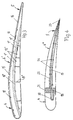
- FIG. 1 Device for changing the wing shape respectively the leaf profile or the planking of the wing one Aircraft is a flexurally elastic clamping beam 1 with the two carrier ends 2 and 3 in this way on the wing nose 4 and anchored to the wing end 5 of the carrier profile 6 that there is an arched, prestressed for this tensioning beam Carrier course results.
- the magnitude of the curvature depends on the mutual distance of the two wing-fixed anchorings of the tensioning beam as well from its initial length before mediating the tensioning beam of the two anchorages at the beam ends in the arched brought curved arrangement within the wing becomes.
- An optimal arch curvature of the tension member can be taking into account the aerodynamic conditions easily determine which the profile of the wing is subject to an arrangement in this determination of individual flexible webs or spars 7 and 8 can be included, through which the clamping bracket a support experienced on the paneling of the wing.
- the predetermined together with the profile of the wing Curvature of the tension member 1 is by a cable actuator 9 changeable.
- This cable actuator should preferably be designed according to EP 0 838 597 A1 received because it is the energy of an aircraft generally available working fluids in one mechanical force can be converted, namely in the present Fall in an axial traction with which the haul-in is made possible by two pull cables 10 and 11 with which that is, a change in the curvature of the tension member 1 can be obtained.
- the two traction cables 10 and 11 For this change in the curvature of the tension member 1 are the two traction cables 10 and 11 with a first end the two wing-fixed anchorages of the tensioning beam 1 attached.
- the attachment is made at one point for which when pulling the pull ropes through the Tractive forces that are attached to each other at the fastening ends of the traction ropes counteract axially, a smooth and energy-saving Change in the curvature of the tendon is obtained.
- the tensile forces are over the second attachment end the pull cables 10 and 11 received on two tie rods attached to the both axial ends of a substantially tubular expansion chamber of the cable actuator 9 are arranged.
- the expansion chamber consists of an elastic and flexible Material and can therefore be applied to a an internal pressure imparted by a working fluid essentially experience radially oriented deformation on a transmit power transmission envelope surrounding the expansion chamber which is made of a flexible but not stretchable and thread material formed with a continuous thread consists.
- the tie rods are on the transmission sleeve attached so that there is an increase in the internal pressure in the Expansion chamber in the generation of axially counteracting Tensile forces affects the tie rods to the two Pull ropes 10 and 11 are passed on.
- the pull ropes, the through individual cable guides 12 along the tensioning beam 1 lead, therefore, bring about a mutual approximation of the two ends of the tension member and thus lead to a change its curvature.
- FIG. 2 there is a match Arrangement of a flexible support 1 'and one also matching cable actuator 9 'with the two pull cables 10 'and 11' realized.
- a flexible support 1 'and one also matching cable actuator 9 'with the two pull cables 10 'and 11' realized.
- Different from the embodiment of Fig. 1 is the lack of flexurally elastic Bars or spars 7,8 and their replacement by a permanently elastic, preferably large-pored foam 13 Wing shell to provide a comparable support for the To obtain tensioning beam on the planking of the beam profile 6 '.
- the support function of the foam 13 can still can be supplemented by additional bars or spars taking into account the primarily intended change option the wing shape by changing the curvature of the tension member 1 ', which again by a adapted arrangement of cable guides 12 'is influenced.
- Fig. 3 is a support of the Clamping bracket 1 '' over webs or bars 8 '' opposite the pressure side the planking provided.
- the just two pull-in ropes 15 and 16 has, the first ends here directly on the planking are attached.
- the pull ropes 15 and 16 are also through Rope guides 17 out, their distribution and training is strategically predetermined in such a way that here too by a mutually influencing effect of the two cable actuators 9 '' and 14 an adaptive change option of the carrier profile 6 '' for finding optimal buoyancy conditions is achievable.
- Fig. 4 is a cable actuator 18 of the different training with only one catchable Traction rope 19 provided.
- the actuator 18 provided with an abutment 20, which is close to the Wing nose is arranged on a separate support beam 21.
- this support beam 21 on which also the planking the wing is attached, one end continues of a tensioning beam that is also designed to be flexible 22 anchored, the other end by one at the wing end arranged end bar 23 together with the free end of the Pull rope 19 is anchored.
- the pull rope 19 guided by cable guides 24, which run along the tension member 22 spaced apart and partially are differently designed such that for the traction rope 19 different guide distances perpendicular to the clamping bracket 22 can be obtained.
- the cable actuator 18 is in remaining functionally equivalent to that for the embodiment 1 described actuator, wherein for a Another alternative embodiment can also be considered can that a second pull rope for a connection of the actuator with the abutment could be provided.
- the device according to the invention is except for the wing (Shell wing) of an aircraft also applicable to others comparable flow profiles, for example also for ship propellers or generally for the blading of turbomachines.
- the rotors for example, are also used as wings understood by helicopters, where a comparable Profile is realized.
- a cable pull actuator the preferred embodiment according to the invention according to the Other actuators can also be provided in EP 0 838 597 A1 are recognized if there is a different expediency should be.
- the Sash size is of course decisive for the number and also for the arrangement and, if necessary, different training of the facilities provided according to the invention each with at least one flexurally elastic clamping beam and an associated cable actuator are so that at least a portion of the wing shape by changing the curvature of the tension member to be able to adaptively change.
- the tensioning bracket can also be used integrated branches that are immediate Support the planking and give the wing shape also change directly if their indirect change with a change in the curvature of the tension member is set.
Landscapes
- Engineering & Computer Science (AREA)
- Mechanical Engineering (AREA)
- Aviation & Aerospace Engineering (AREA)
- Installation Of Indoor Wiring (AREA)
- Structures Of Non-Positive Displacement Pumps (AREA)
- Actuator (AREA)
Applications Claiming Priority (2)
| Application Number | Priority Date | Filing Date | Title |
|---|---|---|---|
| DE29817162U DE29817162U1 (de) | 1998-09-24 | 1998-09-24 | Einrichtung bei einem Tragflügel eines Luftfahrzeuges zur Veränderung der Flügelform |
| DE29817162U | 1998-09-24 |
Publications (2)
| Publication Number | Publication Date |
|---|---|
| EP0989057A2 true EP0989057A2 (fr) | 2000-03-29 |
| EP0989057A3 EP0989057A3 (fr) | 2001-04-04 |
Family
ID=8063091
Family Applications (1)
| Application Number | Title | Priority Date | Filing Date |
|---|---|---|---|
| EP99117380A Withdrawn EP0989057A3 (fr) | 1998-09-24 | 1999-09-03 | Dispositif pour changer la forme de l'aile d'un aéronef |
Country Status (2)
| Country | Link |
|---|---|
| EP (1) | EP0989057A3 (fr) |
| DE (1) | DE29817162U1 (fr) |
Cited By (3)
| Publication number | Priority date | Publication date | Assignee | Title |
|---|---|---|---|---|
| FR2898865A1 (fr) * | 2006-03-27 | 2007-09-28 | Cetim Cermat Ass Loi De 1901 | Profil aerodynamique ou hydrodynamique pouvant etre deforme de maniere continue et controlee |
| RU2706678C1 (ru) * | 2018-10-26 | 2019-11-19 | Общество с ограниченной ответственностью "Тулаев-Парк" | Адаптивная аэродинамическая структура и крыло летательного аппарата на ее основе |
| CN117885887A (zh) * | 2024-03-14 | 2024-04-16 | 成都航空职业技术学院 | 一种折扭耦合仿生机翼及仿生飞行器 |
Families Citing this family (2)
| Publication number | Priority date | Publication date | Assignee | Title |
|---|---|---|---|---|
| GB201115860D0 (en) * | 2011-09-14 | 2011-10-26 | Rolls Royce Plc | A variable geometry structure |
| EP2769911A3 (fr) * | 2013-02-22 | 2017-08-16 | Herbert Kotschnig | Longeron d'aile démontable pour ailerons porteurs notamment également démontables ou objets aérodynamiques semblables à une aile |
Citations (1)
| Publication number | Priority date | Publication date | Assignee | Title |
|---|---|---|---|---|
| EP0838597A1 (fr) | 1996-10-22 | 1998-04-29 | Werner Homann | Actionneur pour transformer l'énergie d'un fluide en force mécanique |
Family Cites Families (5)
| Publication number | Priority date | Publication date | Assignee | Title |
|---|---|---|---|---|
| DE471694C (de) * | 1929-02-15 | Hermann Hahn | Flugzeug mit biegsamer Tragflaeche | |
| GB190920173A (en) * | 1909-09-03 | 1910-08-18 | William Tattersall | Improvements in and relating to the Construction of Wings or Organs for the Sustention and Flight of Aerial Vessels or Flying Machines. |
| FR549141A (fr) * | 1922-03-20 | 1923-02-02 | Voilure à courbure variable | |
| US4349169A (en) * | 1980-08-14 | 1982-09-14 | The United States Of America As Represented By The Secretary Of The Air Force | Continuous force actuator |
| US5367970A (en) * | 1993-09-27 | 1994-11-29 | The United States Of America As Represented By The Secretary Of The Navy | Controllable camber fin |
-
1998
- 1998-09-24 DE DE29817162U patent/DE29817162U1/de not_active Expired - Lifetime
-
1999
- 1999-09-03 EP EP99117380A patent/EP0989057A3/fr not_active Withdrawn
Patent Citations (1)
| Publication number | Priority date | Publication date | Assignee | Title |
|---|---|---|---|---|
| EP0838597A1 (fr) | 1996-10-22 | 1998-04-29 | Werner Homann | Actionneur pour transformer l'énergie d'un fluide en force mécanique |
Cited By (5)
| Publication number | Priority date | Publication date | Assignee | Title |
|---|---|---|---|---|
| FR2898865A1 (fr) * | 2006-03-27 | 2007-09-28 | Cetim Cermat Ass Loi De 1901 | Profil aerodynamique ou hydrodynamique pouvant etre deforme de maniere continue et controlee |
| WO2007110518A1 (fr) * | 2006-03-27 | 2007-10-04 | Cetim Cermat (Association) | Profil aerodynamique ou hydrodynamique pouvant être deforme de maniere continue et controlee |
| RU2706678C1 (ru) * | 2018-10-26 | 2019-11-19 | Общество с ограниченной ответственностью "Тулаев-Парк" | Адаптивная аэродинамическая структура и крыло летательного аппарата на ее основе |
| CN117885887A (zh) * | 2024-03-14 | 2024-04-16 | 成都航空职业技术学院 | 一种折扭耦合仿生机翼及仿生飞行器 |
| CN117885887B (zh) * | 2024-03-14 | 2024-05-14 | 成都航空职业技术学院 | 一种折扭耦合仿生机翼及仿生飞行器 |
Also Published As
| Publication number | Publication date |
|---|---|
| EP0989057A3 (fr) | 2001-04-04 |
| DE29817162U1 (de) | 1999-01-07 |
Similar Documents
| Publication | Publication Date | Title |
|---|---|---|
| DE69204536T2 (de) | Flugzeugfahrwerk mit aus einem faserverstärktem Kunststoff gefertigten Querträger. | |
| DE3103710C2 (de) | "Rotor in Schalenbauweise" | |
| DE2021040A1 (de) | Laststabilisierungsvorrichtung | |
| DE2348304C3 (de) | Strömungskörper zur Beeinflussung strömender Medien | |
| EP3022116B1 (fr) | Profil d'aile variable | |
| EP0869062B1 (fr) | Support de turbine, en particulier pour aéronefs à hélice, avec une ossature pour la fixation de la turbine | |
| DE1756929A1 (de) | Rotorfluegel | |
| DE3342861A1 (de) | Verbesserungen an flugkoerpern und anderen ruempfen | |
| EP0947693A2 (fr) | Profil de pale pour éolienne | |
| DE102009050747A1 (de) | Flugzeug mit mindestens zwei Seitenleitwerken in nicht zentraler Anordnung | |
| EP1312545A2 (fr) | Profil aérodynamique avec volet actionnable | |
| DE102009003084B4 (de) | Verkleidung für eine Auftriebshilfe | |
| EP0989057A2 (fr) | Dispositif pour changer la forme de l'aile d'un aéronef | |
| DE2905221C2 (de) | Blaswerk für schützenlose Webmaschinen | |
| DE2701482A1 (de) | Tandemfluegel-flugzeug | |
| EP0909703B1 (fr) | Gouvernail pour bateaux | |
| DE102014103999A1 (de) | Rahmeneinrichtung für eine Profilsegeleinrichtung und Profilsegeleinrichtung | |
| DE102012102746A1 (de) | Rotorblatt mit adaptivem Vorflügel für eine Windenergieanlage | |
| DE102020105899A9 (de) | Fluggerät mit mehreren Flugmodi und Verfahren zu dessen Betreiben | |
| DE1021249B (de) | Einrichtung an Quertriebsflaechen, insbesondere Luftfahrzeugfluegeln | |
| EP1659200B1 (fr) | Barre pour cadre à lisses | |
| DE102007020952A1 (de) | Tragflügel für ein Luftfahrzeug mit einer in Faserverbundbauweise ausgebildeten tragenden Struktur | |
| DE830896C (de) | Flugzeug | |
| DE3516998C2 (fr) | ||
| DE69011308T2 (de) | Gerät und Verfahren zur Reduzierung des Flatterns einer tragenden Fläche eines Flugzeuges. |
Legal Events
| Date | Code | Title | Description |
|---|---|---|---|
| PUAI | Public reference made under article 153(3) epc to a published international application that has entered the european phase |
Free format text: ORIGINAL CODE: 0009012 |
|
| AK | Designated contracting states |
Kind code of ref document: A2 Designated state(s): AT BE CH CY DE DK ES FI FR GB GR IE IT LI LU MC NL PT SE |
|
| AX | Request for extension of the european patent |
Free format text: AL;LT;LV;MK;RO;SI |
|
| PUAL | Search report despatched |
Free format text: ORIGINAL CODE: 0009013 |
|
| AK | Designated contracting states |
Kind code of ref document: A3 Designated state(s): AT BE CH CY DE DK ES FI FR GB GR IE IT LI LU MC NL PT SE |
|
| AX | Request for extension of the european patent |
Free format text: AL;LT;LV;MK;RO;SI |
|
| AKX | Designation fees paid | ||
| REG | Reference to a national code |
Ref country code: DE Ref legal event code: 8566 |
|
| STAA | Information on the status of an ep patent application or granted ep patent |
Free format text: STATUS: THE APPLICATION IS DEEMED TO BE WITHDRAWN |
|
| 18D | Application deemed to be withdrawn |
Effective date: 20011005 |