EP0989450A2 - Overhead-Projektor mit Vibrationsdämpfung des Projektionskopfes - Google Patents
Overhead-Projektor mit Vibrationsdämpfung des Projektionskopfes Download PDFInfo
- Publication number
- EP0989450A2 EP0989450A2 EP99123471A EP99123471A EP0989450A2 EP 0989450 A2 EP0989450 A2 EP 0989450A2 EP 99123471 A EP99123471 A EP 99123471A EP 99123471 A EP99123471 A EP 99123471A EP 0989450 A2 EP0989450 A2 EP 0989450A2
- Authority
- EP
- European Patent Office
- Prior art keywords
- head
- mounting plate
- bracket
- projection
- head bracket
- Prior art date
- Legal status (The legal status is an assumption and is not a legal conclusion. Google has not performed a legal analysis and makes no representation as to the accuracy of the status listed.)
- Granted
Links
Images


Classifications
-
- G—PHYSICS
- G03—PHOTOGRAPHY; CINEMATOGRAPHY; ANALOGOUS TECHNIQUES USING WAVES OTHER THAN OPTICAL WAVES; ELECTROGRAPHY; HOLOGRAPHY
- G03B—APPARATUS OR ARRANGEMENTS FOR TAKING PHOTOGRAPHS OR FOR PROJECTING OR VIEWING THEM; APPARATUS OR ARRANGEMENTS EMPLOYING ANALOGOUS TECHNIQUES USING WAVES OTHER THAN OPTICAL WAVES; ACCESSORIES THEREFOR
- G03B21/00—Projectors or projection-type viewers; Accessories therefor
- G03B21/132—Overhead projectors, i.e. capable of projecting hand-writing or drawing during action
-
- Y—GENERAL TAGGING OF NEW TECHNOLOGICAL DEVELOPMENTS; GENERAL TAGGING OF CROSS-SECTIONAL TECHNOLOGIES SPANNING OVER SEVERAL SECTIONS OF THE IPC; TECHNICAL SUBJECTS COVERED BY FORMER USPC CROSS-REFERENCE ART COLLECTIONS [XRACs] AND DIGESTS
- Y10—TECHNICAL SUBJECTS COVERED BY FORMER USPC
- Y10S—TECHNICAL SUBJECTS COVERED BY FORMER USPC CROSS-REFERENCE ART COLLECTIONS [XRACs] AND DIGESTS
- Y10S353/00—Optics: image projectors
- Y10S353/06—Head accessories
Definitions
- the present invention relates generally to overhead projectors, and more specifically to overhead projectors that are used to transmit images from liquid crystal display panels.
- the invention relates to improvements in overhead projection heads to reduce vibration and blurring of the projected image.
- Overhead projectors of the transmissive type include a base unit which encloses a light source and lenses for suitably focusing light from the source and a transparent stage upon which may be positioned a transparency or other film having indicia which is to be projected on a distant screen. Above the base is disposed a projection head having lenses and a mirror which function to gather light from the projector base and redirect it to the screen. The projection head is supported by a post or arm extending upwardly from the base.
- the primary structural member of the projection head assembly is attached directly to the arm in a cantilevered fashion by screws positioned near the rear edge of the head bracket.
- the head bracket supports the projection lens and the mirror, as well as a head cover.
- the technical problem addressed by this invention is the occurrence of undesirable vibration in the head of an overhead projector, such as when the projector is used with a liquid crystal display (LCD) panel.
- LCD liquid crystal display
- a LCD panel is used to allow projection of a computer-generated image by an overhead projector.
- the cooling fan of the LCD panel causes an unacceptable resonant vibration of the projection head of the overhead projector. This vibration of the head, and the mirror in the head, in particular, causes unacceptable smearing or blurring of the projected image.
- the present invention provides an improved projector head for an overhead projector, and particularly for an overhead projector that is used to project an image from an LCD panel.
- the improvement made to the projector head changes the resonant modes of the head so as to remove them from the driving frequencies generated by fans in the projector and in the LCD panel.
- the improvement comprises the addition of a mounting plate that is positioned between the head bracket and the head support arm.
- the mounting plate is attached to the arm in a cantilevered fashion, such as by screws located near the rear edge of the mounting plate.
- the head bracket is attached to the mounting plate at a location spaced from the rear edge of the mounting plate.
- the location of attachment between the mounting plate and the head bracket may be near the front edge of the mounting plate and near the centerline of the head bracket.
- the location of attachment between the mounting plate and the head bracket may be at other positions on each component as well.
- the benefits of the invention may be realized by splitting the head bracket into a lens bracket and a separate mirror bracket, and attaching those two brackets to one another in a semi-rigid manner.
- An energy absorbing material may be placed between the lens bracket and the mirror bracket to de-couple the mirror assembly from the remainder of the overhead projector.
- Such a split-head assembly may be used by itself, or it may be used in conjunction with the mounting plate described in the preceding paragraph.
- the present invention therefore provides an improved overhead projector head assembly which eliminates or reduces the occurrence of unacceptable vibration of the projection mirror and consequent blurring of the projected image.
- Figure 1 illustrates a typical transmissive type overhead projector, generally indicated as 10, which includes as major elements a base 12, an upright post 14 extending from the base 12, an adjustment mechanism 16 attached to the post 14 and a focus arm 18 extending from the adjustment mechanism 16 to support a projection head 20.
- the projection head 20 includes a lens or plurality of lenses 22 and a mirror 24 and is supported so that the lens 22 is positioned over a transparent stage 26.
- the base 12 of the projector 10 houses a light source, mirrors and lenses which direct light through the stage 26 and an imaging film such as a transparency located thereon and focus that light at the lens 22 of the projection head 20.
- the light passing through the projection head lens 22 is redirected by the mirror 24 to a distant vertical surface which is or serves as a screen for the projected image.
- a computer driven imaging display device such as a liquid crystal display (LCD) panel
- LCD liquid crystal display
- the LCD panel is used by positioning it on stage 26 in place of a transparency.
- LCD panels suitable for this application typically include cooling fans that can induce vibration into the overhead projector system. In some combinations of overhead projectors and LCD panels, it has been observed that unacceptable smearing or blurring of the projected image occurs. That problem has been identified as being caused by the existence of a resonant mode in the projection head corresponding to a vibration frequency generated by a typical LCD display fan.
- Vibration frequencies can also be generated by the overhead projector fan and interactions between the overhead projector fan, the LCD panel fan and other sources.
- Figure 2 illustrates a prior art projection head structure. This drawing is intended to represent a typical arrangement of components, but it is particularly representative of some typical projection heads as are known in the prior art.
- the components of the projection head are assembled on head bracket 30 which has front end 32 and rear end 31. Head bracket 30 is attached to support arm 18 in a cantilevered fashion near rear edge 31. Head bracket 30 typically supports projection lens 22 and projection mirror 24, as well as a head cover (not shown).
- FIG. 3 a preferred embodiment of the present invention is illustrated wherein the head bracket 30 as shown in Figure 2 is connected to arm 18 via mounting plate 34 and spacer 36.
- mounting plate 34 is attached to arm 18 in a cantilevered fashion.
- Mounting plate 34 is generally horizontally disposed.
- Head bracket 30 is attached to and supported by mounting plate 34.
- the point of attachment between mounting plate 34 and head bracket 30 is spaced from arm 18.
- mounting- plate 34 and head bracket 32 are attached at two locations, one on each lateral side of projection lens 22. A line connecting those two points of attachment may approximate a center of balance of projection head assembly including head bracket 30, projection lens 22 and mirror 24.
- Spacer 36 may comprise a rigid material such as aluminum or other metal or plastic, or it may comprise a resilient material such as rubber, soft plastic or a foam material.
- FIG. 4 provides an exploded view of a presently preferred embodiment of the present invention.
- Mounting plate 34 is attached to arm 18 by screws 42.
- Head bracket 30 is attached to mounting plate 34 at a location spaced from arm 18.
- a travel limiting tab 38 may be formed in mounting plate 34 for engagement with slot 44 formed in head bracket 30.
- Dampening pad 40 may also be placed between mounting plate 34 and head bracket 30 in the vicinity of travel limiting tab 38. Travel limiting tab 38 and dampening pad 40 cooperate to restrict and dampen any relative motion of head bracket 30 with respect to mounting plate 34, particularly to reduce the settling time of any impact-induced transient vibrations, such as when the projector is bumped by the user.
- Projection lens (not shown) is suspended within orifice 48 of head bracket 30, and the projection mirror (not shown) is supported by the vertical panel portions 50 of head bracket 30.
- Head cover 46 is also attached to head bracket 30.
- spacer 36 is made of aluminum and dampening pad 40 consists of a small block of a shock absorbing or dampening material, which may be E-A-R ISOLOSS® "LS" high density cellular urethane foam.
- Figure 5 illustrates an alternative embodiment of the present invention.
- Figure 5 is similar in most respects to Figure 3, except that mounting plate 34 is substantially longer, extending as far forward as the front edge 32 of head bracket 30.
- the point of attachment between mounting plate 34 and head bracket 30 is near the front edge of both components, with spacers positioned between the mounting plate 34 and head bracket 30 to separate them from one another.
- Head bracket 30 is thus cantilevered back in a rearward direction from spacer 36.
- One or more travel limiting tabs and/or dampening pads, as described above, may be employed in this embodiment between mounting plate 34 and head bracket 30.
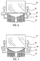
- Figures 6 and 7 illustrate further alternative embodiments of the present invention. Both of these figures show views from the front of the projector of lens 22 and mirror 24 supported by structures that isolate the mirror from the lens.
- Head bracket 52 supports lens 22 and is directly or indirectly attached to the projector arm (not shown).
- Mirror bracket 54 supports mirror 24.
- Mirror bracket 54 is attached to head bracket 52 through dampening material 56. This dampening material inhibits the transfer of vibrational energy from the overhead projector to mirror 24.
- Mirror bracket 54 and head bracket 52 may be joined together with screws, rivets or similar fasteners with dampening material 56 in the form of a washer or similar insert.
- the mirror bracket 54 and head bracket 52 may each be attached to dampening material 56 by adhesive or other means.
- the embodiment of Figure 7 is similar to the embodiment shown in Figure 6 except that dampening material 58 is disposed in a slanted position rather than in a horizontal position.
- Mirror bracket 54 and head bracket 52 are correspondingly altered as shown in the figure.
- an alternative method for reducing vibration of an overhead projector image is to add a rearward extension 60 to head bracket 30 and to place counterweight 62 on said rearward extension.
- counterweight 62 is located behind support arm 18, it tends to counterbalance the weight of lens 22 and the other components that are in front of support arm 18, thus moving the center of gravity of the head assembly rearward toward support arm 18. By moving the center of gravity the moments of inertia and the vibrational modes of the head assembly are altered. It will be apparent to one skilled in the art having the benefit of this description that an appropriate counterweight can be selected and positioned to eliminate or reduce resonant vibration problems in the projector head.
- the split-head design of the present invention provided a substantial decrease in the measured vibration of the projection mirror. Additional subjective tests based on observation of the vibration of the projected image have been consistent with these objective results, showing that the novel split-head design solves the problem of image vibration when a LCD panel causes unacceptable vibration when used with an overhead projector.
Landscapes
- Physics & Mathematics (AREA)
- General Physics & Mathematics (AREA)
- Overhead Projectors And Projection Screens (AREA)
- Projection Apparatus (AREA)
- Liquid Crystal (AREA)
- Instrument Panels (AREA)
Applications Claiming Priority (4)
| Application Number | Priority Date | Filing Date | Title |
|---|---|---|---|
| US401311 | 1995-03-15 | ||
| US08/401,311 US5465127A (en) | 1995-03-15 | 1995-03-15 | Overhead projector with vibration control head |
| PCT/US1996/001551 WO1996028759A1 (en) | 1995-03-15 | 1996-02-06 | Overhead projector with vibration control head |
| EP96906293A EP0815493B1 (de) | 1995-03-15 | 1996-02-06 | Overhead projektor mit vibrationsdämpfung des projektionskopfes |
Related Parent Applications (1)
| Application Number | Title | Priority Date | Filing Date |
|---|---|---|---|
| EP96906293A Division EP0815493B1 (de) | 1995-03-15 | 1996-02-06 | Overhead projektor mit vibrationsdämpfung des projektionskopfes |
Publications (3)
| Publication Number | Publication Date |
|---|---|
| EP0989450A2 true EP0989450A2 (de) | 2000-03-29 |
| EP0989450A3 EP0989450A3 (de) | 2000-04-12 |
| EP0989450B1 EP0989450B1 (de) | 2003-02-05 |
Family
ID=23587217
Family Applications (2)
| Application Number | Title | Priority Date | Filing Date |
|---|---|---|---|
| EP99123471A Expired - Lifetime EP0989450B1 (de) | 1995-03-15 | 1996-02-06 | Overhead-Projektor mit Vibrationsdämpfung des Projektionskopfes |
| EP96906293A Expired - Lifetime EP0815493B1 (de) | 1995-03-15 | 1996-02-06 | Overhead projektor mit vibrationsdämpfung des projektionskopfes |
Family Applications After (1)
| Application Number | Title | Priority Date | Filing Date |
|---|---|---|---|
| EP96906293A Expired - Lifetime EP0815493B1 (de) | 1995-03-15 | 1996-02-06 | Overhead projektor mit vibrationsdämpfung des projektionskopfes |
Country Status (8)
| Country | Link |
|---|---|
| US (1) | US5465127A (de) |
| EP (2) | EP0989450B1 (de) |
| JP (1) | JPH11502034A (de) |
| CN (3) | CN1100283C (de) |
| DE (2) | DE69626144T2 (de) |
| ES (2) | ES2148736T3 (de) |
| TW (1) | TW293095B (de) |
| WO (1) | WO1996028759A1 (de) |
Cited By (1)
| Publication number | Priority date | Publication date | Assignee | Title |
|---|---|---|---|---|
| US7114810B2 (en) | 2004-06-25 | 2006-10-03 | Hewlett-Packard Development Company, L.P. | Multimedia display device |
Families Citing this family (5)
| Publication number | Priority date | Publication date | Assignee | Title |
|---|---|---|---|---|
| US6443577B1 (en) * | 2000-12-15 | 2002-09-03 | 3M Innovative Properties Company | Overhead projection having a friction secured adjustable cantilevered head |
| CN100532885C (zh) * | 2004-04-27 | 2009-08-26 | 清展塑胶股份有限公司 | 用于门窗的啮合元件可简易行使反向直线运动驱动装置 |
| US7513627B2 (en) * | 2005-12-30 | 2009-04-07 | Honeywell International Inc. | Image projection system with vibration compensation |
| CN106292140A (zh) * | 2016-10-17 | 2017-01-04 | 上海科世达-华阳汽车电器有限公司 | 一种车用迎宾投影灯 |
| CN110925548A (zh) * | 2019-12-31 | 2020-03-27 | 苏州氶颂展览展示有限公司 | 一种投影仪防震支架 |
Family Cites Families (15)
| Publication number | Priority date | Publication date | Assignee | Title |
|---|---|---|---|---|
| US3472589A (en) * | 1965-10-23 | 1969-10-14 | Beseler Co Charles | Overhead projector |
| JPS5545887B2 (de) * | 1972-01-07 | 1980-11-20 | ||
| DE2420456A1 (de) * | 1974-04-24 | 1975-11-13 | Gerhard Ritzerfeld | Projektionskopf fuer einen tageslichtprojektor |
| DE3010497C2 (de) * | 1980-03-19 | 1982-05-06 | Fa. Ed. Liesegang, 4000 Düsseldorf | Arbeitsprojektor |
| US4634246A (en) * | 1985-04-01 | 1987-01-06 | Minnesota Mining And Manufacturing Company | Automatic focus for overhead projector |
| JPH01162378U (de) * | 1988-04-28 | 1989-11-13 | ||
| US4944578A (en) * | 1988-07-21 | 1990-07-31 | Telex Communications | Color graphic imager utilizing a liquid crystal display |
| US4986651A (en) * | 1989-08-04 | 1991-01-22 | Minnesota Mining And Manufacturing Company | Overhead projector with centerless Fresnel lens reflective stage |
| US4969733A (en) * | 1989-10-02 | 1990-11-13 | Dukane Corporation | Foldable portable overhead projector |
| DE9017123U1 (de) * | 1990-12-19 | 1991-03-14 | ProCent Patent- und Verwaltungs AG, Zürich | Schreibprojektor mit einer größeren und einer kleineren Arbeitsfläche |
| US5135301A (en) * | 1991-01-22 | 1992-08-04 | Minnesota Mining And Manufacturing Company | Reflective overhead projector with alternate light sources |
| JPH0695247A (ja) * | 1992-09-09 | 1994-04-08 | Fuji Photo Film Co Ltd | オーバーヘッドプロジェクタ |
| JP2877180B2 (ja) * | 1992-09-09 | 1999-03-31 | 富士写真フイルム株式会社 | オーバーヘッドプロジェクタ |
| US5245370A (en) * | 1992-10-22 | 1993-09-14 | Minnesota Mining And Manufacturing Company | Overhead projector focus arm adjustment mechanism |
| US5241333A (en) * | 1992-10-22 | 1993-08-31 | Minnesota Mining And Manufacturing Company | Overhead projector with pivoting lamp changer and color adjustment |
-
1995
- 1995-03-15 US US08/401,311 patent/US5465127A/en not_active Expired - Fee Related
- 1995-03-31 TW TW084103128A patent/TW293095B/zh not_active IP Right Cessation
-
1996
- 1996-02-06 ES ES96906293T patent/ES2148736T3/es not_active Expired - Lifetime
- 1996-02-06 CN CN96192582A patent/CN1100283C/zh not_active Expired - Fee Related
- 1996-02-06 WO PCT/US1996/001551 patent/WO1996028759A1/en not_active Ceased
- 1996-02-06 DE DE69626144T patent/DE69626144T2/de not_active Expired - Fee Related
- 1996-02-06 JP JP8527579A patent/JPH11502034A/ja not_active Ceased
- 1996-02-06 DE DE69609317T patent/DE69609317T2/de not_active Expired - Fee Related
- 1996-02-06 ES ES99123471T patent/ES2192015T3/es not_active Expired - Lifetime
- 1996-02-06 EP EP99123471A patent/EP0989450B1/de not_active Expired - Lifetime
- 1996-02-06 EP EP96906293A patent/EP0815493B1/de not_active Expired - Lifetime
-
2002
- 2002-01-25 CN CN02102855A patent/CN1389761A/zh active Pending
- 2002-01-25 CN CN02102854A patent/CN1389760A/zh active Pending
Cited By (1)
| Publication number | Priority date | Publication date | Assignee | Title |
|---|---|---|---|---|
| US7114810B2 (en) | 2004-06-25 | 2006-10-03 | Hewlett-Packard Development Company, L.P. | Multimedia display device |
Also Published As
| Publication number | Publication date |
|---|---|
| DE69626144D1 (de) | 2003-03-13 |
| TW293095B (de) | 1996-12-11 |
| DE69609317D1 (de) | 2000-08-17 |
| EP0989450A3 (de) | 2000-04-12 |
| EP0989450B1 (de) | 2003-02-05 |
| DE69609317T2 (de) | 2001-02-22 |
| JPH11502034A (ja) | 1999-02-16 |
| EP0815493A1 (de) | 1998-01-07 |
| US5465127A (en) | 1995-11-07 |
| DE69626144T2 (de) | 2003-12-04 |
| ES2192015T3 (es) | 2003-09-16 |
| CN1389760A (zh) | 2003-01-08 |
| ES2148736T3 (es) | 2000-10-16 |
| CN1389761A (zh) | 2003-01-08 |
| EP0815493B1 (de) | 2000-07-12 |
| WO1996028759A1 (en) | 1996-09-19 |
| CN1178586A (zh) | 1998-04-08 |
| CN1100283C (zh) | 2003-01-29 |
Similar Documents
| Publication | Publication Date | Title |
|---|---|---|
| US7513627B2 (en) | Image projection system with vibration compensation | |
| US20010000300A1 (en) | Desktop projection monitor | |
| JPH07508106A (ja) | デュアルイメージ頭部取り付け式表示装置 | |
| US7331678B2 (en) | Method and system for a thermal architecture and user adjustable keystone in a display device | |
| US5465127A (en) | Overhead projector with vibration control head | |
| JP2007114753A (ja) | 垂直位置に取り付けられた投写装置から画像を表示する装置及び方法 | |
| US6329965B1 (en) | Adjustable head mounted display apparatus and method of adjusting a head mounted display | |
| EP1424858A2 (de) | Farbradsicherung | |
| US6873479B2 (en) | Mounting bracket for a clear aperture of the base face of a prism | |
| US8876301B2 (en) | Video projection device easy for adjustment work | |
| JP2002077777A (ja) | 投写型映像表示装置の映像歪補正機構 | |
| HK1009856A (en) | Overhead projector with vibration control head | |
| RU2004123516A (ru) | Устройство для просмотра стереоскопического изображения, отображаемого видеодисплейным средством (варианты) | |
| CN211574711U (zh) | 一种投影仪防震支架 | |
| KR200339674Y1 (ko) | 프로젝션 텔레비전 | |
| EP1743480B1 (de) | Struktur zum anbringen einer licht-engine in einer projektionsanzeige | |
| US11422368B2 (en) | Head-up display apparatus and manufacturing meihod for vehicle | |
| GB2337134A (en) | Projector for LCD with lens supporting arm | |
| JP2571460Y2 (ja) | 液晶投射装置 | |
| JPS6097332A (ja) | 事務用投影機 | |
| JP2004326088A (ja) | 背面投射型プロジェクタ装置 | |
| JPH05122643A (ja) | プロジエクシヨンテレビのミラー取付構造 | |
| JP3088145U (ja) | 可動型背面投写型プロジェクター装置 | |
| JP3087322U (ja) | 可動型背面投写型プロジェクター装置 | |
| JP2021167860A (ja) | 投射型表示装置 |
Legal Events
| Date | Code | Title | Description |
|---|---|---|---|
| PUAI | Public reference made under article 153(3) epc to a published international application that has entered the european phase |
Free format text: ORIGINAL CODE: 0009012 |
|
| PUAL | Search report despatched |
Free format text: ORIGINAL CODE: 0009013 |
|
| AC | Divisional application: reference to earlier application |
Ref document number: 815493 Country of ref document: EP |
|
| AK | Designated contracting states |
Kind code of ref document: A2 Designated state(s): DE ES FR GB IT |
|
| AK | Designated contracting states |
Kind code of ref document: A3 Designated state(s): DE ES FR GB IT |
|
| 17P | Request for examination filed |
Effective date: 20000930 |
|
| AKX | Designation fees paid |
Free format text: DE ES FR GB IT |
|
| GRAG | Despatch of communication of intention to grant |
Free format text: ORIGINAL CODE: EPIDOS AGRA |
|
| 17Q | First examination report despatched |
Effective date: 20020415 |
|
| GRAG | Despatch of communication of intention to grant |
Free format text: ORIGINAL CODE: EPIDOS AGRA |
|
| GRAH | Despatch of communication of intention to grant a patent |
Free format text: ORIGINAL CODE: EPIDOS IGRA |
|
| GRAH | Despatch of communication of intention to grant a patent |
Free format text: ORIGINAL CODE: EPIDOS IGRA |
|
| GRAA | (expected) grant |
Free format text: ORIGINAL CODE: 0009210 |
|
| AC | Divisional application: reference to earlier application |
Ref document number: 0815493 Country of ref document: EP Kind code of ref document: P |
|
| AK | Designated contracting states |
Designated state(s): DE ES FR GB IT |
|
| REG | Reference to a national code |
Ref country code: GB Ref legal event code: FG4D |
|
| REF | Corresponds to: |
Ref document number: 69626144 Country of ref document: DE Date of ref document: 20030313 Kind code of ref document: P |
|
| PGFP | Annual fee paid to national office [announced via postgrant information from national office to epo] |
Ref country code: GB Payment date: 20030319 Year of fee payment: 8 Ref country code: FR Payment date: 20030319 Year of fee payment: 8 |
|
| PGFP | Annual fee paid to national office [announced via postgrant information from national office to epo] |
Ref country code: ES Payment date: 20030326 Year of fee payment: 8 |
|
| PGFP | Annual fee paid to national office [announced via postgrant information from national office to epo] |
Ref country code: DE Payment date: 20030331 Year of fee payment: 8 |
|
| REG | Reference to a national code |
Ref country code: ES Ref legal event code: FG2A Ref document number: 2192015 Country of ref document: ES Kind code of ref document: T3 |
|
| ET | Fr: translation filed | ||
| PLBE | No opposition filed within time limit |
Free format text: ORIGINAL CODE: 0009261 |
|
| STAA | Information on the status of an ep patent application or granted ep patent |
Free format text: STATUS: NO OPPOSITION FILED WITHIN TIME LIMIT |
|
| 26N | No opposition filed |
Effective date: 20031106 |
|
| PG25 | Lapsed in a contracting state [announced via postgrant information from national office to epo] |
Ref country code: GB Free format text: LAPSE BECAUSE OF NON-PAYMENT OF DUE FEES Effective date: 20040206 |
|
| PG25 | Lapsed in a contracting state [announced via postgrant information from national office to epo] |
Ref country code: ES Free format text: LAPSE BECAUSE OF NON-PAYMENT OF DUE FEES Effective date: 20040207 |
|
| PG25 | Lapsed in a contracting state [announced via postgrant information from national office to epo] |
Ref country code: DE Free format text: LAPSE BECAUSE OF NON-PAYMENT OF DUE FEES Effective date: 20040901 |
|
| GBPC | Gb: european patent ceased through non-payment of renewal fee |
Effective date: 20040206 |
|
| PG25 | Lapsed in a contracting state [announced via postgrant information from national office to epo] |
Ref country code: FR Free format text: LAPSE BECAUSE OF NON-PAYMENT OF DUE FEES Effective date: 20041029 |
|
| REG | Reference to a national code |
Ref country code: FR Ref legal event code: ST |
|
| PG25 | Lapsed in a contracting state [announced via postgrant information from national office to epo] |
Ref country code: IT Free format text: LAPSE BECAUSE OF NON-PAYMENT OF DUE FEES Effective date: 20050206 |
|
| REG | Reference to a national code |
Ref country code: ES Ref legal event code: FD2A Effective date: 20040207 |