EP0989773A2 - Dispositif de transducteur du son - Google Patents
Dispositif de transducteur du son Download PDFInfo
- Publication number
- EP0989773A2 EP0989773A2 EP99118504A EP99118504A EP0989773A2 EP 0989773 A2 EP0989773 A2 EP 0989773A2 EP 99118504 A EP99118504 A EP 99118504A EP 99118504 A EP99118504 A EP 99118504A EP 0989773 A2 EP0989773 A2 EP 0989773A2
- Authority
- EP
- European Patent Office
- Prior art keywords
- sound
- circuit board
- transducer
- opening
- sound transducer
- Prior art date
- Legal status (The legal status is an assumption and is not a legal conclusion. Google has not performed a legal analysis and makes no representation as to the accuracy of the status listed.)
- Withdrawn
Links
Images
Classifications
-
- H—ELECTRICITY
- H05—ELECTRIC TECHNIQUES NOT OTHERWISE PROVIDED FOR
- H05K—PRINTED CIRCUITS; CASINGS OR CONSTRUCTIONAL DETAILS OF ELECTRIC APPARATUS; MANUFACTURE OF ASSEMBLAGES OF ELECTRICAL COMPONENTS
- H05K1/00—Printed circuits
- H05K1/18—Printed circuits structurally associated with non-printed electric components
-
- H—ELECTRICITY
- H04—ELECTRIC COMMUNICATION TECHNIQUE
- H04R—LOUDSPEAKERS, MICROPHONES, GRAMOPHONE PICK-UPS OR LIKE ACOUSTIC ELECTROMECHANICAL TRANSDUCERS; ELECTRIC HEARING AIDS; PUBLIC ADDRESS SYSTEMS
- H04R3/00—Circuits for transducers
-
- H—ELECTRICITY
- H05—ELECTRIC TECHNIQUES NOT OTHERWISE PROVIDED FOR
- H05K—PRINTED CIRCUITS; CASINGS OR CONSTRUCTIONAL DETAILS OF ELECTRIC APPARATUS; MANUFACTURE OF ASSEMBLAGES OF ELECTRICAL COMPONENTS
- H05K2201/00—Indexing scheme relating to printed circuits covered by H05K1/00
- H05K2201/10—Details of components or other objects attached to or integrated in a printed circuit board
- H05K2201/10007—Types of components
- H05K2201/10083—Electromechanical or electro-acoustic component, e.g. microphone
Definitions
- the invention relates to a device for sound conversion with a sound transducer and a printed circuit board for carrying electrical components and contacts.
- Such devices are known in which a sound transducer, e.g. on Microphone or a playback converter (loudspeaker), for controlling an electronic one Circuit required, which is mounted on a circuit board part of the Device forms.
- a sound transducer e.g. on Microphone or a playback converter (loudspeaker)
- a playback converter for controlling an electronic one Circuit required, which is mounted on a circuit board part of the Device forms.
- a first group of such devices are cordless headphones, with soft ones in particular an RF or infrared receiving device and an amplifier device are arranged in close proximity to the playback converter.
- a playback converter is also used as well as a sensor microphone and a sensor microphone and control electronics needed to control a sound signal to be reproduced. In this case, too an attempt is made to control the control electronics together with the sound transducer in the To accommodate headphones for active sound insulation.
- a second group of such devices is wireless microphones formed, in which a sound transducer, in this case a microphone, in particular with a microphone amplifier device and an HF or infrared transmitter is combined.
- the acoustic properties of the playback transducer or the microphone for example, by their design or a suitably designed housing in which the sound transducer is arranged, deliberately influenced.
- a microphone can or a playback converter, for example, its directivity and its Transmission range can be specified or influenced.
- the object of the present invention is therefore an easy to assemble device to provide sound conversion, which is a comparatively simple Has structure.
- circuit board is an acoustic component for influencing the acoustic properties of the transducer.
- the advantages of the invention are in particular that additional for influencing the directivity and / or the transmission range of a sound transducer necessary housing parts saved and thus a significant reduction in Size of the device is achieved. Furthermore, a faster and cheaper assembly of the device achieved because after assembling the Sound converter and the control electronics electrical and acoustic components the device as a single manageable part. So is already too a very early point in the assembly process an acoustic and electronic components of the device possible before final assembly, for example in headphones.
- the circuit board is arranged in front of the sound opening of the sound transducer and a corresponding circuit board section covering the sound opening at least one breakthrough. A recording or delivery of sound waves thus takes place through those provided in the corresponding circuit board section Breakthrough. In an expedient further training, there are several openings provided in the corresponding circuit board section.
- the acoustic properties of the sound transducer can be determined in particular by Change the cross-sectional area of the openings, the thickness of the circuit board and the volume between the circuit board and the transducer.
- the device is advantageously designed such that the sound opening covering and having at least one opening circuit board section along with that between the transducer and the circuit board section formed cavity forms a resonator. By an appropriate Tuning the resonance frequency of the resonator allows the transmission and the phase behavior of the device for sound conversion to be specified.
- the opening is included covered with an acoustically damping material.
- the acoustically damping material can be, for example, silk or a fleece and is expediently on glued the surface of the circuit board facing away from the sound transducer. It is however also possible, the acoustically damping material through the opening to clamp or between the circuit board and a surrounding housing pinch.
- the acoustic properties can be determined by the one arranged before the opening further influence acoustically damping material. For example possible, resonance peaks of the formed by the sound transducer and the circuit board To dampen resonators in a targeted manner. In addition, by suitable acoustically damping material also influences the frequency response of the Take the device.
- the sound channel In a preferred embodiment is an extension to the opening a sound channel arranged.
- the length of the sound channel advantageously the resonance frequency of the between the transducer and the Tuning the circuit board formed resonator in a larger area.
- the sound channel has an outward widening Cross-sectional area through which in particular the directional characteristic of the transducer can be specified.
- the sound transducer is particularly preferably mechanical, in particular shaped or non-positive, connected to the circuit board.
- the transducer can be connected to the PCB welded, glued or screwed.
- a locking element provided on the sound transducer by a corresponding Breakthrough in the circuit board passes through and forms an abutment, so that the transducer is connected to the circuit board by means of a snap connection is.
- the sound transducer is in particular through a solder or plug connection with contacts on the circuit board connected.
- Such contacts simplify the assembly of the sound transducer on the printed circuit board, because with a mechanical coupling a electrical connection can be realized.
- the sound transducer provided in the device can either be a playback converter or a microphone. Of course it is too possible, both a playback converter and a microphone on a circuit board to attach in a manner according to the invention.
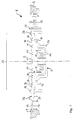
- Figure 1 shows a cross section through a portion of a headphone for active Soundproofing.
- a loudspeaker serving as a playback converter is shown 3
- a sensor microphone 5 for recording sound signals necessary for the control
- a printed circuit board 7 for housing sections 9.
- the loudspeaker comprises a membrane 11, which is connected to a voice coil 13 is a magnet 15 with an air gap in which the voice coil 13 is at least partially arranged, and a converter housing 17, which the Membrane 11 and the magnet 15 carries.
- the converter housing 17 further includes a locking extension 19 and a transducer contact 21.
- the locking extension 19 is designed such that this through a corresponding opening protrudes in the circuit board 17 and with the circuit board 7 an abutment forms.
- the converter contact 21 is on the one hand with the voice coil 13 and on the other hand with a corresponding contact on the circuit board 7 electrically connected.
- the circuit board 7 is fastened on both sides to housing sections 9 by in of the illustrated embodiment engages in the corresponding housing sections 9.
- the attachment can also be done, for example, by screwing or gluing respectively.
- the loudspeaker 3 is with its sound opening for emitting sound waves arranged directly on a surface of the circuit board 7 and there with With the help of locking extensions 19 attached.
- the locking extensions 19 can for example clamped in the circuit board or glued to it.
- the speaker 3 is connected to the circuit board 7, the Contacts 21 can also serve as fasteners.
- the sound opening of the speaker 3 covering circuit board section 23 are first Openings 25 for influencing the acoustic properties of the loudspeaker 3 arranged.
- On the speaker 3 opposite or facing side of the circuit board 7 is an acoustically damping material 26, for example made of silk or fleece, so that the first openings 25 are covered; these openings 25 can, however, at least in part also exposed.
- the sensor microphone 5 is arranged centrally on the circuit board section 23. In the Edge region of the circuit board section 23 and on the remaining sections of the Printed circuit board 7, electrical components 27 are provided. Furthermore, the circuit board 7 second openings 29, which also by an acoustically damping Material 26 can be at least partially covered.
- the one that covers the sound opening and has the first openings 25 PCB section 23 forms together with that between the membrane 11 of the speaker 3 and the circuit board portion 23 formed cavity 31st a resonator.
- the acoustic behavior of the resonator can be in the essentially by changing the size of the cavity 31, the cross-sectional area of the first openings 25 and the thickness of the printed circuit board 7.
Landscapes
- Engineering & Computer Science (AREA)
- Physics & Mathematics (AREA)
- Acoustics & Sound (AREA)
- Signal Processing (AREA)
- Microelectronics & Electronic Packaging (AREA)
- Electrostatic, Electromagnetic, Magneto- Strictive, And Variable-Resistance Transducers (AREA)
- Headphones And Earphones (AREA)
- Amplifiers (AREA)
- Signal Processing Not Specific To The Method Of Recording And Reproducing (AREA)
Applications Claiming Priority (2)
| Application Number | Priority Date | Filing Date | Title |
|---|---|---|---|
| DE19843731A DE19843731C2 (de) | 1998-09-24 | 1998-09-24 | Vorrichtung zur Schallwandlung |
| DE19843731 | 1998-09-24 |
Publications (2)
| Publication Number | Publication Date |
|---|---|
| EP0989773A2 true EP0989773A2 (fr) | 2000-03-29 |
| EP0989773A3 EP0989773A3 (fr) | 2000-04-05 |
Family
ID=7882033
Family Applications (1)
| Application Number | Title | Priority Date | Filing Date |
|---|---|---|---|
| EP99118504A Withdrawn EP0989773A3 (fr) | 1998-09-24 | 1999-09-18 | Dispositif de transducteur du son |
Country Status (4)
| Country | Link |
|---|---|
| US (1) | US20030103641A1 (fr) |
| EP (1) | EP0989773A3 (fr) |
| DE (1) | DE19843731C2 (fr) |
| IL (1) | IL132018A0 (fr) |
Cited By (2)
| Publication number | Priority date | Publication date | Assignee | Title |
|---|---|---|---|---|
| CN109753191A (zh) * | 2017-11-03 | 2019-05-14 | 迪尔阿扣基金两合公司 | 一种声学触控系统 |
| DE102011079707B4 (de) * | 2011-07-25 | 2024-11-14 | Robert Bosch Gmbh | Verfahren und Vorrichtung zur Erfassung von Objekten aus der Fahrzeugumgebung eines Fahrzeuges |
Families Citing this family (8)
| Publication number | Priority date | Publication date | Assignee | Title |
|---|---|---|---|---|
| KR100544282B1 (ko) * | 2004-02-24 | 2006-01-23 | 주식회사 비에스이 | 평행육면체형 콘덴서 마이크로폰 |
| US8483776B2 (en) * | 2005-07-27 | 2013-07-09 | Sony Corporation | Acoustic path for a wireless communications device |
| US8259982B2 (en) * | 2007-04-17 | 2012-09-04 | Hewlett-Packard Development Company, L.P. | Reducing acoustic coupling to microphone on printed circuit board |
| CN214544639U (zh) * | 2020-11-02 | 2021-10-29 | 瑞声科技(新加坡)有限公司 | 一种扬声器箱 |
| TW202425666A (zh) | 2022-12-02 | 2024-06-16 | 奧地利商優聲股份有限公司 | 音頻轉換單元 |
| DE102023104024A1 (de) * | 2022-12-02 | 2024-06-13 | USound GmbH | Schallwandlereinheit |
| TW202425668A (zh) | 2022-12-02 | 2024-06-16 | 奧地利商優聲股份有限公司 | 音頻轉換單元 |
| JP2024080655A (ja) | 2022-12-02 | 2024-06-13 | ユーサウンド ゲーエムベーハー | 音響トランスデューサユニット |
Family Cites Families (6)
| Publication number | Priority date | Publication date | Assignee | Title |
|---|---|---|---|---|
| NL7802687A (nl) * | 1978-03-13 | 1979-09-17 | Philips Nv | Dreunvrije microfooncombinatie bevattende twee microfoonelementen. |
| GB8328789D0 (en) * | 1983-10-27 | 1983-12-29 | Atomic Energy Authority Uk | Ultrasonic transducer assembly |
| US4922542A (en) * | 1987-12-28 | 1990-05-01 | Roman Sapiejewski | Headphone comfort |
| FR2673800B1 (fr) * | 1991-03-07 | 1993-12-31 | Lan Yan Fock Alain | Dispositif electro-acoustique de reproduction sonore, asservi electroniquement, utilisant un haut-parleur a pavillon muni de microphones. |
| DE4310793A1 (de) * | 1993-04-02 | 1994-10-06 | Ceotronics Gmbh Elektronische | Körperschall-Mikrofon für Schutzhelme oder dergleichen |
| DE4319599C1 (de) * | 1993-06-14 | 1994-08-25 | Siemens Audiologische Technik | Hörgerät |
-
1998
- 1998-09-24 DE DE19843731A patent/DE19843731C2/de not_active Expired - Fee Related
-
1999
- 1999-09-18 EP EP99118504A patent/EP0989773A3/fr not_active Withdrawn
- 1999-09-21 US US09/400,241 patent/US20030103641A1/en not_active Abandoned
- 1999-09-23 IL IL13201899A patent/IL132018A0/xx unknown
Cited By (2)
| Publication number | Priority date | Publication date | Assignee | Title |
|---|---|---|---|---|
| DE102011079707B4 (de) * | 2011-07-25 | 2024-11-14 | Robert Bosch Gmbh | Verfahren und Vorrichtung zur Erfassung von Objekten aus der Fahrzeugumgebung eines Fahrzeuges |
| CN109753191A (zh) * | 2017-11-03 | 2019-05-14 | 迪尔阿扣基金两合公司 | 一种声学触控系统 |
Also Published As
| Publication number | Publication date |
|---|---|
| EP0989773A3 (fr) | 2000-04-05 |
| IL132018A0 (en) | 2001-03-19 |
| DE19843731C2 (de) | 2001-10-25 |
| DE19843731A1 (de) | 2000-04-13 |
| US20030103641A1 (en) | 2003-06-05 |
Similar Documents
| Publication | Publication Date | Title |
|---|---|---|
| DE3525724C2 (fr) | ||
| DE60221857T2 (de) | Akustischen Miniwandler | |
| EP3799440A1 (fr) | Unité de convertisseur permettant de générer et/ou de d'enregistrer des ondes sonores dans la plage de longueurs d'onde audibles et/ou dans la plage ultrasonore | |
| DE102011015569A1 (de) | Kopfhörer | |
| EP1301012B1 (fr) | Dispositif de communication électronique mobile avec haut-parleur plat arrangé dans le boítier du dispositif et un haut-parleur additionnel arrangé dans un system de haut-parleur a deux voies avec le haut-parleur plat | |
| DE19843731C2 (de) | Vorrichtung zur Schallwandlung | |
| DE19620010B4 (de) | Lautsprechersystem mit Satellitengehäuse | |
| DE69203460T2 (de) | Lautsprecher. | |
| DE69112473T2 (de) | Lautsprecheranordnung und TV mit solcher Anordnung. | |
| EP3322032A1 (fr) | Appareil de correction auditive pourvu de cadre électronique et d'antenne intégrée audit appareil | |
| EP3209032A1 (fr) | Module de haut-parleur pour un appareil auditif et appareil auditif | |
| EP4054208A1 (fr) | Appareil auditif, antenne pour un appareil auditif et procédé de fabrication d'un appareil auditif | |
| EP3826327B1 (fr) | Appareil auditif | |
| EP0896497A2 (fr) | Sistème de reproduction de son | |
| DE102019219484B4 (de) | Leiterplatte eines Hörgeräts | |
| DE3916031A1 (de) | Aktive daempfungsvorrichtung fuer schwingungen, insbesondere in form von laerm, ohne akustische verzoegerung | |
| DE3927797A1 (de) | Im-ohr-hoergeraet mit schall-ausgleichskanal | |
| DE602004002685T2 (de) | Lautsprecher | |
| EP1339204B1 (fr) | Disposition de contacts pour microphone électrostatique | |
| DE10033576A1 (de) | Piezoelektrischer elektroakustischer Wandler | |
| EP2911312B1 (fr) | Antenne dotée de dispositif de protection et procédé de fabrication | |
| DE3101264C2 (de) | Kunstkopf | |
| DE102015217741A1 (de) | Akustischer Sensor zum Aussenden und Empfangen von akustischen Signalen und Verfahren zum Herstellen eines solchen Sensors | |
| EP3863305B1 (fr) | Appareil auditif | |
| DE1179257B (de) | Klangtreuer Lautsprecher |
Legal Events
| Date | Code | Title | Description |
|---|---|---|---|
| PUAI | Public reference made under article 153(3) epc to a published international application that has entered the european phase |
Free format text: ORIGINAL CODE: 0009012 |
|
| PUAL | Search report despatched |
Free format text: ORIGINAL CODE: 0009013 |
|
| AK | Designated contracting states |
Kind code of ref document: A2 Designated state(s): AT BE CH CY DE DK ES FI FR GB GR IE IT LI LU MC NL PT SE |
|
| AX | Request for extension of the european patent |
Free format text: AL;LT;LV;MK;RO;SI |
|
| AK | Designated contracting states |
Kind code of ref document: A3 Designated state(s): AT BE CH CY DE DK ES FI FR GB GR IE IT LI LU MC NL PT SE |
|
| AX | Request for extension of the european patent |
Free format text: AL;LT;LV;MK;RO;SI |
|
| AKX | Designation fees paid | ||
| REG | Reference to a national code |
Ref country code: DE Ref legal event code: 8566 |
|
| STAA | Information on the status of an ep patent application or granted ep patent |
Free format text: STATUS: THE APPLICATION IS DEEMED TO BE WITHDRAWN |
|
| 18D | Application deemed to be withdrawn |
Effective date: 20001006 |