EP0990101B1 - Verfahren zum transport von sauergas - Google Patents
Verfahren zum transport von sauergas Download PDFInfo
- Publication number
- EP0990101B1 EP0990101B1 EP97912156A EP97912156A EP0990101B1 EP 0990101 B1 EP0990101 B1 EP 0990101B1 EP 97912156 A EP97912156 A EP 97912156A EP 97912156 A EP97912156 A EP 97912156A EP 0990101 B1 EP0990101 B1 EP 0990101B1
- Authority
- EP
- European Patent Office
- Prior art keywords
- inliner
- pressure
- outer tube
- pipe
- gas
- Prior art date
- Legal status (The legal status is an assumption and is not a legal conclusion. Google has not performed a legal analysis and makes no representation as to the accuracy of the status listed.)
- Expired - Lifetime
Links
- 238000000034 method Methods 0.000 title claims abstract description 13
- 239000002253 acid Substances 0.000 title claims abstract description 9
- 238000011010 flushing procedure Methods 0.000 claims description 8
- 238000010438 heat treatment Methods 0.000 claims description 5
- 239000012530 fluid Substances 0.000 abstract description 8
- 230000007797 corrosion Effects 0.000 abstract description 5
- 238000005260 corrosion Methods 0.000 abstract description 5
- 238000004519 manufacturing process Methods 0.000 abstract description 4
- RWSOTUBLDIXVET-UHFFFAOYSA-N Dihydrogen sulfide Chemical compound S RWSOTUBLDIXVET-UHFFFAOYSA-N 0.000 description 19
- 229910000831 Steel Inorganic materials 0.000 description 12
- 239000010959 steel Substances 0.000 description 12
- 238000007689 inspection Methods 0.000 description 7
- 239000004033 plastic Substances 0.000 description 7
- 229920003023 plastic Polymers 0.000 description 7
- 229910000278 bentonite Inorganic materials 0.000 description 6
- 239000000440 bentonite Substances 0.000 description 6
- SVPXDRXYRYOSEX-UHFFFAOYSA-N bentoquatam Chemical compound O.O=[Si]=O.O=[Al]O[Al]=O SVPXDRXYRYOSEX-UHFFFAOYSA-N 0.000 description 6
- 239000000314 lubricant Substances 0.000 description 5
- 238000004804 winding Methods 0.000 description 5
- 238000001035 drying Methods 0.000 description 4
- 239000000463 material Substances 0.000 description 4
- 238000012544 monitoring process Methods 0.000 description 4
- 230000002787 reinforcement Effects 0.000 description 4
- 239000004743 Polypropylene Substances 0.000 description 3
- 229920003235 aromatic polyamide Polymers 0.000 description 3
- 239000002990 reinforced plastic Substances 0.000 description 3
- 229910001220 stainless steel Inorganic materials 0.000 description 3
- 239000010935 stainless steel Substances 0.000 description 3
- XLYOFNOQVPJJNP-UHFFFAOYSA-N water Substances O XLYOFNOQVPJJNP-UHFFFAOYSA-N 0.000 description 3
- -1 Polypropylene Polymers 0.000 description 2
- 229910052782 aluminium Inorganic materials 0.000 description 2
- XAGFODPZIPBFFR-UHFFFAOYSA-N aluminium Chemical compound [Al] XAGFODPZIPBFFR-UHFFFAOYSA-N 0.000 description 2
- 239000004760 aramid Substances 0.000 description 2
- 230000009286 beneficial effect Effects 0.000 description 2
- 238000005553 drilling Methods 0.000 description 2
- 239000011152 fibreglass Substances 0.000 description 2
- 229920001155 polypropylene Polymers 0.000 description 2
- 238000009419 refurbishment Methods 0.000 description 2
- 241000196324 Embryophyta Species 0.000 description 1
- 241000209035 Ilex Species 0.000 description 1
- 238000005452 bending Methods 0.000 description 1
- 238000006243 chemical reaction Methods 0.000 description 1
- 230000007547 defect Effects 0.000 description 1
- 239000004744 fabric Substances 0.000 description 1
- 239000000383 hazardous chemical Substances 0.000 description 1
- 229920001903 high density polyethylene Polymers 0.000 description 1
- 239000004700 high-density polyethylene Substances 0.000 description 1
- 235000021190 leftovers Nutrition 0.000 description 1
- 230000007774 longterm Effects 0.000 description 1
- 238000005461 lubrication Methods 0.000 description 1
- 229910052751 metal Inorganic materials 0.000 description 1
- 239000002184 metal Substances 0.000 description 1
- 239000000203 mixture Substances 0.000 description 1
- 238000012806 monitoring device Methods 0.000 description 1
- 239000012466 permeate Substances 0.000 description 1
- 238000010926 purge Methods 0.000 description 1
- 238000005096 rolling process Methods 0.000 description 1
- 239000010865 sewage Substances 0.000 description 1
- 239000000344 soap Substances 0.000 description 1
- 230000007704 transition Effects 0.000 description 1
- 238000003466 welding Methods 0.000 description 1
Images


Classifications
-
- F—MECHANICAL ENGINEERING; LIGHTING; HEATING; WEAPONS; BLASTING
- F16—ENGINEERING ELEMENTS AND UNITS; GENERAL MEASURES FOR PRODUCING AND MAINTAINING EFFECTIVE FUNCTIONING OF MACHINES OR INSTALLATIONS; THERMAL INSULATION IN GENERAL
- F16L—PIPES; JOINTS OR FITTINGS FOR PIPES; SUPPORTS FOR PIPES, CABLES OR PROTECTIVE TUBING; MEANS FOR THERMAL INSULATION IN GENERAL
- F16L9/00—Rigid pipes
- F16L9/18—Double-walled pipes; Multi-channel pipes or pipe assemblies
-
- F—MECHANICAL ENGINEERING; LIGHTING; HEATING; WEAPONS; BLASTING
- F16—ENGINEERING ELEMENTS AND UNITS; GENERAL MEASURES FOR PRODUCING AND MAINTAINING EFFECTIVE FUNCTIONING OF MACHINES OR INSTALLATIONS; THERMAL INSULATION IN GENERAL
- F16L—PIPES; JOINTS OR FITTINGS FOR PIPES; SUPPORTS FOR PIPES, CABLES OR PROTECTIVE TUBING; MEANS FOR THERMAL INSULATION IN GENERAL
- F16L39/00—Joints or fittings for double-walled or multi-channel pipes or pipe assemblies
- F16L39/005—Joints or fittings for double-walled or multi-channel pipes or pipe assemblies for concentric pipes
-
- F—MECHANICAL ENGINEERING; LIGHTING; HEATING; WEAPONS; BLASTING
- F16—ENGINEERING ELEMENTS AND UNITS; GENERAL MEASURES FOR PRODUCING AND MAINTAINING EFFECTIVE FUNCTIONING OF MACHINES OR INSTALLATIONS; THERMAL INSULATION IN GENERAL
- F16L—PIPES; JOINTS OR FITTINGS FOR PIPES; SUPPORTS FOR PIPES, CABLES OR PROTECTIVE TUBING; MEANS FOR THERMAL INSULATION IN GENERAL
- F16L55/00—Devices or appurtenances for use in, or in connection with, pipes or pipe systems
- F16L55/16—Devices for covering leaks in pipes or hoses, e.g. hose-menders
- F16L55/162—Devices for covering leaks in pipes or hoses, e.g. hose-menders from inside the pipe
- F16L55/165—Devices for covering leaks in pipes or hoses, e.g. hose-menders from inside the pipe a pipe or flexible liner being inserted in the damaged section
- F16L55/1652—Devices for covering leaks in pipes or hoses, e.g. hose-menders from inside the pipe a pipe or flexible liner being inserted in the damaged section the flexible liner being pulled into the damaged section
Definitions
- the invention relates to a method for transport from sour gas.
- the gas produced in Germany is largely sour gas with a high proportion of H 2 S.
- the gas that is transported in steel pipelines is dried beforehand, since the steel would be destroyed by corrosion in a very short time during wet gas transport.
- the drying systems installed on the production stations require a high investment, which makes the transport of the sour gas correspondingly more expensive.
- the sour gas is transported in a moist state, so that those installed on the production sites Drying systems can advantageously be omitted and instead, a few central drying systems operated inexpensively.
- the transport takes place through a double wall Lead, being between the outer and inner walls a wash cabinet is provided.
- the line is out an outer tube with an inliner.
- the Inliner has a high resistance to aggressive Media on. A direct contact between fluid Medium and the outer tube is avoided.
- the Corrosion resistance of the line is therefore significantly increased.
- Experience has shown, however, that it can never completely exclude that water and gas permeate through the inliner. This mixture strikes settle on the tube wall of the outer tube and in turn leads to corrosion problems.
- the Durability of one lined with an inliner Steel pipe is compared to the unprotected Steel tube significantly improved, for one long-term continuous operation are even better Downtimes desirable. It is therefore beneficial if a washroom between the outer tube and the liner is provided.
- This wash cabinet can be washed and the penetrated acid medium is removed become.
- This washroom is also available for transport other useful media, for example at the borehole required heating gas or spindle oil.
- the Washroom can be created simply by that the outer diameter of the liner accordingly smaller than the inside diameter of the outer tube is chosen. When pulling in the liner then an annular space between the outer tube and the liner.
- the wash cabinet can be created in this way, for example be that the inliner, preferably on his Outside, has flushing channels.
- the inliner can be in Have webs provided with which he is supported on the outer wall.
- the bridges can also be coiled.
- the liner is designed to be pressure-resistant.
- the pressure inside the Inliners can then differ from the pressure of the Washroom selected between the inliner and the outer tube become.
- a first can be placed in the interior of the inliner Medium, for example acid gas, transported be, while the winding space between inliner and outer tube for the transport of another medium can be used.
- the pressure in the inliner and in The wash cabinet does not have to be the same height. This is advantageous because when transporting the media in the two available rooms Pressure fluctuations can never be completely ruled out.
- the inliner comes with a pressure of 40 to 160 bar operated, while in the winding space a pressure of 10 to 40 bar is provided.
- the pressure in the overall system can be monitored if the winding space is monitored by a pressure sensor.
- the pressure inside the inliner becomes higher selected as the pressure in the outer wash cabinet, increases Leaks in the liner the pressure in the winding space on. This pressure rise can be with the pressure sensor be monitored.
- This pressure sensor can for example with a fitting automatic shutdown of sour gas transport be connected. A larger one is created in the inliner Leak, this leads to a rapid increase in pressure in the Wash cabinet. This is registered by the pressure sensor and leads to a shutdown of sour gas transport. Thus, it can be prevented that the outer tube also bursts. The security of the facility is therefore significantly increased.
- Pipes made of such plastics are cheap manufacture and exhibit sufficient Resistance to aggressive media. In addition, due to its flexibility, it is an adjustment to an existing pipe system.
- the inliner shows reinforcement, preferably fibrous aramids, especially tissue, is its compressive strength increased significantly.
- reinforcement preferably fibrous aramids, especially tissue
- the reinforcement is chosen favorably, remains the flexibility of the plastic tube too largely received, especially in the Refurbishment of curved pipes is advantageous.
- the outer pipe which is the inner pipe against the Limited environment, is cheap metal, preferably steel. Due to the high Strength of the outer tube will increase the safety of the Line system increased. existing Piping systems can be beneficial to the Transport of hazardous substances.
- Has the outer tube at least the same Compressive strength like the inliner can do that Outer tube if the inliner fails the transition of the Prevent fluids in the environment if necessary.
- connection of the individual sections of the inliner done with connectors, preferably sleeves with thread or flanges, especially made of stainless steel or aluminum. These materials have a sufficient resistance to acid gas.
- the screw connections are easy to carry out so that a quick assembly is possible.
- inliner lengths of several hundred meters easy to pull into an existing pipe system. Connections are therefore only to prefabricated ones Elements in heavily curved sections are provided and necessary for fittings. The Refurbishment and conversion of an existing one Pressure pipe system is therefore very time efficient.
- the inliner has an internal pressure that is higher as a pressure in the sink, a buckling of the Inliners avoided what would otherwise be much higher Safety requirements for the pipe system would ask. In other cases, it is safer if the inliner has a lower pressure than that Has rinsing space because then no gas in the rinsing space can cross. As suitable operating parameters have inliner pressures from 40 to 160 bar sour gas and for the wash cabinet pressures of approx. 10-40 proven in cash.
- the inliner In the operating state, the inliner has a filling Sour gas and the wash cabinet a filling from one Flushing medium, in particular gas.
- the washroom Penetrated acid gas can easily are transported away and therefore no corrosion on cause outer tube.
- the line is particularly suitable to convert lines for dry gas to Wet gas.
- an existing pressure line is used Inliner, preferably with the help of a Pulling device, introduced.
- the inliner length is over a hundred meters Material load less when the inliner is through Pull is inserted into the existing pipe.
- the line for transportation of sour gas can be used at the same time to transport a Useful medium can be used in the same line.
- Fig. 1 shows a longitudinal section through a line for the transport of sour gas.
- the outer tube 1 is made made of steel and is for example at a nominal pressure of 100 bar. Such pipes become Example for the transport of dry sour gas used.
- the tube has curved sections 2 a deflection angle of approx. 30 °.
- a pressure-resistant inliner 3 is arranged in the outer tube 1. His Diameter is less than the diameter of the outer tube 1, the ratio of Diameter of the two tubes according to the pro Unit of time to be transported amounts of fluid. Due to its flexibility, the inliner 3 adapts the course of the outer tube 1.
- the inliner has a larger arc radius than the outer tube 1 and is based on the inside of the arch on the outside Pipe off.
- outer tube 1 and liner 3 there is a winding space 4 in which, for example, heating gas can be transported. Inside the inliner 3 sour gas is transported. The pressure of the gas in the Inliner 3 is chosen higher than the pressure of the Purge gas in the wash cabinet 4. In this way, a Danger of buckling of the inliner 3, which in the case of increased pressure Spool space 4 is excluded.
- Sour gas in the inliner at a pressure of 40 - 160 bar to transport.
- Another is in the washroom Useful medium at a pressure of 10 - 40 bar transported, for example heating gas or spindle oil.
- the security reserves compared to the original simple line 1 elevated. Inliner 3 and outer tube 1 are on designed approximately the same compressive strength. bursts hence the inliner 3, the pressure from the outer tube 1 caught, so that no hazard in the The area around the line is to be feared.
- the Line security can be further increased by using sensors (not shown) for monitoring the wash cabinet 4 are provided. You can for example, pressure sensors with a Armature are coupled.
- soft inliners can also be used use.
- the pressures in the inliner and in the washroom but then always have to be the same height to constantly to be able to guarantee a stable wash cabinet.
- the inliner 3 can be made of plastic, steel or reinforced plastic.
- Stainless steel must be used for a steel liner be the one against those with the wet gas transportation related problems is resistant.
- the connections between individual sections of the inliner 3 executed as weld seams. Furthermore, this can also outer tube 1 after installing an inliner Welding to be closed.
- Steel liners can however only because of their high bending stiffness straight sections. All curved sections must be separated as pre-made elements are created and then in the corresponding line sections used become.
- Glass fiber reinforced plastic liners are also available as Inliner 3 suitable for the transport of sour gas. They are resistant to aggressive media and pressure-resistant. The connection between individuals Sections of the inliner 3 are made by Anlaminieren. Glass fiber reinforced plastic pipes have high rigidity. You can therefore not in curved sections of an existing one Pull in the pressure line. As with steel pipes curved sections initially as prefabricated Elements will be created later in the appropriate sections of the line used become.
- Plastic pipes are so far in pressure levels of up to 25 bar known. Polypropylene are used as materials (PP), Polyethylene-HD (PEHD) and Polyethylene-X (PE-X) used.
- PP Polypropylene
- PEHD Polyethylene-HD
- PE-X Polyethylene-X
- Fig. 2 Such one reinforced plastic pipe is shown in Fig. 2.
- PEHD pipe 5 On a commercially available PEHD pipe 5 is one Reinforcement 6 made of aramid fabric layers.
- To the Protection of the pipe is on the outside of the tube is still a thin shell 7 made of PEHD.
- Such pipes have a compressive strength of up to to 160 bar at 30 ° C. At temperatures up to 70 ° C can still pressure levels in the order of magnitude of 100 bar.
- Typical dimensions and compressive strengths are given in Table 1. Dimensioning of aramid-reinforced plastic pipes, temperature range -30 ° C - +30 ° C outer diameter Wall thickness Compressive strength (Mm) (Mm) (bar) 143 16.5 80 179 17.5 100 273 21.5 80
- the pressure resistance of the pipes can be reduced by appropriate dimensioning of the wall thickness and the Thickness or density of the aramid layer increased become.
- Fig. 3 is a horizontal sheet Line shown. At the ends of an arcuately curved outer tube 1 each provided flanges 8, with which the tube 1 by means of screw connections with the flange 8 ' straight pipe section is connected. Inside the Tube 1 there is a curved liner 3, whose radius of curvature 9 that of the outer tube 1st equivalent. The inliner 3 is therefore as central as possible arranged in the outer tube 1. The single ones Sections of the inliner 3 are covered with sleeves 10 Right-left thread inserted into one Counter thread in the PEHD sleeve of the inliner 3 intervention. These sleeves 10 can be made, for example Stainless steel or aluminum. For assembly is the Inliner through an opening in the outer tube 1 accessible. This opening is made after assembly a screwed lid 11 closed again.
- Fig. 4 the connection between straight and curved pipe section in a side view shown.
- the outer tubes 1 are via a flange 8, 8 'connected.
- a Cover 11 provided with which the assembly opening (not visible) closed in the outer tube 1 can be.
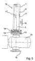
- Fig. 5 shows a fitting connection.
- Line 12 is on flange 14 by means of flange 18 flanged.
- the inliner 3 carries a flange 19, between the flange 13 of the valve 14 and the flange 18 of the tube 1 is clamped. That in Inliner 3 transported sour gas is over the Port 15 discharged from the fitting 14.
- On the outside Tube 1 is a connection 16 for loading the Washroom 4 provided.
- the gas flow in the inliner and in Wash cabinet 4 is in opposite directions, as indicated by arrows 17, 17 '. On this way, for example in the inliner 3 sour gas from a drilling site of a central drying plant be fed while with opposite Flow direction in the wash cabinet 4 heating gas one Heat source is fed to the drilling site.
- the Feeding process is done with standard winches and Steel cables carried out.
- the steel cable comes with threaded a leading auxiliary rope.
- the Auxiliary rope can, for example, in the course of Camera inspection.
- the pull rope can also be pulled through the Inliner strand flogged and at its backward End anchored.
- the inliner is then called Thrust unit threaded.
- the pull-in process can be carried out using Lubricants are significantly simplified. In curved sections of the original Pressure tube that are left in the line lubrication is essential. As a lubricant all commercially available lubricants up to Soft soap are used. As special suitable lubricant has proven to be bentonite. Bentonite is cheap and can be used Execution of work with water without problems be washed out. Will the entire washroom with Bentonite can be filled because of the corresponding Buoyancy can be prevented from being in gussets Fix leftovers. After pulling the liner in the straight or slightly curved Line sections are the strongly curved Sections as pre-made elements used. The liner pieces are connected via sleeves with right-left thread. At the end of the line the connection to the fittings is made via corresponding inliner passport pieces.
Landscapes
- Engineering & Computer Science (AREA)
- General Engineering & Computer Science (AREA)
- Mechanical Engineering (AREA)
- Pipeline Systems (AREA)
- Rigid Pipes And Flexible Pipes (AREA)
- Organic Low-Molecular-Weight Compounds And Preparation Thereof (AREA)
- Filling Or Discharging Of Gas Storage Vessels (AREA)
Description
- Fig. 1:
- eine Aufsicht auf die Leitung in einem Etagenbereich;
- Fig. 2:
- eine teilweise angeschnittene Darstellung des Inliners;
- Fig. 3:
- einen teilweise angeschnittenes vorgefertigtes Element für einen Horizontalbogen in Draufsicht;
- Fig. 4:
- einen Vertikalschnitt durch einen Abschnitt des in Fig. 2 gezeigten vorgefertigten Elements; und
- Fig. 5:
- einen Armaturenanschluß.
| Dimensionierung von Aramid-bewehrten Kunststoffrohren, Temperaturbereich -30 °C - +30 °C | ||
| Außendurchmesser | Wandstärke | Druckfestigkeit |
| (mm) | (mm) | (bar) |
| 143 | 16,5 | 80 |
| 179 | 17,5 | 100 |
| 273 | 21,5 | 80 |
- 1
- äußeres Rohr
- 2
- gekrummter Abschnitt
- 3
- Inliner
- 4
- Spülraum
- 5
- PEHD-Rohr
- 6
- Bewehrung
- 7
- Hülle
- 8
- Flansch
- 9
- Radius
- 10
- Hulse
- 11
- Deckel
- 12
- Leitung
- 13
- Flansch
- 14
- Armatur
- 15
- Anschluß
- 16
- Anschluß
- 17
- Gasfluß
- 18
- Rohrflansch
- 19
- Inlinerflansch
Claims (4)
- Verfahren zum Transport von Sauergas, dadurch gekennzeichnet, daß das Sauergas in ungetrocknetem Zustand transportiert wird, daß der Transport durch eine doppelwandige Leitung erfolgt, die aus einem äußeren Rohr (1) und einem gegen aggressive Medien resistenten Inliner (3) aufgebaut ist, wobei das Sauergas durch den Inliner (3) geleitet wird und ein zwischen dem äußeren Rohr (1) und dem Inliner (3) gebildeter Spülraum (4) von einem Spülmedium, insbesondere Gas, durchspült wird.
- Verfahren nach Anspruch 1, dadurch gekennzeichnet, daß der Spülraum (4) zum Transport von Nutzmedien, beispielsweise Heizgas oder Spindelöl, als Spülmedium verwendet wird.
- Verfahren nach Anspruch 1 oder 2, dadurch gekennzeichnet, daß der Druck im Inliner (3) auf 40 - 160 bar und im Spülraum (4) auf 10-40 bar eingestellt wird.
- Verfahren nach Anspruch 1, 2 oder 3, dadurch gekennzeichnet, daß der Spülraum (4) mit einem Drucksensor überwacht wird.
Applications Claiming Priority (3)
| Application Number | Priority Date | Filing Date | Title |
|---|---|---|---|
| DE19709373A DE19709373A1 (de) | 1997-03-07 | 1997-03-07 | Leitung für gefährdende Fluide und Verfahren zu deren Herstellung |
| DE19709373 | 1997-03-07 | ||
| PCT/EP1997/005563 WO1998040657A1 (de) | 1997-03-07 | 1997-10-09 | Leitung für gefährdende fluide und verfahren zu deren herstellung |
Publications (3)
| Publication Number | Publication Date |
|---|---|
| EP0990101A1 EP0990101A1 (de) | 2000-04-05 |
| EP0990101B1 true EP0990101B1 (de) | 2003-04-16 |
| EP0990101B2 EP0990101B2 (de) | 2009-08-26 |
Family
ID=7822566
Family Applications (1)
| Application Number | Title | Priority Date | Filing Date |
|---|---|---|---|
| EP97912156A Expired - Lifetime EP0990101B2 (de) | 1997-03-07 | 1997-10-09 | Verfahren zum transport von sauergas |
Country Status (5)
| Country | Link |
|---|---|
| EP (1) | EP0990101B2 (de) |
| AT (1) | ATE237777T1 (de) |
| DE (2) | DE19709373A1 (de) |
| DK (1) | DK0990101T3 (de) |
| WO (1) | WO1998040657A1 (de) |
Cited By (1)
| Publication number | Priority date | Publication date | Assignee | Title |
|---|---|---|---|---|
| GB2535474A (en) * | 2015-02-16 | 2016-08-24 | Acergy France SAS | Subsea pipe-in-pipe structures |
Families Citing this family (6)
| Publication number | Priority date | Publication date | Assignee | Title |
|---|---|---|---|---|
| US7122344B2 (en) | 1997-05-28 | 2006-10-17 | Claragen, Inc. | Methods for the production of purified recombinant human uteroglobin for the treatment of inflammatory and fibrotic conditions |
| US20060281681A1 (en) | 1997-05-28 | 2006-12-14 | Pilon Aprile L | Methods and compositions for the reduction of neutrophil influx and for the treatment of bronchpulmonary dysplasia, respiratory distress syndrome, chronic lung disease, pulmonary fibrosis, asthma and chronic obstructive pulmonary disease |
| DE69907708D1 (de) | 1998-09-24 | 2003-06-12 | Nkt Flexibles As Brondby | Verstärktes flexibles rohr mit leckflüssigkeitsrückführung |
| DE20219690U1 (de) * | 2002-12-19 | 2004-04-29 | Exxonmobil Production Deutschland Gmbh | Vorrichtung zum Transport von mehrphasigen Fluiden |
| WO2011026801A1 (en) | 2009-09-01 | 2011-03-10 | Shell Internationale Research Maatschappij B.V. | Method of protecting a flexible pipe from corrosion and a flexible pipe |
| US10513896B2 (en) | 2014-11-13 | 2019-12-24 | National Oilwell Varco Denmark I/S | Method of installing an unbonded flexible pipe |
Family Cites Families (10)
| Publication number | Priority date | Publication date | Assignee | Title |
|---|---|---|---|---|
| US2475635A (en) † | 1945-01-08 | 1949-07-12 | Elmer C Parsons | Multiple conduit |
| DE1173856B (de) † | 1963-02-12 | 1964-07-16 | Wintershall Ag | Verfahren zur Vermeidung von Schwefel-abscheidungen aus Erdgas in Steigrohren von Gasbohrungen |
| US3581775A (en) * | 1969-03-28 | 1971-06-01 | Flex Weld Inc | Flexible conduit for use with basic oxygen furnaces |
| US3777502A (en) * | 1971-03-12 | 1973-12-11 | Newport News Shipbuilding Dry | Method of transporting liquid and gas |
| DE3818998C3 (de) * | 1988-06-03 | 2003-02-27 | Tracto Technik | Verfahren zum Verlegen von Versorgungsleitungen |
| WO1990000698A1 (en) * | 1988-07-08 | 1990-01-25 | Rib Loc Group Limited | Means for and method of detecting and controlling pipeline leakages |
| US4886305A (en) * | 1988-08-12 | 1989-12-12 | Fibercast Company | Double containment pipe fittings and apparatus to adhesively install the same |
| CH677014A5 (de) * | 1988-10-25 | 1991-03-28 | Fischer Ag Georg | |
| DE3929325A1 (de) * | 1989-09-04 | 1991-03-07 | Wirsbo Pex Gmbh | Doppelwandiges leitungsrohr |
| FR2657416B1 (fr) † | 1990-01-23 | 1994-02-11 | Institut Francais Petrole | Procede et dispositif pour le transport et le traitement d'un gaz naturel. |
-
1997
- 1997-03-07 DE DE19709373A patent/DE19709373A1/de not_active Withdrawn
- 1997-10-09 DE DE59709877T patent/DE59709877D1/de not_active Expired - Lifetime
- 1997-10-09 AT AT97912156T patent/ATE237777T1/de not_active IP Right Cessation
- 1997-10-09 DK DK97912156T patent/DK0990101T3/da active
- 1997-10-09 EP EP97912156A patent/EP0990101B2/de not_active Expired - Lifetime
- 1997-10-09 WO PCT/EP1997/005563 patent/WO1998040657A1/de not_active Ceased
Cited By (2)
| Publication number | Priority date | Publication date | Assignee | Title |
|---|---|---|---|---|
| GB2535474A (en) * | 2015-02-16 | 2016-08-24 | Acergy France SAS | Subsea pipe-in-pipe structures |
| GB2535474B (en) * | 2015-02-16 | 2018-05-16 | Acergy France SAS | Subsea pipe-in-pipe structures |
Also Published As
| Publication number | Publication date |
|---|---|
| DK0990101T3 (da) | 2003-07-07 |
| DE19709373A1 (de) | 1998-09-10 |
| DE59709877D1 (de) | 2003-05-22 |
| EP0990101B2 (de) | 2009-08-26 |
| EP0990101A1 (de) | 2000-04-05 |
| ATE237777T1 (de) | 2003-05-15 |
| WO1998040657A1 (de) | 1998-09-17 |
Similar Documents
| Publication | Publication Date | Title |
|---|---|---|
| DE3140928C2 (de) | Vorrichtung für das nachträgliche Einziehen von Fernmeldekabeln | |
| DE69925045T2 (de) | Mit vinylharzen imprägniertes filz enthaltendes futter für ein mannloch | |
| DE69516085T2 (de) | Installation von rohren | |
| EP0315796A1 (de) | Doppelwandiges Rohrleitungssystem | |
| DE69517426T2 (de) | Verfahren zum auskleiden einer leitung mit einer auskleidung aus polymerem material | |
| EP0990101B2 (de) | Verfahren zum transport von sauergas | |
| DE2418797A1 (de) | Universalrohr und fittings dazu | |
| DE3841064A1 (de) | Rohr zum zwecke der rohrauskleidung | |
| DE102014109799A1 (de) | Rohrkupplung | |
| EP2025986B1 (de) | Rohreinheit umfassend mindestens zwei Rohre | |
| EP2210985B1 (de) | Anschlussvorrichtung | |
| DE202004014113U1 (de) | Beton-Fundierungselement eines Bauwerks | |
| DE202008013039U1 (de) | Medienverteilerrohr für eine Chlorelektrolyse-Anlage | |
| EP1322888B1 (de) | Rohrartige leitung oder behälter zum transport bzw. zum aufbewahren kryogener medien und verfahren zur herstellung | |
| CH700731B1 (de) | Formstück. | |
| CH696940A5 (de) | Kombinationsrohr. | |
| DE4134899C1 (en) | Flexible safety pipe for fluid media - comprises plastic core with plastic mantle and intermediate spiral chamber, with inner spiral corrugated plastic tube | |
| AT524848B1 (de) | Wasserversorgungssystem für ein Schienenfahrzeug | |
| AT304203B (de) | Doppelschalenrohrleitung | |
| DE19851162A1 (de) | Längskraftschlüssige Steckmuffe | |
| DE202011110778U1 (de) | Leitungszweigstück für Fallleitungen | |
| DE102017106301A1 (de) | Auslaufarmatur | |
| DE3106160A1 (de) | Rohrpassstueck | |
| DE60012224T2 (de) | Verteilervorrichtung in einem belüftungssystem | |
| DE4243460C1 (de) | Gasrohrsanierungsanordnung |
Legal Events
| Date | Code | Title | Description |
|---|---|---|---|
| PUAI | Public reference made under article 153(3) epc to a published international application that has entered the european phase |
Free format text: ORIGINAL CODE: 0009012 |
|
| 17P | Request for examination filed |
Effective date: 19990914 |
|
| AK | Designated contracting states |
Kind code of ref document: A1 Designated state(s): AT BE CH DE DK ES FR GB IT LI NL PT |
|
| RBV | Designated contracting states (corrected) |
Designated state(s): AT BE CH DE DK ES FR GB IT LI NL PT |
|
| RAP1 | Party data changed (applicant data changed or rights of an application transferred) |
Owner name: VEENKER, MANFRED, DR.-ING. |
|
| RIN1 | Information on inventor provided before grant (corrected) |
Inventor name: VEENKER, MANFRED, DR.-ING. |
|
| RAP1 | Party data changed (applicant data changed or rights of an application transferred) |
Owner name: BEB ERDGAS UND ERDOEL GMBH Owner name: VEENKER, MANFRED, DR.-ING. |
|
| RIN1 | Information on inventor provided before grant (corrected) |
Inventor name: SCHLEMM, FRIEDRICH Inventor name: VEENKER, MANFRED, DR.-ING. |
|
| 17Q | First examination report despatched |
Effective date: 20011010 |
|
| GRAG | Despatch of communication of intention to grant |
Free format text: ORIGINAL CODE: EPIDOS AGRA |
|
| RTI1 | Title (correction) |
Free format text: METHOD OF TRANSPORTING ACID GAS |
|
| GRAG | Despatch of communication of intention to grant |
Free format text: ORIGINAL CODE: EPIDOS AGRA |
|
| GRAH | Despatch of communication of intention to grant a patent |
Free format text: ORIGINAL CODE: EPIDOS IGRA |
|
| GRAH | Despatch of communication of intention to grant a patent |
Free format text: ORIGINAL CODE: EPIDOS IGRA |
|
| GRAA | (expected) grant |
Free format text: ORIGINAL CODE: 0009210 |
|
| AK | Designated contracting states |
Designated state(s): AT BE CH DE DK ES FR GB IT LI NL PT |
|
| PG25 | Lapsed in a contracting state [announced via postgrant information from national office to epo] |
Ref country code: IT Free format text: LAPSE BECAUSE OF FAILURE TO SUBMIT A TRANSLATION OF THE DESCRIPTION OR TO PAY THE FEE WITHIN THE PRESCRIBED TIME-LIMIT;WARNING: LAPSES OF ITALIAN PATENTS WITH EFFECTIVE DATE BEFORE 2007 MAY HAVE OCCURRED AT ANY TIME BEFORE 2007. THE CORRECT EFFECTIVE DATE MAY BE DIFFERENT FROM THE ONE RECORDED. Effective date: 20030416 |
|
| REG | Reference to a national code |
Ref country code: GB Ref legal event code: FG4D Free format text: NOT ENGLISH |
|
| REG | Reference to a national code |
Ref country code: CH Ref legal event code: EP |
|
| REF | Corresponds to: |
Ref document number: 59709877 Country of ref document: DE Date of ref document: 20030522 Kind code of ref document: P |
|
| GBT | Gb: translation of ep patent filed (gb section 77(6)(a)/1977) | ||
| REG | Reference to a national code |
Ref country code: DK Ref legal event code: T3 |
|
| PG25 | Lapsed in a contracting state [announced via postgrant information from national office to epo] |
Ref country code: PT Free format text: LAPSE BECAUSE OF FAILURE TO SUBMIT A TRANSLATION OF THE DESCRIPTION OR TO PAY THE FEE WITHIN THE PRESCRIBED TIME-LIMIT Effective date: 20030716 |
|
| PG25 | Lapsed in a contracting state [announced via postgrant information from national office to epo] |
Ref country code: GB Free format text: LAPSE BECAUSE OF NON-PAYMENT OF DUE FEES Effective date: 20031009 Ref country code: AT Free format text: LAPSE BECAUSE OF NON-PAYMENT OF DUE FEES Effective date: 20031009 |
|
| PG25 | Lapsed in a contracting state [announced via postgrant information from national office to epo] |
Ref country code: ES Free format text: LAPSE BECAUSE OF FAILURE TO SUBMIT A TRANSLATION OF THE DESCRIPTION OR TO PAY THE FEE WITHIN THE PRESCRIBED TIME-LIMIT Effective date: 20031030 |
|
| PG25 | Lapsed in a contracting state [announced via postgrant information from national office to epo] |
Ref country code: LI Free format text: LAPSE BECAUSE OF NON-PAYMENT OF DUE FEES Effective date: 20031031 Ref country code: DK Free format text: LAPSE BECAUSE OF NON-PAYMENT OF DUE FEES Effective date: 20031031 Ref country code: CH Free format text: LAPSE BECAUSE OF NON-PAYMENT OF DUE FEES Effective date: 20031031 Ref country code: BE Free format text: LAPSE BECAUSE OF NON-PAYMENT OF DUE FEES Effective date: 20031031 |
|
| ET | Fr: translation filed | ||
| PLBQ | Unpublished change to opponent data |
Free format text: ORIGINAL CODE: EPIDOS OPPO |
|
| PLBI | Opposition filed |
Free format text: ORIGINAL CODE: 0009260 |
|
| PLAX | Notice of opposition and request to file observation + time limit sent |
Free format text: ORIGINAL CODE: EPIDOSNOBS2 |
|
| 26 | Opposition filed |
Opponent name: EXXONMOBIL PRODUCTION DEUTSCHLAND GMBH Effective date: 20040116 |
|
| BERE | Be: lapsed |
Owner name: *BEB ERDGAS UND ERDOL G.M.B.H. Effective date: 20031031 Owner name: *VEENKER MANFRED Effective date: 20031031 |
|
| NLR1 | Nl: opposition has been filed with the epo |
Opponent name: EXXONMOBIL PRODUCTION DEUTSCHLAND GMBH |
|
| GBPC | Gb: european patent ceased through non-payment of renewal fee |
Effective date: 20031009 |
|
| REG | Reference to a national code |
Ref country code: DK Ref legal event code: EBP |
|
| REG | Reference to a national code |
Ref country code: CH Ref legal event code: PL |
|
| PLAX | Notice of opposition and request to file observation + time limit sent |
Free format text: ORIGINAL CODE: EPIDOSNOBS2 |
|
| PLBB | Reply of patent proprietor to notice(s) of opposition received |
Free format text: ORIGINAL CODE: EPIDOSNOBS3 |
|
| PLCK | Communication despatched that opposition was rejected |
Free format text: ORIGINAL CODE: EPIDOSNREJ1 |
|
| APBP | Date of receipt of notice of appeal recorded |
Free format text: ORIGINAL CODE: EPIDOSNNOA2O |
|
| APAH | Appeal reference modified |
Free format text: ORIGINAL CODE: EPIDOSCREFNO |
|
| APBQ | Date of receipt of statement of grounds of appeal recorded |
Free format text: ORIGINAL CODE: EPIDOSNNOA3O |
|
| APAH | Appeal reference modified |
Free format text: ORIGINAL CODE: EPIDOSCREFNO |
|
| APBU | Appeal procedure closed |
Free format text: ORIGINAL CODE: EPIDOSNNOA9O |
|
| PUAH | Patent maintained in amended form |
Free format text: ORIGINAL CODE: 0009272 |
|
| STAA | Information on the status of an ep patent application or granted ep patent |
Free format text: STATUS: PATENT MAINTAINED AS AMENDED |
|
| 27A | Patent maintained in amended form |
Effective date: 20090826 |
|
| AK | Designated contracting states |
Kind code of ref document: B2 Designated state(s): AT BE CH DE DK ES FR GB IT LI NL PT |
|
| REG | Reference to a national code |
Ref country code: ES Ref legal event code: FD2A Effective date: 20031010 |
|
| NLR2 | Nl: decision of opposition |
Effective date: 20090826 |
|
| NLR3 | Nl: receipt of modified translations in the netherlands language after an opposition procedure | ||
| PGFP | Annual fee paid to national office [announced via postgrant information from national office to epo] |
Ref country code: FR Payment date: 20111110 Year of fee payment: 15 Ref country code: NL Payment date: 20111025 Year of fee payment: 15 |
|
| REG | Reference to a national code |
Ref country code: NL Ref legal event code: V1 Effective date: 20130501 |
|
| REG | Reference to a national code |
Ref country code: FR Ref legal event code: ST Effective date: 20130628 |
|
| PG25 | Lapsed in a contracting state [announced via postgrant information from national office to epo] |
Ref country code: NL Free format text: LAPSE BECAUSE OF NON-PAYMENT OF DUE FEES Effective date: 20130501 Ref country code: FR Free format text: LAPSE BECAUSE OF NON-PAYMENT OF DUE FEES Effective date: 20121031 |
|
| PGFP | Annual fee paid to national office [announced via postgrant information from national office to epo] |
Ref country code: DE Payment date: 20131219 Year of fee payment: 17 |
|
| REG | Reference to a national code |
Ref country code: DE Ref legal event code: R119 Ref document number: 59709877 Country of ref document: DE |
|
| PG25 | Lapsed in a contracting state [announced via postgrant information from national office to epo] |
Ref country code: DE Free format text: LAPSE BECAUSE OF NON-PAYMENT OF DUE FEES Effective date: 20150501 |