EP0990295B1 - Procede de bobinage et bobines pour machine electrique tournantes - Google Patents
Procede de bobinage et bobines pour machine electrique tournantes Download PDFInfo
- Publication number
- EP0990295B1 EP0990295B1 EP98932245A EP98932245A EP0990295B1 EP 0990295 B1 EP0990295 B1 EP 0990295B1 EP 98932245 A EP98932245 A EP 98932245A EP 98932245 A EP98932245 A EP 98932245A EP 0990295 B1 EP0990295 B1 EP 0990295B1
- Authority
- EP
- European Patent Office
- Prior art keywords
- coils
- winding
- coil
- bundles
- accordance
- Prior art date
- Legal status (The legal status is an assumption and is not a legal conclusion. Google has not performed a legal analysis and makes no representation as to the accuracy of the status listed.)
- Expired - Lifetime
Links
Images


Classifications
-
- H—ELECTRICITY
- H02—GENERATION; CONVERSION OR DISTRIBUTION OF ELECTRIC POWER
- H02K—DYNAMO-ELECTRIC MACHINES
- H02K3/00—Details of windings
- H02K3/04—Windings characterised by the conductor shape, form or construction, e.g. with bar conductors
- H02K3/12—Windings characterised by the conductor shape, form or construction, e.g. with bar conductors arranged in slots
-
- H—ELECTRICITY
- H02—GENERATION; CONVERSION OR DISTRIBUTION OF ELECTRIC POWER
- H02K—DYNAMO-ELECTRIC MACHINES
- H02K3/00—Details of windings
- H02K3/04—Windings characterised by the conductor shape, form or construction, e.g. with bar conductors
- H02K3/28—Layout of windings or of connections between windings
Definitions
- the invention relates to the field of machines rotating electrics, which have at least two coaxial armatures, separated by an air gap: a stator fixed and a rotor animated with a uniform movement.
- These frames can be cylindrical and the machine creates then a radial field.
- the conductors are placed in notches distributed on the internal periphery of the stator or the outer periphery of the rotor.
- the drivers are parallel to the axis of rotation of the machine.
- These reinforcements can also take the form of discs and in this case, the machine creates an axial field.
- the conductors are placed in radial notches they are therefore perpendicular to the axis of rotation of the machine.
- the conductors are arranged in the slots of a magnetic circuit, according to different types of windings, chosen according to the applications.
- the windings are made from coils or bars, but here we're mainly interested in windings made with coils.
- the coils are made from insulated conductors between them and which are wound according to turns concentric. Each coil is placed in two notches different from the magnetic circuit. We generally call bundles, the two parts of the coil located in the notches and involute or coil head, the part of the coil which is outside the magnetic circuit.
- Conventional windings are concentric coils and entangled coils, especially coils of the type nested which are used for average machines and strong powers.
- Windings with concentric coils can be produced by alternating pole or consequent pole winding.
- the conductors are placed in a single notch plane which is composed of two layers made successively, for a winding with consequent poles and as many layers as phase, for alternating pole winding.
- Windings in one plane are today essentially intended for low power machines for which manufacturing costs are preponderant before technical performance.
- the conductors are in round wires with a notch filling less than that can be obtained with flat conductors and the no winding is complete, to the detriment of the appearance of the rotating field.
- Coils with entangled coils of the nested type allow shortened steps and therefore allow the elimination of certain electrical harmonics.
- the conductors are arranged in the notches in two different planes, separated by insulators.
- a coil is produced by winding flat conductors previously isolated in a lathe wind, so as to obtain one or more turns concentric.
- the coil generally has the shape of a shuttle which is then stretched to open the spool and raise the head coil.
- the gap between the two long sides of a coil intended for be placed in notches in the magnetic circuit is depending on the number of poles. To the extent that both long sides of the spool are in staggered planes one compared to each other, these two sides will also be located in different planes, when the coil is placed in the magnetic circuit. This allows to realize the electrical circuit of the machine, by arranging the coils one after the other in the circuit magnetic.
- Nested type windings have many electrical advantages, due to the existence of two winding planes.
- the length and size of the coil heads are relatively large, which is detrimental to electrical performances and moreover, induces an additional cost of made from the amount of copper used.
- step lifting is a essentially manual operation, making it difficult any automation.
- the invention firstly relates to a coil for magnetic circuit of a rotating electrical machine, comprising two bundles and two coil heads of which the thickness is substantially equal to a fraction of the thickness of said bundles, said coil being symmetrical with respect to the median plane of the beams.
- the coil according to the invention comprises at least minus a head that is flared relative to the beams and has protruding parts.
- the maximum width of the projecting parts is advantageously less than the difference between two notches of the magnetic circuit at said head.
- the coil When the coil is intended for an armature machine discoid, it has a shape appreciably trapezoidal, the bundles and the coil heads being in the same plane.
- this coil has an outer surface plane.
- the coil heads have a thickness at most equal to half of the thickness of the beams.
- the invention also relates to a method of making of a winding for the magnetic circuit of a machine rotating electric, the process of placing in the notches in the magnetic circuit of the coils conforming to the invention, the coils being arranged so adjacent, in at least two winding layers successive and independent, so as to fulfill all the notches.
- the method consists in forming the coils directly in the notches of the magnetic circuit.
- the method according to the invention consists in winding according to at least one notch plane, each notch plane being produced with at least two layers of coils, the heads of said coils being superimposed and nested one inside the other, partially overlapping.
- the coils are placed successively in each plane notch and the bundles of the same coil are located in the same notch plane.
- the nesting of the coil heads is obtained by reversing the position of the coils of a winding layer to the other.
- the process is implemented with concentric coils.
- the invention relates to a winding produced with coils according to the invention, a first group of coils being placed only in the "bottom notch” plane and a second group of coils being placed only in the "high” plane notch ", the two planes being independent.
- Coils used in nested type windings are usually obtained from shuttles which are stretched.
- FIG. 1 showing such a coil 1, placed in the magnetic circuit 2 of the stator of a machine rotating with cylindrical frames.
- Reference 3 designates the bore of the stator in which is placed the rotor (not shown in Figure 1).
- the notches are closed with closing wedges notch (not shown in Figure 1) which are placed in the recesses 6, 7 in dovetail.
- the two long sides 8 and 9 of the coil 1 are in staggered shots.
- the beam 8 is placed in the bottom plane notch "4 and the beam 9 is placed in the plane" high notch "5.
- the "top notch” plane is located on closer to the air gap, while the lower plane notch “is the plane farthest from the air gap.
- the coil head has the reference 10.
- References 11 and 12 denote the electrical connections with other coils.
- Figure 2 shows that with a nested type winding, the length of the coil head is relatively large.
- the involute is all the longer as the number of poles is small.
- the involute did not of utility from an electrical point of view. It is therefore the builder's interest in reducing it to reduce the amount of copper used, while improving electrical performance for the machine.
- the involute is also very bulky. This requires that the carcass of the rotating machine.
- the size of the involute is particularly detrimental to discoid machines.
- the notches in the magnetic circuit of a discoid armature are distributed along radii of the reinforcement. They lead to the periphery and to a bore central armature, smaller diameter.
- the length of the coil heads requires increasing the diameter of this central bore. This forces to increase not only the dimensions of the machine casing, but also the dimensions of the magnetic circuit and those conductors and therefore the volume of copper.
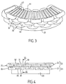
- FIGS 3 and 4 illustrate a winding of a discoid machine frame, in steps of 1 with 4 and two winding planes, realized with the coils according to the invention.
- Winding in two planes (“top notch” and “bottom notch ”) is conventionally used because it allows to obtain a progressive rotating field.
- the coil according to the invention could also be used to wind in a single plane. It would lead to the same advantages which are to reduce the size of the involute and therefore of the machine.
- Reference 20 designates the magnetic circuit of the armature and the reference 40 the notches of the magnetic circuit.
- the notches are distributed along radii of the frame discoid.
- the winding is carried out according to two planes 22 and 23 commonly known as “top notch” and “bottom notch”.
- the winding comprises two layers conductors 24, 25 and 26, 27, so as to fill all the notches.
- the conductor layers are shaped annular. They are flat and parallel to each other.
- the gap between the two bundles of the same coil 30 corresponds to the one that exists between four notches, the winding illustrated being of the step type from 1 to 4.
- the bundles of the coils are generally maintained by notch shims which are not shown in the figures.
- the distance between the bundles of a coil according to the invention therefore depends on the winding pitch selected for the machine.
- a coil according to the invention is therefore flat and general trapezoidal shape.
- FIGs 3 and 4 already show that the winding is made with coils 30 which are identical and which therefore have an identical volume and shape.
- Figure 5 is a partial top view of the machine illustrated in Figures 3 and 4, which shows the coil 31 in the upper layer 24 of the "top notch" plane 22 and the coils 32 and 33 in the lower layer 25 of this same plan 22.
- plan 22 which is identical to that of plan 23.
- the coils 32 and 33 have two beams 34 and 35 adjacent.
- coils 30 are also arranged adjacent to each other so that fill the notches left free by the coils of the lower layer 25.
- the bundles 36 and 37 of the coil 31 are placed in the slots not occupied by the coils 32 and 33.
- the coils 30 are arranged so that the heads of the coils located respectively in the layer lower 25 and in the upper layer 24 are superimposed.
- the head 51 of the coil 31 and the heads coils 32 and 33 are superimposed overlapping partially, as shown in Figure 5.
- the winding according to the invention When the winding according to the invention is carried out according to two planes, it thus comprises two groups of coils, the first group being placed only in the bottom plane notch "while the second group is arranged only in the "top notch" plane. These two plans are therefore independent of each other and carried out successively.
- FIG. 5 shows that the coil 31 is symmetrical by relation to the median plane of the beams 36, 37 materialized by line VI-VI. This median plane passes through the middle of each of the coil heads 51 and 52 and it's perpendicular to the plane passing through the two beams 36 and 37.
- the coil heads are flared according to a diameter of the machine. So the reel head 51 of reel 31 has two parts in projection, referenced 41 and 42.
- the flaring of the heads of coil mainly results from the manufacturing process which has been retained and does not constitute a characteristic essential of the coil.
- the protruding parts are however not of any dimensions. Their width should counted from the corresponding beam either in all point less than half the distance between two notches of the magnetic circuit, at the level of the head 51. This allows not to create extra thicknesses between two coils of a same layer, for example coils 32 and 33 with their projecting parts 45 and 46.
- the reference L designates the maximum width of the part in projection 42 of the coil 31.
- Figure 6 is a view in section of Figure 5, along the median plane VI-VI. This figure shows the coils in the two notch planes 22 and 23. These two planes are conventionally separated by a insulation which is not illustrated in figure 6.
- the head 51 placed on the diameter outside of the frame like the head 52 placed on the inside diameter of the frame, have a thickness in a plane transverse to the beams which is substantially half the thickness of the beams 36 or 37 in the notches, the latter corresponding substantially to the height of the notch plane 22.
- the coil 31 has an outer surface 60 which is substantially planar.
- the thickness of the coil head is not halved over its entire length.
- Figure 6 shows besides that over a length 1, the thickness of the coil 31 decreases continuously until the thickness is reduced desired.
- the section of the coil 31 being identical at the level of the bundles 36, 37 and coil heads 51, 52, the coil conductors are therefore spread out and distributed in the heads, so as to reduce the thickness of the coil. Therefore, the coil may have protuberances like those referenced 41 and 42 or 45 and 46. These protrusions also reduce the length coil heads.
- the coils are inverted from one layer of the winding to the other.
- the covering of the coil located in different layers of the same plane notch is partial.
- the two coils 31 and 32 having, at their heads, a thickness reduced substantially by half by compared to that of their beams, the thickness of the heads of the two coils also corresponds substantially to that the corresponding notch plane 22.
- Figure 6 also illustrates the coils 38 and 39 placed in the notch plane 23 (bottom of the notch). They present the same shape as the coil 31 and are also in inverted position relative to each other, which allows the nesting of their coil heads on the one hand, 55 and 57 and on the other hand, 56 and 58.
- FIG. 7 is a view partial sectional view of Figure 5, along VII-VII.
- the figure 7 shows only the coils present in the plane 22 (top of notch).
- the coils of each plane 22 and 23 are symmetrical with respect to plane 61 which is the median plane between the two notch planes 22 and 23, with an offset related to the characteristics of the machine.
- FIG. 7 confirms that the coil heads 51, respectively 52 of the coil 31 are well fitted in the coil heads 53, respectively 54 of the coil 32.
- figure 8 is a view partial sectional view of Figure 5, along VIII-VIII, on which only the coils present in the plane 22 are represented.
- the coils can cross without creating excess thickness.
- the coils according to the invention include, for this purpose, turns of different lengths.
- the involute length is reduced thanks to the use of coils whose bundles are placed in the same notch plane and whose heads can fit.
- the general form of involutes is very compact, both on the outside diameter and on the internal diameter of the armature.
- Figure 9 is a view partial plan view of the magnetic circuit of a machine discoid, equipped with a winding of the pitch type from 1 to 4.
- This magnetic circuit includes, for comparison, coils 30 as illustrated in FIGS. 3 to 8 and coils 130 of the nested type.
- the size of the winding produced with the coils 30 is reduced compared to that of the winding nested made with the coils 130, at the level of the developing, both on the outside diameter 131 of the magnetic circuit 132 only on the periphery of the bore central 133.
- This bore is intended to receive the shaft of the machine.
- the diameter of the central bore of the magnetic circuit as the diameter outside the magnetic circuit can be reduced.
- each plane winding (“top notch” and "bottom notch”) is made with two layers of coils, the two planes being independent.
- Machines with different characteristics can impose to realize, in a winding in two planes, each winding plane with three layers of coils. This example embodiment is not illustrated in the figures.
- the winding can be made with two different types of coil, having a substantially identical volume.
- the first type of coil is similar to that of the coil 31 illustrated in particular in FIGS. 5 to 8, the thickness of the corresponding coil heads approximately one third of the thickness of the beams of the coil, itself substantially equal to the height of the plane notch (about half the total height of the notch).
- a coil of this first type has a substantially flat outer surface.
- the second type of coil has coil heads whose thickness is substantially identical to that of coils of the first type, i.e. about a third of the thickness of the beams, but which are placed in the central part of the cross section of the beams.
- a coil of this second type therefore has no flat outer surface.
- the layer coil heads different from the same winding plane are nested and superimposed, partially overlapping.
- the thickness of the coil heads is substantially equal to a fraction of the thickness of bundles, this fraction depending on the number of layers necessary to form the winding in a notch plane.
- Figure 10 is a partial plan view of an armature of a discoid machine whose characteristics are different from the machine illustrated in figures 3 to 8.
- the winding pitch is from 1 to 8 and from 2 to 7. This makes it necessary to carry out the winding with reels concentric.
- Figure 10 illustrates only the coils located in the "bottom notch" shot.
- the winding incorporates coils concentric to obtain the desired winding pitch.
- the winding will be carried out from two coils concentric.
- Reference 70 designates the magnetic circuit of the machine discoid with radial notches.
- the coils 81, 82, 83 and 84 are located in the first layer of the plane "bottom notch", while the coils 85 and 86 are in the second layer of this same plane.
- the coils 81, 83 and 85 are identical, therefore have identical volume and shape and correspond to a first type of coil for which the gap between the two bundles is 7 notches.
- the coils 82, 84, and 86 are identical, therefore have identical volume and shape and correspond to a second type of coil for which the gap between the two bundles is 5 notches.
- the involutes of all these coils have a reduced thickness and substantially equal to half of the thickness of the beams.
- the first winding layer of the plane is produced "bottom of notch" by placing in the notches, so adjacent, coils of the first type, such as coils 81 and 83 whose beams 71 and 72 are located in adjacent notches, then arranging, inside these coils, coils of the second type, like the coils 82 and 84.
- the order in which the first and second coils type are placed in the notches is in practice indifferent.
- the second winding layer of the plane is then formed "bottom notch", placing similarly but in the notches left free, coils of the first and the second type, like coils 85 and 86.
- the bundles 73 and 75 of coils 85 and 86 are placed in adjacent notches, such as harnesses 74 and 76 of these same coils.
- the coils are reversed between the first and the second winding layer. Otherwise, the thickness of the coil heads 77 and 78 of the coil 85 and coil heads 79 and 80 of coil 86 is substantially equal to half the thickness of beams. It is the same for the other coils.
- the coil heads located in layers different from the same notch plane, are nested one in the other and superimposed by partially overlapping.
- the head 77 of the coil 85 partially covers the heads of the coils 81, 82, 83 and 84 located in the first winding layer of the "bottom notch" plane.
- the coils according to the invention again allow reduce the length of the coil heads since the bundles of the same coil belong to the same plane notch. Furthermore, the reduced thickness of the coil allows, in the same notch plane, to nest, which further reduces the length of the coil heads to give them a compact shape.
- each conductor plane is obtained by arranging the coils in the notches according to successive and independent layers, each layer being located in the same plane of the magnetic circuit.
- each of these two planes is formed of independently and successively, by arranging the coils appropriately.
- the turns of a coil are directly formed from copper wire drums in the notches in the magnetic circuit and the coil heads in courses are calibrated directly to the form desired by means of a removable tool.
- the coils are advantageously produced continuously, that is to say without breaking the wire.
- the circuits of each phase can be performed directly, by successively and continuously forming the coils of each of the circuits. This avoids everything electrical connection after the completion of coils.
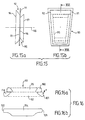
- FIG. 15 shows that the tool 90 comprises a support plan 91 of trapezoidal shape.
- a first part 92 On a face of the support 91, is fixed a first part 92 also trapezoidal in shape and whose section believes to continuously from its internal surface 93, fixed on the support, up to its external surface 94.
- the section of the internal surface 96, respectively the section of the external surface 97, is less than the section of the internal surface 93 of the first part 92, respectively to the section of the external surface 94 of this same part 92.
- the dimensions of the tool 90 depends of course on dimensions of the coil to be produced.
- the height of the room 92 and the height of the room 95 correspond substantially to the height of the bundle 104 of the coil illustrated in FIG. 16.
- the length of the tool 90 (according to section XVI-XVI) roughly corresponds to the average length of the coil.
- the width of room 95 (along a line perpendicular to the section plane XVI-XVI) corresponds substantially at the width of the step while the width of piece 92 corresponds to approximately the width of the step increased by 10%, in order to reduce the length of the coil.
- a coil according to the invention is obtained, in the way next.
- the tool 90 described in FIG. 15 is mounted on a lathe to be wound, the axis of which bears the reference 98. Des conductors are then wound on the tooling, the turns having different lengths due to the given shape in the first and second rooms 92 and 95.
- FIG 16a which is a sectional view according to XVI-XVI of tool 90 after winding conductors, two windings 100 and 101 are obtained conductors, the shape of which depends on that of the first and second parts 92 and 95.
- the next operation is to raise winding 101 at winding 100, according to the arrows F mentioned in FIG. 16a.
- FIG 16b is a side view along one of the bundles of the coil.
- the two coil heads 102 and 103 have a thickness which is substantially equal to half of the thickness of the beam 104.
- the tools illustrated in figure 15 are suitable for production of coils according to the invention, intended for magnetic circuit of discoid machines including a plane of winding is carried out in two successive layers of coils. It is made up of pieces of general shape trapezoidal, so as to allow the realization of coils which will also be trapezoidal for be able to be placed in radial slots in the circuit magnetic.
- the tools should therefore be modified for the realization coils for the magnetic circuit of machines cylindrical.
- the implementation method is unchanged.
- the coils for cylindrical machines differ slightly of those described above.
- the notches of the magnetic circuit of such machines are all parallel to the machine axis and, in the same notch plane, the spacing between two notches is constant at one end of the magnetic circuit to the other.
- the distance between the bundles of a coil is therefore also constant. This is not the case for a coil for a discoid machine, like coils 30 illustrated in FIG. 3.
- the gap between the two beams of the coil will be different, depending on whether the coil must be placed in the "low notch” plane or in the "high notch” plane notch ". This is apparent in particular from FIG. 1.
- the coils according to the invention intended for a cylindrical machine are not planar but form a portion of cylinder whose curvature depends on the diameter of the machine. This is why, winding in the same plane notch requires as many coil types as the plane includes layers of coils, since the coils do not cannot be inverted to nest with each other others.
- coils for armature machines cylindrical are symmetrical with respect to the median plane bundles of the coil.
- the projection in a plane passing through the two bundles of a coil according to the invention intended for a cylindrical machine has a general shape rectangular.
- the coils and the winding method according to the invention are advantageous for both underwired machines discoids and cylindrical frame machines.
- the coils allow, in fact, to reduce the length involutes, while the winding process can be easily automated, the coils being placed in notches of the magnetic circuit in layers successive and independent.
- the reduction in the length of the involutes leads to a decrease in the amount of copper used, compared to a machine whose winding is of the nested type, the machine characteristics being otherwise identical.
- a winding produced with coils according to the invention makes it possible to obtain a gain of the order 20% on the stator copper volume and therefore substantially the same gain for joule stator losses.
- the machine efficiency increased from 87.4% to 89.5%. It is therefore improved by 2.1%.
- reducing the length of the also helps retain the minimum sizing of a machine frame, without have to increase the diameter of the central bore by the frame for the passage of the involutes.
- the coils according to the invention allow to reduce the diameter of the reinforcements and therefore the dimensions of the magnetic circuit.
Landscapes
- Engineering & Computer Science (AREA)
- Power Engineering (AREA)
- Windings For Motors And Generators (AREA)
- Manufacture Of Motors, Generators (AREA)
- Insulation, Fastening Of Motor, Generator Windings (AREA)
Description
Claims (14)
- Bobinage pour circuit magnétique d'une machine électrique tournante comprenant des bobines (30) placées dans des encoches (40) du circuit magnétique (20, 70) et disposées de façon adjacente, selon au moins deux couches de bobines successives identiques et indépendantes, de façon à remplir toutes les encoches, chaque bobine comprenant deux faisceaux (36, 37 ; 73, 74 ; 75, 76) et deux têtes de bobines (51, 52 ; 77, 78 ; 79, 80) dont l'épaisseur est sensiblement égale à une fraction de l'épaisseur des faisceaux et étant symmétrique par rapport au plan médian des faisceaux, les faisceaux des bobines des deux couches étant placés dans un même plan d'encoche et les bobines successives et indépendantes étant disposées inversées l'une par rapport à l'autre pour permettre aux têtes de bobines des deux couches d'être emboítées l'une dans l'autre et superposées en se recouvrant partiellement.
- Bobinage selon la revendication 1, selon lequel un premier groupe de bobines (38, 39 ; 83, 84, 85, 86) est placé uniquement dans le plan "bas d'encoche" (23) et un deuxième groupe de bobines (31, 32) est placé uniquement dans le plan "haut d'encoche" (22).
- Bobinage selon la revendication 1 ou 2, selon lequel au moins une tête de bobine (51, 52) est évasée par rapport aux faisceaux (36, 37) et présente des parties en saillie (41, 42 ; 43, 44).
- Bobinage selon la revendication 3, selon lequel la largeur maximale des parties en saillie (41, 42 ; 43, 44) est inférieure à l'écart entre deux encoches (40) du circuit magnétique (20) au niveau de la tête (51, 52).
- Bobinage selon l'une des revendications précédentes, destiné à une machine à armatures discoïdes, chaque bobine présentant une forme trapézoidale.
- Bobinage selon la revendication 5, selon lequel chaque bobine présente une surface extérieure (60) plane.
- Bobinage selon l'une des revendications 1 à 4, destiné à une machine à armatures cylindriques, selon lequel la projection de chaque bobine dans un plan passant par ses faisceaux, est sensiblement rectangulaire, les faisceaux et les têtes de la bobine étant dans un même plan de cylindre, dont le rayon de courbure est identique à celui de la machine.
- Bobinage selon l'une des revendications précédentes, selon lequel les têtes présentent une épaisseur au plus égale à la moitié de l'épaisseur des faisceaux.
- Procédé de réalisation d'un bobinage pour le circuit magnétique d'une machine électrique tournante, à courant alternatif, multiphasée, et multipôle, le procédé consistant à placer dans les encoches (40) du circuit magnétique (20, 70) des bobines conformes à l'une des revendications 1 à 8, les bobines étant disposées, de façon adjacente, selon au moins deux couches de bobines identiques successives et indépendantes, de façon à remplir toutes les encoches, et consistant à réaliser chaque plan d'encoche avec au moins deux couches de bobines et à emboíter les têtes des bobines l'une dans l'autre en inversant la position des bobines (30) d'une couche de bobinage à l'autre, les têtes des bobines étant superposées en se recouvrant partiellement et les faisceaux des bobines des deux couches étant placés dans un même plan d'encoche.
- Procédé de réalisation d'un bobinage conforme à la revendication 9, consistant à former les bobines directement dans les encoches (40) du circuit magnétique (20, 70).
- Procédé de réalisation d'un bobinage conforme à la revendication 10, selon lequel les bobines de chaque circuit électrique d'une phase déterminée sont réalisées en continu.
- Procédé de réalisation d'un bobinage conforme à l'une des revendications 9 à 11 et selon deux plans d'encoche (22, 23), les bobines étant placées successivement dans chaque plan d'encoche et les faisceaux d'une même bobine étant situés dans le même plan d'encoche (22, 23).
- Procédé de réalisation d'un bobinage conforme à l'une des revendications 9 à 12 et au pas plus grand que 1 à 4, mis en oeuvre avec des bobines concentriques (81, 83, 85 ; 82, 84, 86).
- Procédé de réalisation d'un bobinage conforme à l'une des revendications 9 à 12, et au pas de 1 à 4 pour une machine discoíde, mis en oeuvre avec des bobines (30) identiques.
Priority Applications (1)
| Application Number | Priority Date | Filing Date | Title |
|---|---|---|---|
| DE69825895T DE69825895T3 (de) | 1997-06-20 | 1998-06-19 | Verfahren zum bewickeln und wicklungen für elektrische maschinen |
Applications Claiming Priority (3)
| Application Number | Priority Date | Filing Date | Title |
|---|---|---|---|
| FR9707731A FR2765041B1 (fr) | 1997-06-20 | 1997-06-20 | Procede de bobinage et bobines pour machine electrique tournante |
| FR9707731 | 1997-06-20 | ||
| PCT/FR1998/001297 WO1998059402A1 (fr) | 1997-06-20 | 1998-06-19 | Procede de bobinage et bobines pour machine electrique tournantes |
Publications (3)
| Publication Number | Publication Date |
|---|---|
| EP0990295A1 EP0990295A1 (fr) | 2000-04-05 |
| EP0990295B1 true EP0990295B1 (fr) | 2004-08-25 |
| EP0990295B2 EP0990295B2 (fr) | 2011-06-29 |
Family
ID=9508253
Family Applications (1)
| Application Number | Title | Priority Date | Filing Date |
|---|---|---|---|
| EP98932245A Expired - Lifetime EP0990295B2 (fr) | 1997-06-20 | 1998-06-19 | Procede de bobinage et bobines pour machine electrique tournantes |
Country Status (9)
| Country | Link |
|---|---|
| EP (1) | EP0990295B2 (fr) |
| JP (1) | JP4121040B2 (fr) |
| AT (1) | ATE274762T1 (fr) |
| CA (1) | CA2294106C (fr) |
| DE (1) | DE69825895T3 (fr) |
| DK (1) | DK0990295T4 (fr) |
| ES (1) | ES2227857T5 (fr) |
| FR (1) | FR2765041B1 (fr) |
| WO (1) | WO1998059402A1 (fr) |
Families Citing this family (2)
| Publication number | Priority date | Publication date | Assignee | Title |
|---|---|---|---|---|
| FR2838883B1 (fr) * | 2002-02-28 | 2004-08-13 | Valeo Equip Electr Moteur | Elements conducteurs pour un stator d'une machine electrique tournante et machine electrique tournante pourvue de tels elements conducteurs |
| JP2021175230A (ja) * | 2020-04-21 | 2021-11-01 | 愛三工業株式会社 | 回転電機 |
Family Cites Families (16)
| Publication number | Priority date | Publication date | Assignee | Title |
|---|---|---|---|---|
| DE558486C (de) † | 1928-12-22 | 1932-09-07 | Siemens Schuckertwerke Akt Ges | Stabwicklung fuer elektrische Kommutatormaschinen |
| US2683232A (en) * | 1949-09-21 | 1954-07-06 | Siemens Ag | Winding assembly for disk-type electric motors or generators |
| DE1613561A1 (de) † | 1967-02-14 | 1970-04-23 | Bbc Brown Boveri & Cie | Verfahren zur Herstellung von Kaefigwicklungen fuer Induktionsmotoren |
| GB1323062A (en) * | 1969-07-16 | 1973-07-11 | Parsons Co Ltd C A | Dynamo-electric machines |
| JPS5610053A (en) * | 1979-07-05 | 1981-02-02 | Matsushita Electric Ind Co Ltd | Method for inserting coil winding of armature stator |
| AU7444581A (en) * | 1980-08-25 | 1982-03-04 | Card-O-Matic Pty. Limited | Electric machine |
| US5231324A (en) * | 1990-07-19 | 1993-07-27 | Kabushiki Kaisha Toshiba | Three-phase armature winding |
| DE4125044A1 (de) * | 1991-07-29 | 1993-02-04 | Wolfgang Hill | Als scheibenlaeufer ausgebildeter elektromotor mit radial zur rotationsachse angeordnetem rotor und blechpaket |
| DE4209532C1 (de) * | 1992-03-24 | 1993-06-24 | Ruoss G Spezialmaschinen Elektroind | Verfahren zum direkten Bewickeln eines Ankers und Ankerwickelmaschine hierfür |
| DE9212889U1 (de) † | 1992-09-24 | 1994-01-27 | Siemens AG, 80333 München | Wicklungsanordnung für eine mehrphasige elektrische Maschine |
| JPH06209535A (ja) * | 1993-01-07 | 1994-07-26 | Toyota Motor Corp | モータのコイル構造 |
| DE4302807C2 (de) † | 1993-02-02 | 1995-03-23 | Wolfgang Hill | Mehrphasige elektrische Maschine und Verfahren zu ihrer Herstellung |
| DE4403302A1 (de) † | 1994-02-03 | 1995-08-10 | Licentia Gmbh | Elektrische Maschine, insbesondere ein bürstenloser Gleichstrommotor |
| DE4411749C2 (de) † | 1994-04-06 | 1996-08-29 | Wolfgang Hill | Mehrphasige elektrische Maschine mit zusammengefügten Leitersträngen |
| JPH08223840A (ja) † | 1995-02-17 | 1996-08-30 | Toyota Motor Corp | コイル用巻線材およびその製造方法 |
| DE19720484A1 (de) † | 1997-05-16 | 1998-11-19 | Baumueller Nuernberg Gmbh | Elektrische Maschine, insbesondere Drehstrommaschine mit stromleitender Wicklung |
-
1997
- 1997-06-20 FR FR9707731A patent/FR2765041B1/fr not_active Expired - Fee Related
-
1998
- 1998-06-19 ES ES98932245T patent/ES2227857T5/es not_active Expired - Lifetime
- 1998-06-19 EP EP98932245A patent/EP0990295B2/fr not_active Expired - Lifetime
- 1998-06-19 WO PCT/FR1998/001297 patent/WO1998059402A1/fr not_active Ceased
- 1998-06-19 AT AT98932245T patent/ATE274762T1/de not_active IP Right Cessation
- 1998-06-19 DK DK98932245.8T patent/DK0990295T4/da active
- 1998-06-19 DE DE69825895T patent/DE69825895T3/de not_active Expired - Lifetime
- 1998-06-19 CA CA002294106A patent/CA2294106C/fr not_active Expired - Fee Related
- 1998-06-19 JP JP50389799A patent/JP4121040B2/ja not_active Expired - Fee Related
Also Published As
| Publication number | Publication date |
|---|---|
| EP0990295A1 (fr) | 2000-04-05 |
| JP4121040B2 (ja) | 2008-07-16 |
| WO1998059402A1 (fr) | 1998-12-30 |
| CA2294106C (fr) | 2009-09-01 |
| JP2002508149A (ja) | 2002-03-12 |
| DK0990295T3 (da) | 2005-01-17 |
| DE69825895T2 (de) | 2005-09-08 |
| FR2765041A1 (fr) | 1998-12-24 |
| ES2227857T5 (es) | 2011-11-25 |
| ES2227857T3 (es) | 2005-04-01 |
| CA2294106A1 (fr) | 1998-12-30 |
| EP0990295B2 (fr) | 2011-06-29 |
| FR2765041B1 (fr) | 2004-04-16 |
| DE69825895D1 (de) | 2004-09-30 |
| DE69825895T3 (de) | 2013-02-21 |
| DK0990295T4 (da) | 2011-10-10 |
| ATE274762T1 (de) | 2004-09-15 |
Similar Documents
| Publication | Publication Date | Title |
|---|---|---|
| EP1829192B1 (fr) | Methode d'insertion d'un bobinage dans un stator de machine electrique tournante polyphasee, et stator associe | |
| CA2294109C (fr) | Procede de bobinage en deux plans d'encoche pour une machine electrique tournante | |
| FR2777397A1 (fr) | Stator pour un alternateur de vehicule | |
| FR2786334A1 (fr) | Stator de generateur alternatif destine a etre utilise dans un vehicule et procede de fabrication de celui-ci | |
| WO1996015574A2 (fr) | Moteur synchrone a aimants permanents | |
| EP1726079B1 (fr) | Methode d'insertion d'un bobinage ondule dans un stator de machine electrique tounante polyphasee et son stator associe | |
| EP4073916A1 (fr) | Pastille supraconductrice comprenant une cavité et machine électrique associée | |
| EP1251622B1 (fr) | Bobine pour machine électrique tournante | |
| EP0990295B1 (fr) | Procede de bobinage et bobines pour machine electrique tournantes | |
| CH715403B1 (fr) | Machine électrique rotative. | |
| EP3534500B1 (fr) | Rotor ou stator bobine et procede de fabrication | |
| WO2022207992A1 (fr) | Conducteur électrique pour stator de machine électrique tournante et procédé de fabrication | |
| FR2986388A1 (fr) | Procede d'assemblage d'un stator segmente et stator segmente correspondant | |
| WO2017220939A1 (fr) | Induit bobine d'une machine electrique a entrefer axial | |
| FR2801142A1 (fr) | Tole de machine tournante electrique a elements rapportes | |
| FR3118340A1 (fr) | Stator avec une couronne ayant des encoches ouvertes radialement vers l’extérieur et recevant des bobines et une culasse rapportée. | |
| WO2026041436A1 (fr) | Procédé de bobinage distribué avec insertion simultanée et directe des bobines sans outillage relais | |
| EP2804299B1 (fr) | Machine électrique tournante synchrone polyphasée | |
| FR2867629A1 (fr) | Methode d'insertion d'un bobinage dans un stator de machine electrique tournante polyphasee, et stator associe | |
| FR2816122A1 (fr) | Machine electrique tournante pour vehicule comprenant un induit muni d'un paquet de toles recevant dans chaque encoche un fil interne et un fil peripherique | |
| FR3099007A1 (fr) | Stator bobiné pour une machine électrique tournante | |
| FR3090237A1 (fr) | Démarreur à faible usure de balais comprenant un induit à enroulement imbriqué à sections réparties sur plusieurs paires d'encoches | |
| FR3090236A1 (fr) | Moteur électrique, pour démarreur, comprenant un rotor à épingles et un collecteur | |
| FR3162949A1 (fr) | Machine à flux axial comprenant un corps de rotor monobloc bobiné | |
| FR3146771A1 (fr) | Isolant de bobine destiné à être positionné autour d'une dent d'un stator ou d'un rotor d'une machine électrique |
Legal Events
| Date | Code | Title | Description |
|---|---|---|---|
| PUAI | Public reference made under article 153(3) epc to a published international application that has entered the european phase |
Free format text: ORIGINAL CODE: 0009012 |
|
| 17P | Request for examination filed |
Effective date: 20000120 |
|
| AK | Designated contracting states |
Kind code of ref document: A1 Designated state(s): AT BE CH CY DE DK ES FI FR GB GR IE IT LI LU MC NL PT SE |
|
| 17Q | First examination report despatched |
Effective date: 20000718 |
|
| GRAP | Despatch of communication of intention to grant a patent |
Free format text: ORIGINAL CODE: EPIDOSNIGR1 |
|
| GRAS | Grant fee paid |
Free format text: ORIGINAL CODE: EPIDOSNIGR3 |
|
| GRAA | (expected) grant |
Free format text: ORIGINAL CODE: 0009210 |
|
| AK | Designated contracting states |
Kind code of ref document: B1 Designated state(s): AT BE CH CY DE DK ES FI FR GB GR IE IT LI LU MC NL PT SE |
|
| PG25 | Lapsed in a contracting state [announced via postgrant information from national office to epo] |
Ref country code: NL Free format text: LAPSE BECAUSE OF FAILURE TO SUBMIT A TRANSLATION OF THE DESCRIPTION OR TO PAY THE FEE WITHIN THE PRESCRIBED TIME-LIMIT Effective date: 20040825 Ref country code: FI Free format text: LAPSE BECAUSE OF FAILURE TO SUBMIT A TRANSLATION OF THE DESCRIPTION OR TO PAY THE FEE WITHIN THE PRESCRIBED TIME-LIMIT Effective date: 20040825 Ref country code: AT Free format text: LAPSE BECAUSE OF FAILURE TO SUBMIT A TRANSLATION OF THE DESCRIPTION OR TO PAY THE FEE WITHIN THE PRESCRIBED TIME-LIMIT Effective date: 20040825 |
|
| REG | Reference to a national code |
Ref country code: GB Ref legal event code: FG4D Free format text: NOT ENGLISH |
|
| REG | Reference to a national code |
Ref country code: CH Ref legal event code: EP |
|
| REG | Reference to a national code |
Ref country code: IE Ref legal event code: FG4D Free format text: FRENCH |
|
| REF | Corresponds to: |
Ref document number: 69825895 Country of ref document: DE Date of ref document: 20040930 Kind code of ref document: P |
|
| PG25 | Lapsed in a contracting state [announced via postgrant information from national office to epo] |
Ref country code: GR Free format text: LAPSE BECAUSE OF FAILURE TO SUBMIT A TRANSLATION OF THE DESCRIPTION OR TO PAY THE FEE WITHIN THE PRESCRIBED TIME-LIMIT Effective date: 20041125 |
|
| REG | Reference to a national code |
Ref country code: SE Ref legal event code: TRGR |
|
| GBT | Gb: translation of ep patent filed (gb section 77(6)(a)/1977) |
Effective date: 20041215 |
|
| REG | Reference to a national code |
Ref country code: DK Ref legal event code: T3 |
|
| NLV1 | Nl: lapsed or annulled due to failure to fulfill the requirements of art. 29p and 29m of the patents act | ||
| REG | Reference to a national code |
Ref country code: ES Ref legal event code: FG2A Ref document number: 2227857 Country of ref document: ES Kind code of ref document: T3 |
|
| PG25 | Lapsed in a contracting state [announced via postgrant information from national office to epo] |
Ref country code: LU Free format text: LAPSE BECAUSE OF NON-PAYMENT OF DUE FEES Effective date: 20050619 Ref country code: CY Free format text: LAPSE BECAUSE OF FAILURE TO SUBMIT A TRANSLATION OF THE DESCRIPTION OR TO PAY THE FEE WITHIN THE PRESCRIBED TIME-LIMIT Effective date: 20050619 |
|
| PG25 | Lapsed in a contracting state [announced via postgrant information from national office to epo] |
Ref country code: MC Free format text: LAPSE BECAUSE OF NON-PAYMENT OF DUE FEES Effective date: 20050630 Ref country code: LI Free format text: LAPSE BECAUSE OF NON-PAYMENT OF DUE FEES Effective date: 20050630 Ref country code: CH Free format text: LAPSE BECAUSE OF NON-PAYMENT OF DUE FEES Effective date: 20050630 Ref country code: BE Free format text: LAPSE BECAUSE OF NON-PAYMENT OF DUE FEES Effective date: 20050630 |
|
| PLBE | No opposition filed within time limit |
Free format text: ORIGINAL CODE: 0009261 |
|
| 26N | No opposition filed |
Effective date: 20050526 |
|
| REG | Reference to a national code |
Ref country code: CH Ref legal event code: PL |
|
| BERE | Be: lapsed |
Owner name: *JEUMONT INDUSTRIE Effective date: 20050630 |
|
| PG25 | Lapsed in a contracting state [announced via postgrant information from national office to epo] |
Ref country code: PT Free format text: LAPSE BECAUSE OF NON-PAYMENT OF DUE FEES Effective date: 20050125 |
|
| PLAA | Information modified related to event that no opposition was filed |
Free format text: ORIGINAL CODE: 0009299DELT |
|
| PLBI | Opposition filed |
Free format text: ORIGINAL CODE: 0009260 |
|
| 26 | Opposition filed |
Opponent name: SIEMENS AKTIENGESELLSCHAFT Effective date: 20050513 |
|
| D26N | No opposition filed (deleted) | ||
| PLAX | Notice of opposition and request to file observation + time limit sent |
Free format text: ORIGINAL CODE: EPIDOSNOBS2 |
|
| REG | Reference to a national code |
Ref country code: CH Ref legal event code: PK Free format text: SANS OPPOSITION A ETE ENREGISTRE PAR ERREUR. |
|
| PLBB | Reply of patent proprietor to notice(s) of opposition received |
Free format text: ORIGINAL CODE: EPIDOSNOBS3 |
|
| RAP2 | Party data changed (patent owner data changed or rights of a patent transferred) |
Owner name: JSPM |
|
| PUAH | Patent maintained in amended form |
Free format text: ORIGINAL CODE: 0009272 |
|
| STAA | Information on the status of an ep patent application or granted ep patent |
Free format text: STATUS: PATENT MAINTAINED AS AMENDED |
|
| 27A | Patent maintained in amended form |
Effective date: 20110629 |
|
| AK | Designated contracting states |
Kind code of ref document: B2 Designated state(s): AT BE CH CY DE DK ES FI FR GB GR IE IT LI LU MC NL PT SE |
|
| REG | Reference to a national code |
Ref country code: DE Ref legal event code: R102 Ref document number: 69825895 Country of ref document: DE Effective date: 20110629 |
|
| REG | Reference to a national code |
Ref country code: DE Ref legal event code: R135 Ref document number: 69825895 Country of ref document: DE Ref country code: FR Ref legal event code: CD Owner name: JSPM, FR Effective date: 20110826 Ref country code: FR Ref legal event code: CA Effective date: 20110826 |
|
| REG | Reference to a national code |
Ref country code: DK Ref legal event code: T4 |
|
| REG | Reference to a national code |
Ref country code: SE Ref legal event code: RPEO |
|
| REG | Reference to a national code |
Ref country code: ES Ref legal event code: DC2A Ref document number: 2227857 Country of ref document: ES Kind code of ref document: T5 Effective date: 20111125 |
|
| REG | Reference to a national code |
Ref country code: FR Ref legal event code: CL Name of requester: SOFTWIND, FR Effective date: 20120210 |
|
| REG | Reference to a national code |
Ref country code: DE Ref legal event code: R073 Ref document number: 69825895 Country of ref document: DE |
|
| REG | Reference to a national code |
Ref country code: DE Ref legal event code: R073 Ref document number: 69825895 Country of ref document: DE |
|
| REG | Reference to a national code |
Ref country code: DE Ref legal event code: R074 Ref document number: 69825895 Country of ref document: DE |
|
| REG | Reference to a national code |
Ref country code: DE Ref legal event code: R074 Ref document number: 69825895 Country of ref document: DE |
|
| REG | Reference to a national code |
Ref country code: DE Ref legal event code: R082 Ref document number: 69825895 Country of ref document: DE Representative=s name: MAHLER, PETER, DIPL.-PHYS., DE Ref country code: DE Ref legal event code: R082 Ref document number: 69825895 Country of ref document: DE Representative=s name: PETER MAHLER, DE |
|
| REG | Reference to a national code |
Ref country code: FR Ref legal event code: TP Owner name: AREVA NP, FR Effective date: 20131217 |
|
| REG | Reference to a national code |
Ref country code: FR Ref legal event code: PLFP Year of fee payment: 18 |
|
| PGFP | Annual fee paid to national office [announced via postgrant information from national office to epo] |
Ref country code: GB Payment date: 20150619 Year of fee payment: 18 Ref country code: DE Payment date: 20150612 Year of fee payment: 18 Ref country code: DK Payment date: 20150520 Year of fee payment: 18 Ref country code: ES Payment date: 20150629 Year of fee payment: 18 Ref country code: SE Payment date: 20150617 Year of fee payment: 18 |
|
| PGFP | Annual fee paid to national office [announced via postgrant information from national office to epo] |
Ref country code: IT Payment date: 20150612 Year of fee payment: 18 Ref country code: IE Payment date: 20150519 Year of fee payment: 18 |
|
| PGFP | Annual fee paid to national office [announced via postgrant information from national office to epo] |
Ref country code: FR Payment date: 20150625 Year of fee payment: 18 |
|
| REG | Reference to a national code |
Ref country code: DE Ref legal event code: R119 Ref document number: 69825895 Country of ref document: DE |
|
| REG | Reference to a national code |
Ref country code: DK Ref legal event code: EBP Effective date: 20160630 |
|
| REG | Reference to a national code |
Ref country code: SE Ref legal event code: EUG |
|
| PG25 | Lapsed in a contracting state [announced via postgrant information from national office to epo] |
Ref country code: SE Free format text: LAPSE BECAUSE OF NON-PAYMENT OF DUE FEES Effective date: 20160620 |
|
| GBPC | Gb: european patent ceased through non-payment of renewal fee |
Effective date: 20160619 |
|
| REG | Reference to a national code |
Ref country code: IE Ref legal event code: MM4A |
|
| REG | Reference to a national code |
Ref country code: FR Ref legal event code: ST Effective date: 20170228 |
|
| PG25 | Lapsed in a contracting state [announced via postgrant information from national office to epo] |
Ref country code: FR Free format text: LAPSE BECAUSE OF NON-PAYMENT OF DUE FEES Effective date: 20160630 Ref country code: DE Free format text: LAPSE BECAUSE OF NON-PAYMENT OF DUE FEES Effective date: 20170103 |
|
| PG25 | Lapsed in a contracting state [announced via postgrant information from national office to epo] |
Ref country code: GB Free format text: LAPSE BECAUSE OF NON-PAYMENT OF DUE FEES Effective date: 20160619 Ref country code: IE Free format text: LAPSE BECAUSE OF NON-PAYMENT OF DUE FEES Effective date: 20160619 |
|
| PG25 | Lapsed in a contracting state [announced via postgrant information from national office to epo] |
Ref country code: IT Free format text: LAPSE BECAUSE OF NON-PAYMENT OF DUE FEES Effective date: 20160619 |
|
| PG25 | Lapsed in a contracting state [announced via postgrant information from national office to epo] |
Ref country code: DK Free format text: LAPSE BECAUSE OF NON-PAYMENT OF DUE FEES Effective date: 20160630 |
|
| PG25 | Lapsed in a contracting state [announced via postgrant information from national office to epo] |
Ref country code: ES Free format text: LAPSE BECAUSE OF NON-PAYMENT OF DUE FEES Effective date: 20160620 |
|
| REG | Reference to a national code |
Ref country code: ES Ref legal event code: FD2A Effective date: 20181119 |