EP0990533A2 - Drucker und Verfahren zu dessen Steuerung - Google Patents
Drucker und Verfahren zu dessen Steuerung Download PDFInfo
- Publication number
- EP0990533A2 EP0990533A2 EP99119465A EP99119465A EP0990533A2 EP 0990533 A2 EP0990533 A2 EP 0990533A2 EP 99119465 A EP99119465 A EP 99119465A EP 99119465 A EP99119465 A EP 99119465A EP 0990533 A2 EP0990533 A2 EP 0990533A2
- Authority
- EP
- European Patent Office
- Prior art keywords
- gear
- cover
- printer
- roll paper
- motor
- Prior art date
- Legal status (The legal status is an assumption and is not a legal conclusion. Google has not performed a legal analysis and makes no representation as to the accuracy of the status listed.)
- Granted
Links
- 238000000034 method Methods 0.000 title claims description 9
- 238000001514 detection method Methods 0.000 claims description 11
- 230000003213 activating effect Effects 0.000 claims 4
- 230000004913 activation Effects 0.000 claims 1
- 238000003780 insertion Methods 0.000 description 3
- 230000037431 insertion Effects 0.000 description 3
- 238000013459 approach Methods 0.000 description 2
- 238000005452 bending Methods 0.000 description 2
- 230000001419 dependent effect Effects 0.000 description 1
- 230000005484 gravity Effects 0.000 description 1
- 230000003287 optical effect Effects 0.000 description 1
Images





Classifications
-
- B—PERFORMING OPERATIONS; TRANSPORTING
- B41—PRINTING; LINING MACHINES; TYPEWRITERS; STAMPS
- B41J—TYPEWRITERS; SELECTIVE PRINTING MECHANISMS, i.e. MECHANISMS PRINTING OTHERWISE THAN FROM A FORME; CORRECTION OF TYPOGRAPHICAL ERRORS
- B41J29/00—Details of, or accessories for, typewriters or selective printing mechanisms not otherwise provided for
- B41J29/12—Guards, shields or dust excluders
- B41J29/13—Cases or covers
-
- B—PERFORMING OPERATIONS; TRANSPORTING
- B41—PRINTING; LINING MACHINES; TYPEWRITERS; STAMPS
- B41J—TYPEWRITERS; SELECTIVE PRINTING MECHANISMS, i.e. MECHANISMS PRINTING OTHERWISE THAN FROM A FORME; CORRECTION OF TYPOGRAPHICAL ERRORS
- B41J15/00—Devices or arrangements of selective printing mechanisms, e.g. ink-jet printers or thermal printers, specially adapted for supporting or handling copy material in continuous form, e.g. webs
- B41J15/04—Supporting, feeding, or guiding devices; Mountings for web rolls or spindles
- B41J15/042—Supporting, feeding, or guiding devices; Mountings for web rolls or spindles for loading rolled-up continuous copy material into printers, e.g. for replacing a used-up paper roll; Point-of-sale printers with openable casings allowing access to the rolled-up continuous copy material
Definitions
- the present invention relates generally to printers. More particularly, the invention relates to a printer capable of printing on roll paper supplied from a paper roll in a roll paper holder having an opening for loading the paper roll and a cover for opening/closing the opening.
- JP-B-6-79855 discloses a thermal printer having a roll paper supply portion including a roll paper cabinet for accommodating a paper roll as a supply of roll paper.
- the roll paper cabinet has an opening for allowing a paper roll to be installed.
- a cover is provided that normally closes that opening but can be fully opened so that replacing or loading of roll paper can be accomplished easily.
- the cover comprises a first and a second cover frame that are both pivotally supported by means of the same pivot axis.
- a first one of the cover frames has a holder for the paper roll and also supports a platen roller (roll paper feed roller).
- the platen roller When the cover is closed the platen roller is positioned opposite to a thermal print head.
- the platen roller has its shaft supported in elongated holes in side portions at the end of the first cover frame remote from the pivot axis.
- the second cover frame is closed after the first cover frame has been closed already. While the second cover frame is pivoted into the closed position relative to the first cover frame, cam elements fixed to the second cover frame engage the shaft of the platen roller and move it in the elongated holes so as to press the platen roller against the elastically biased thermal head.
- EP-A-0 925 947 discloses a structure in which a platen roller mounted on a cover, which is movable with respect to a main frame, is a driven platen roller used as a paper feed roller. In such case, means must be provided to transfer rotary motion from a motor fixed relative to the main frame to the platen roller on the cover.
- JP-A-5-147284 discloses a printer capable of printing on both roll paper and cut-sheet paper or slip forms.
- a printer having a switching mechanism for allowing the rotation of a common drive motor to be selectively transferred to either a roll paper transportation mechanism or a slip form transportation mechanism is known from US-A-5,061,095, for example.
- JP-A-10-20414 teaches a cover opening/closing mechanism comprising a cover pivotally attached to the body of a facsimile machine, for example, and an sensor for detecting whether this cover is open or closed.
- the cover has locking means for locking the cover in its closed position. When a release lever for releasing this locking means is operated, the sensor detects that the cover lock has been released.
- Another object of the invention is to provide a method of controlling such printer.
- the invention is based on the recognition that, when the paper feed gear is assumed to be blocked such as by a paper jam, the relative rotation between the drive gear (second gear) and the paper feed gear (first gear) that is required for disengaging the two gears from one another and allow the cover to be opened, can still be made possible by allowing the drive gear to rotate in a direction (second direction) opposite to the direction (first direction) in which it is normally driven to rotate the platen roller via the paper feed gear so as to advance the roll paper.
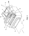
- Fig. 1 is a perspective view of an ink jet printer 1 according to the preferred embodiment, and Fig. 2 shows its paper path along which paper is transported.
- the paper path of printer 1 has a roll paper supply portion 2 including a roll paper loading mechanism and a slip form insertion opening 3 for inserting various types of cut-sheet forms of A4 or other size.
- the paper path carries roll paper 4 supplied from the supply portion 2, or a slip form 5 inserted into the insertion opening 3, past a common printing position 11 (indicated in Fig. 1 by a single dot-dash line).
- Roll paper 4 is typically used for printing receipts.
- the roll paper 4 is pulled from a paper roll 4A loaded in the supply portion 2, travels between paper guide 27 and pressure roller 15, past the printing position 11, and between platen roller 26 (also referred to as roll paper feed roller) and pressure roller 16. Note that the roll paper 4 is advanced by rotation of the platen roller 26.
- Slip forms 5 are used for printing sales records and similar forms.
- a slip form 5 is inserted into the insertion opening 3 and caught by paper feed roller 51 and pressure roller 52, advanced between paper feed roller 53 and pressure roller 54 past the printing position 11, and is then ejected from the printer after having passed between paper feed roller 55 and pressure roller 56 (see Fig. 3).
- a guide shaft 6 is disposed in parallel to the common printing position 11.
- An ink jet head 8 is mounted on a carriage 7, which travels bidirectionally along the guide shaft 6. It is therefore possible to print, by means of this ink jet head 8, as desired on the surface of either roll paper 4 or slip form 5 advanced to the common printing position 11.
- Ink is supplied through an ink tube (not shown in the figure) to the ink jet head 8 from an ink supply 10 disposed at a position typically adjacent to the roll paper supply portion 2.
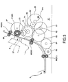
- FIG. 3 A typical configuration of a drive force transfer mechanism for use in printer 1 is described next with reference to Fig. 3 and Fig. 4.
- This drive force transfer mechanism uses a clutch mechanism to transfer rotation (torque) from a single drive motor to either a first gear train for roll paper transportation or a second gear train for slip form transportation, thereby rotatively driving platen roller 26 or paper feed rollers 51, 53, and 55.
- rotation rotation
- the drive force transfer mechanism comprises: a single drive motor 61; the first gear train for transferring motor rotation from a pinion 61a to the platen roller 26; the second gear train for transferring the motor rotation to paper feed rollers 51, 53, and 55; and a switching gear 62 for switching between these two gear trains.
- the switching gear 62 constantly engages the pinion 61a which is provided on and fixed to the motor shaft.
- the first gear train includes a first gear 71 for engaging switching gear 62, a second gear 72 coaxial with and fixed to first gear 71, a third gear 73, referred to as drive gear hereinafter, engaged with this second gear 72, and a paper feed gear 31, which is normally engaged with the drive gear 73.
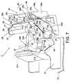
- the platen roller 26 is mounted on one end of a slide frame 25, which is a component of a cover 30 (see Fig. 7) for covering the roll paper supply portion 2.
- the paper feed gear 31 is fixed on one end of a center shaft 26a of platen roller 26 and coaxial therewith. When the cover is completely closed and locked, the paper feed gear 31 engages the drive gear 73. When the cover is open, the paper feed gear 31 is disengaged from the drive gear 73.
- gears 71 to 73 are fixed relative to a printer main frame 12 while paper feed gear 31 is fixed relative to the cover (in fact, the cover's slide frame 25 in this embodiment where the cover comprises multiple parts movable with respect to one another).
- Drive gear 73 is the last gear in the first gear train on the main frame side.
- the second gear train for slip form transportation includes a first gear 81 for engaging switching gear 62; a second gear 82 coaxial with and fixed to this first gear 81; a third gear 83 engaging this second gear 82; fourth and fifth gears 84 and 85 engaging this third gear 83; a sixth gear 86 engaging this fourth gear 84; a seventh gear 87 engaging this fifth gear 85; a paper feed roller drive gear 88 engaging this sixth gear 86; a paper feed roller drive gear 89 engaging the third gear 83; and a paper feed roller drive gear 90 engaging the seventh gear 87.
- the paper feed roller drive gear 88 is linked coaxially to paper feed roller 51; paper feed roller drive gear 89 is linked coaxially to paper feed roller 53; and paper feed roller drive gear 90 is linked coaxially to paper feed roller 55.
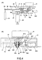
- the clutch mechanism for switching the transfer path of the drive motor's torque (referred to as drive train below) is described below with reference to Fig. 4.
- This clutch mechanism comprises the above-noted switching gear 62, and a solenoid 62B for moving the switching gear 62 along its center shaft 62a between a roll paper transport position, in which the gear's position is as indicated in Fig. 4 by a solid line, and a slip form transport position, in which the gear's position is as indicated by a dotted line in Fig. 4.
- the switching gear 62 comprises: a cylindrical part 621 disposed so that it can rotate freely and slide on center shaft 62a; an external gear 623 having its teeth formed on the outer circumferential surface of a ring flange 622, which has a cup-like shape to widen from the outside circumference of cylindrical part 621; and a ring flange 624 formed at a position on the outside circumference of cylindrical part 621 separated in the axial direction from ring flange 622.
- An annular channel 625 is formed between these ring flanges 622 and 624.
- One end of operating lever 626 used to slide switching gear 62 along the shaft 62a is inserted into this annular channel 625.
- This operating lever 626 is linked to an end part of operating rod 629 of solenoid 62B by way of intervening lever support 628 formed to support a bracket 627. It is therefore possible to slide the switching gear 62 and thereby switch the drive train simply by energizing or deenergizing the solenoid 62B.
- motor rotation is transferred through first to third gears 71, 72, and 73 to the paper feed gear 31 when the switching gear 62 is in the roll paper transport position (indicated by the solid line in Fig. 4 (A)). Platen roller 26 is thus rotatively driven, and roll paper 4 is advanced.
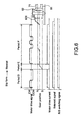
- Fig. 5 and Fig. 6 are timing charts referred to below to describe the switching operation (receipt to slip form or R/S switching) whereby the switching gear 62 is moved from the roll paper transport position to the slip form transport position, and the switching operation (slip form to receipt or S/R switching) whereby the switching gear 62 is moved from the slip form transport position to the roll paper transport position, respectively.
- this R/S switching signal is a cover-unlocked signal output from a detector for detecting whether the cover is locked or unlocked as described more fully below.
- the R/S switching signal can also be generated manually using an appropriate manual switch, for instance.
- the solenoid 62B When the R/S switching signal is applied, the solenoid 62B is operated (deenergized in Fig. 5, energized in Fig. 6) and the drive motor 61 is driven forward and rearward (i.e., clockwise and counterclockwise) to adjust the position of the switching gear 62 relative to the gear 71 (or 81) so that it may separate from the gear 71 (or 81) with which it is engaged (periods A and D in Fig. 5 and Fig. 6, respectively). Depending on whether the switching gear 62 is engaged with gear 71 or 81 at the start of this operation, switching gear 62 slides along shaft 62a in either period A or D, and separates from gear 71 or 81.
- the switching gear 62 will not necessarily disengage from gear 71 (or 81) within period A (or D). There is, therefore, a delay (periods B and E, respectively) of a specified time during which the controller for driving the clutch waits for the switching gear 62 to separate completely from gear 71 (or 81). The drive motor 61 is then again turned forward and rearward to allow the switching gear 62 to slide and adjust its position so that it engages the other gear 81 (or 71).
- the drive train is normally set to the roll paper transport side, and switching gear 62 is normally held in the position indicated by the solid line in Fig. 4 (A).
- the switching gear 62 is slid to the position indicated by the dotted line in Fig. 4 (A) by means of the clutch mechanism, thereby switching the drive train to the slip form transport side.
- the first gear train for roll paper transportation is decoupled from the motor and, thus, released from the rotation constraining force exerted by the drive motor 61 when the latter is not driven.
- roll paper supply portion 2 has a mounting frame 21 affixed to the main frame 12.
- This mounting frame 21 comprises a roll paper holder 22 into which roll paper 4 is loaded in the form of a paper roll 4A.
- the roll paper holder 22 has a semicircular curved part 22a of a specific width, and a rectangular opening 22b above the curved part 22a. Paper roll 4A can be replaced or loaded through this opening 22b.
- the opening 22b can be opened/closed by means of cover 30 comprising a first cover frame 23, the slide frame 25, and a second cover frame 28.
- the first cover frame 23 has a top plate part 23a with substantially the same rectangular shape as the opening 22b, and sides 23b and 23c, which have a specific height and are formed by bending the right and left sides of top plate part 23a perpendicularly to the top.
- each side 23b and 23c extends further downward, forming bottom ends 23d and 23e. These bottom ends 23d and 23e are pivotally supported on a shaft 24. The ends of shaft 24 are supported by mounting frame 21.
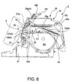
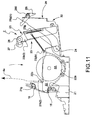
- the first cover frame 23 can thus pivot around shaft 24 between a closed position (shown in Fig. 8) whereat it closes the opening 22b, and an open position (shown in Fig. 11) whereat the opening 22b is open and unobstructed.
- Slide frame 25 is mounted on this first cover frame 23.
- Slide frame 25 both pivots in conjunction with the first cover frame 23 and slides relative to the first cover frame 23.
- the platen roller 26 and the paper guide 27 for guiding roll paper 4 to the platen roller 26 are mounted at the front edge of the slide frame 25.
- the slide frame 25 has a rectangular top plate 25a that contacts the inside of the top plate part 23a of first cover frame 23, and sides 25b and 25c, which have a specific height and are formed by bending the right and left sides of top plate 25a perpendicularly to the top.
- Guide slots 25d and 25f are formed in the front-to-back direction in the top plate 25a.
- Guide pins 23q and 23r fixed to top plate part 23a of first cover frame 23 pass through these guide slots 25d and 25f.
- a snap ring 23h and 23i is attached at the projecting bottom ends of these guide pins 23q and 23r to hold the slide frame 25 so that it is slidably held on the inside of first cover frame 23 as shown in Fig. 12 (A).
- a coil spring 23g is connected between the rear guide pin 23r and a spring catch 25g disposed at the front end of the slide frame 25. This coil spring 23g biases the slide frame 25 to the rear.
- the platen roller 26 is disposed between front ends 25h and 25i of sides 25b and 25c of the slide frame 25 with the ends of the platen roller shaft rotatively supported at the front ends 25h and 25i.
- Paper guide 27 is formed below the platen roller 26 and has a convex circular arc shaped surface tangential to the outside surface of platen roller 26.
- pressure roller 16 presses against the outside surface of the platen roller 26 with a specific elastic force. More specifically, the center shaft 16a of pressure roller 16 can be moved slightly to approach or separate from platen roller 26, and is normally urged to platen roller 26 by spring tension. Therefore, when the platen roller 26 is positioned in its operating position in resistance to this spring tension, roll paper 4 is pressed against the outside surface of the platen roller 26 by means of pressure roller 16 as a result of this constant spring tension. Roll paper 4 thus held between these two rollers can then be advanced by rotatively driving platen roller 26.
- a slightly larger second cover frame 28 is disposed over first cover frame 23.
- This second cover frame 28 comprises top panel 28a and sides 28b and 28c, which are bent perpendicularly from both sides of top panel 28a. The rear ends of sides 28b and 28c extend further downward, and are pivotally supported on shaft 24.
- first cover frame 23 to which slide frame 25 is attached also pivots.
- the second cover frame 28 continues to pivot independently. This independent pivoting action of the second cover frame 28 causes the slide frame 25 to slide forward or rearward relative to the first cover frame 23.
- a linkage mechanism 29 for converting the independent pivoting motion of the second cover frame 28 to the sliding motion of the slide frame 25 comprises a connecting shaft 28d and three oval connecting holes 25j.
- the connecting shaft 28d spans the distance between the sides 28b and 28c of second cover frame 28 at a position above and at the rear of the second cover frame 28.
- the connecting holes 25j are provided at the rear of slide frame 25.
- the connecting shaft 28d passes through the connecting holes 25j.
- the long axis of the oval connecting holes 25j is oriented substantially perpendicularly to the slide frame 25 so that the connecting holes 25j do not interfere with the independent pivoting action of the second cover frame 28.
- the slide frame 25 is urged constantly in the retracting direction by coil spring 23g.
- the tension of the extended coil spring 23g thus causes the slide frame 25 to return to the retracted position when the force holding the second cover frame 28 horizontal and closed as shown in Fig. 8 is released.
- This sliding action also causes the second cover frame 28 to pivot in the opening direction to the posture shown in Fig. 9.
- a locking lever 280 is disposed at a front part of the second cover frame 28 as a means of locking the second cover frame 28 in the closed position shown in Fig. 8.
- hooks 28g and 28h formed on the end of each locking lever 280 engage a corresponding catch 21g and 21h on the edge of the opposing mounting frame 21.
- the hooks 28g and 28h engage the catches 21g and 21h by rotating back and engaging the catches 21g and 21h from below.
- a torsion spring (not shown in the figure) constantly urges locking lever 280 in the direction causing the hooks to rotate forward and up against the catches.
- hooks 28g and 28h are forced to pivot slightly back in resistance to the torsion spring until the hooks pass the edge of the corresponding catch and then travel forward and up again to engage the respective catch 21g and 21h on the mounting frame 21.
- end 28i of the locking lever 280 is raised, thereby causing the hook on the bottom end of the locking lever 280 to rotate downward and disengage the catch.
- Roll paper supply portion 2 also has a mechanism for precisely positioning the platen roller 26 in its operating position when the second cover frame 28 is closed as described above. More specifically, positioning pins 25k and 25l project horizontally to both sides at the front of sides 25b and 25c of slide frame 25. Corresponding to these positioning pins 25k and 25l on the mounting frame 21 are semicircular channels 21k and 21l so that when the slide frame 25 is closed the positioning pins 25k and 25l slide horizontally into the positioning channels 21k and 21l.
- a respective coil spring 23j and 23k (only 23j is shown in the figures) is stretched between the sides 21b and 21c of the mounting frame 21 and the corresponding sides 23b and 23c of the first cover frame 23.
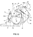
- These coil springs 23j and 23k are disposed such that when the second cover frame 28, slide frame 25, and first cover frame 23 are opened and closed by being pivoted on shaft 24 and pass the pivot position shown in Fig. 10 (illustrating a second intermediate position of the cover) where the center of gravity of the frames is directly above shaft 24, the distance between the catches on the ends of each spring increases as the frames 28, 25, and 23 continue to move.
- Printer 1 of this embodiment further comprises a locked/unlocked detection mechanism (simply called LUD mechanism below) for detecting whether the cover 30 is locked in the closed position or whether the locking has been released.
- LUD mechanism a locked/unlocked detection mechanism
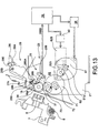
- Fig. 13 shows the part of the printer where the LUD mechanism is mounted, and the major components of the printer control system.
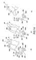
- Fig. 14 illustrates how the LUD mechanism works. It is to be noted that this LUD mechanism is omitted from Figs. 1 to 12 for the convenience of showing the other component parts.
- the LUD mechanism detects whether the locking lever 280 is locked to the mounting frame 21 or has been released from the locked position.
- the LUD mechanism comprises a basically L-shaped pivoting lever 285, which pivots around an axis of rotation when pushed by the hook 28g, 28h of the corresponding locking lever 280, and an optical sensor, here in the form of a photointerrupter 288 for detecting the position of the pivoting lever 285.
- the pivoting lever 285 and photointerrupter 288 are supported on the mounting frame 21.
- the pivoting lever 285 is, more specifically, pivotally mounted by means of a pivot pin 289 attached at the bend in the pivoting lever 285.
- the pivoting lever 285 is normally urged in the direction opposite to arrow 285A in Fig. 13 by a spring (not shown in the figure).
- An engaging pin 286 is disposed at the top end of pivoting lever 285. When the cover 30 is being closed, this engaging pin 286 contacts the front edge of one locking lever hook 28h just before the cover reaches its final closed position. As the cover 30 then continues to move into its final closed position illustrated in Fig. 8, hook 28h pushing against this engaging pin 286 thereby causing pivoting lever 285 to pivot in the direction of arrow 285A to the position indicated by the solid line in Fig. 13.
- the hooks 28g and 28h of the locking lever 280 engage the catches 21g and 21h, respectively, on the mounting frame 21 and, thus, lock the cover 30 in the closed position.
- This locked position is shown in Fig. 14 (a).
- the other end 287 of the pivoting lever 285 extends into the detection slot 288a of the photointerrupter 288.
- the photointerrupter 288 thus outputs a detection signal (referred to as cover-locked signal) indicating that the hook 28h of the locking lever 280 is locked.
- Fig. 14 (c) shows the cover 30 when it has pivoted slightly towards the fully open position.
- Fig. 13 shows the controller and corresponding mechanical parts of printer 1.
- the controller of printer 1 comprises a drive control unit 39 typically having a microprocessor with a CPU, a ROM for storing the program to be run by the CPU, and a working RAM, similar to a common ink jet printer. That is, the controller described below is composed of primarily the same CPU, ROM, and RAM as conventional printers with the CPU performing the process for reducing or releasing the constraining force on the paper feed gear described below according to a program stored in ROM and/or RAM.
- drive control of the ink jet head 8 and paper feed control of roll paper and slip forms by this drive control unit 39 is substantially the same as in a common ink jet printer. Further description and presentation in the accompanying figures is therefore omitted herein; only those parts associated with drive control as it relates to the present invention are described.
- the drive control unit 39 controls drive motor 61 by means of motor driver 38, and controls operation of the solenoid 62B by means of driver 40.
- the detection signal 288S generated and output by the photointerrupter 288 of the LUD mechanism as described above is supplied to the drive control unit 39.
- the drive control unit 39 performs an operation for releasing the force, if any, that prevents or hinders the meshing drive gear 73 and paper feed gear 31 to disengage from one another and thus constrains opening the cover. This operation is referred to below as a constraint releasing operation.
- this embodiment has the drive control unit 39 driving the above-noted clutch mechanism to switch the drive train downstream from the drive motor 61 from the roll paper transportation gear train to the slip form transportation gear train.
- this clutch mechanism comprises solenoid 62B, switching gear 62, first gear 71, and first gear 81.
- Opening and closing roll paper holder 22 of the roll paper supply portion 2 in printer 1 of this embodiment is described next below with reference to Figs. 8 to 11, 13, and 14.
- Fig. 8 shows the cover 30 in a first or closed position in which the first cover frame 23 covers the opening 22b, the slide frame 25 is in its projected position holding the platen roller 26 in its operation position with drive gear 71 and paper feed gear 31 engaged with one another, and the second cover frame 28 is locked in its closed position.
- Fig. 11 shows the cover in a second or open position with the first cover frame 23, the slide frame 25 and the second cover frame 28 each in its fully open position.
- Figs. 9 and 10 illustrate a first and a second intermediate position on the cover's way from the first position of Fig. 8 to the second position of Fig. 11. Note that in this embodiment the paper feed gear 31 becomes disengaged from the drive gear 73 while the cover is moving from the first position in Fig. 8 to the first intermediate position, i.e., before the second position is reached.
- the pivoting lever 285, therefore, leaves the detection slot 288a of the photointerrupter 288, and the photointerrupter 288 thus detects that the locking of cover 30 has been released. More specifically, the detection signal of the photointerrupter 288 is output as a cover-unlocked signal to the drive control unit 39 of the ink jet printer 1.
- the drive control unit 39 When the drive control unit 39 detects this signal, it applies a drive signal to the solenoid 62B of the clutch mechanism, thereby causing the switching gear 62 to slide from the roll paper transport position (indicated with a solid line in Fig. 4) to the slip form transport position (indicated with a dotted line in Fig. 4).
- This switching operation follows the sequence shown in Fig. 5 and explained before.
- the roll paper transportation gear train (gears 71 to 73 and 31) is thus disengaged from the drive train connected to the drive motor 61, thereby reducing or releasing the constraining force preventing free gear rotation.
- the drive gear 73 on the main frame side and the paper feed gear 31 engaged therewith are thus both able to turn freely. It is therefore possible to easily disengage the meshed drive gears. As a result, the cover 30 can be opened with little force. This is true even if the paper feed gear is blocked by such as a paper jam. In that case only the drive gear 73 is freely rotatable which is sufficient, however, to allow the two gears to rotate relative to each other and, thus, to disengage from each other.
- the paper roll 4A (see Fig. 10) in the roll paper holder can be replaced.
- the paper roll 4A can be easily placed into and removed from the roll paper holder because the opening 22b is unobstructed. It is also easy to position the leading part 4a of the roll paper 4 because the platen roller 26 and paper guide 27 are also removed from the roll paper holder together with the slide frame 25.
- the second cover frame 28 After loading a paper roll 4A, the second cover frame 28 is rotated in the closing direction.
- the second cover frame 28, slide frame 25, and first cover frame 23 thus pivot together through the position shown in Fig. 10 until the first cover frame 23 closes the opening 22b as shown in Fig. 9.
- the first cover frame 23 thus engages the edge of the opening 22b and pivots no further.
- the slide frame 25 disposed slidably on the first cover frame 23 also stops pivoting.
- the second cover frame 28, therefore, pivots independently as it continues to close from this position.
- the positioning pins 25k and 25l at the front sides of the slide frame 25 enter the channels 21k and 21l in the mounting frame 21, thus stopping the sliding motion and defining the operating position.
- the channels 21k and 21l assure that the platen roller 26 and paper guide 27 are held in a predetermined operating position at which a specific gap to the ink jet head 8 is established and held.
- the drive control unit 39 When the drive control unit 39 then detects this cover-locked signal, it drives the solenoid 62B of the clutch mechanism to slide the switching gear 62 from the slip form transport position (dotted line in Fig. 4) to the roll paper transport position (solid line in Fig. 4).
- the operating sequence in this case is as shown in Fig. 6 and explained before. This operation completes the drive train for roll paper transportation. Thereafter, the drive control unit 39 drives drive motor 61 through motor driver 38 to advance the roll paper, and synchronously drives the ink jet head 8 to print as desired on the roll paper.
- additional means are provided for switching the clutch mechanism between the two gear trains depending on whether roll paper or slip forms are to be printed. Such means are not directly related to the invention and will not be described in further detail.
- the drive train is switched to the slip form side to release or reduce any constraining force that may oppose the rotation of the paper feed gear 31 relative to the drive gear 73 which relative rotation is necessary to allow the two gears to disengage from one another in response to the application of only a little force.
- this controller it is alternatively possible, as shown in Fig. 15 for example, for this controller to stop, when the photointerrupter 288 detects that the cover is unlocked, supplying the holding current typically applied to drive motor 61 to hold it in a fixed position. With the holding current removed, the drive motor is allowed to turn freely. This can be accomplished by the motor controller 39B of the drive control unit 39.
- This configuration also effectively reduces or releases the constraining force of drive motor 61 on the roll paper transportation gear train. Little force is therefore required to disengage the paper feed gear 31 from the drive gear 73.
- the controller can also be comprised to actively disengage the paper feed gear 31 and the drive gear 73 by driving the drive motor 61 reverse to the paper transportation direction for a specified time when the photointerrupter 288 detects the cover to be unlocked. In this case, too, the paper feed gear 31 can be disengaged from the drive gear 73 with little force required.
- This configuration is particularly advantageous when the roll paper jams. More specifically, when the roll paper jams the roll paper is typically stuck in the gap between the platen roller 26 and the member opposing the outside surface of the platen roller 26. When this happens the platen roller 26 cannot turn, and the paper feed gear 31 affixed coaxially to the platen roller 26 also cannot turn. As a result, the cover 30 to which the platen roller 26 is attached cannot be opened as explained before.
- the cover 30 To recover from such a paper jam, the cover 30 must be opened and the jammed roll paper removed. Even though the cover 30 itself is blocked in such case, the locking lever 280 will not be affected and can be pivoted to the unlocked position (indicated by the dotted line in Fig. 8), thereby causing the cover-unlocked signal to be output from the photointerrupter 288.
- the drive motor 61 is driven in reverse for a specific time by the motor driver 38. If the cover 30 is opened in conjunction with the reverse motor rotation, the paper feed gear 31 and the drive gear 73 can be easily disengaged. It is thus even easier to open the cover 30. Jammed roll paper can then be removed, and the platen roller 26 can again be turned.
- the present invention is applicable to a variety of different printer structures it is particularly advantageous in case of the embodiment explained above in which the paper feed gear 31 engages the drive gear 73 (or disengages from it) while moving in a direction substantially tangential to the drive gear. Because the platen roller 26 and the paper feed gear 31 are mounted on the slide frame 25, the axis of paper feed gear 31 performs a translational motion relative to the drive gear 73 as the two gears are engaged with or disengaged from one another.
- the drive gear is located at such position that the locus of paper feed gear's axis during the engaging and disengaging motion is parallel to a line more or less tangential to the drive gear.
Landscapes
- Accessory Devices And Overall Control Thereof (AREA)
- Handling Of Sheets (AREA)
- Unwinding Webs (AREA)
- Replacement Of Web Rolls (AREA)
- Handling Of Continuous Sheets Of Paper (AREA)
Applications Claiming Priority (4)
| Application Number | Priority Date | Filing Date | Title |
|---|---|---|---|
| JP10281797A JP2000108457A (ja) | 1998-10-02 | 1998-10-02 | ロール紙プリンタ |
| JP28179998 | 1998-10-02 | ||
| JP28179998 | 1998-10-02 | ||
| JP28179798 | 1998-10-02 |
Publications (3)
| Publication Number | Publication Date |
|---|---|
| EP0990533A2 true EP0990533A2 (de) | 2000-04-05 |
| EP0990533A3 EP0990533A3 (de) | 2000-06-28 |
| EP0990533B1 EP0990533B1 (de) | 2004-12-22 |
Family
ID=26554335
Family Applications (1)
| Application Number | Title | Priority Date | Filing Date |
|---|---|---|---|
| EP99119465A Expired - Lifetime EP0990533B1 (de) | 1998-10-02 | 1999-09-30 | Drucker und Verfahren zu dessen Steuerung |
Country Status (3)
| Country | Link |
|---|---|
| US (1) | US6345782B1 (de) |
| EP (1) | EP0990533B1 (de) |
| DE (1) | DE69922757T2 (de) |
Cited By (5)
| Publication number | Priority date | Publication date | Assignee | Title |
|---|---|---|---|---|
| EP1379456A4 (de) * | 2001-02-23 | 2006-05-17 | Ascom Hasler Mailing Sys Inc | Zugang zu briefpfad |
| EP1950049A2 (de) | 2007-01-24 | 2008-07-30 | Seiko Instruments Inc. | Vorrichtung zur Verarbeitung von fortlaufenden Blättern und Verfahren zur Einrichtung eines Walzenkörpers auf der Vorrichtung zur Verarbeitung von fortlaufenden Blättern |
| EP2062736A1 (de) * | 2007-11-20 | 2009-05-27 | Seiko Epson Corporation | Drucker |
| WO2009083824A1 (en) * | 2007-12-28 | 2009-07-09 | Arcelik Anonim Sirketi | A cash register |
| CN104418142A (zh) * | 2013-09-11 | 2015-03-18 | 芯发威达电子(上海)有限公司 | 具有侦测上盖开合功能的纸卷装置 |
Families Citing this family (18)
| Publication number | Priority date | Publication date | Assignee | Title |
|---|---|---|---|---|
| JP2001233527A (ja) * | 2000-02-22 | 2001-08-28 | Riso Kagaku Corp | 排紙装置及び印刷装置 |
| US6629796B2 (en) * | 2000-04-12 | 2003-10-07 | Seiko Epson Corporation | Printer |
| KR100385586B1 (ko) * | 2000-12-21 | 2003-05-27 | 삼성전기주식회사 | 프린터용 클램쉘 장치 |
| FR2825317B1 (fr) * | 2001-05-29 | 2003-10-31 | Sagem | Machine d'impression a volet de deverrouillage du capot |
| ES2260356T3 (es) * | 2001-06-25 | 2006-11-01 | Seiko Epson Corporation | Impresora. |
| US7125182B2 (en) * | 2004-02-17 | 2006-10-24 | Paxar Americas, Inc. | Printer |
| KR100557013B1 (ko) * | 2004-04-16 | 2006-03-03 | 주식회사 빅솔론 | 회전식 플라텐을 구비한 도트 프린터 |
| JP4409344B2 (ja) * | 2004-04-20 | 2010-02-03 | スター精密株式会社 | プリンタ |
| JP4407631B2 (ja) * | 2005-12-15 | 2010-02-03 | ソニー株式会社 | ロール紙給紙機構、ロール紙給紙カセット、及び画像形成装置 |
| JP2008070522A (ja) * | 2006-09-13 | 2008-03-27 | Ricoh Co Ltd | 画像形成装置 |
| US7986420B2 (en) * | 2006-11-29 | 2011-07-26 | International Business Machines Corporation | Sensing paper jam, out-of-paper, and cover open in a printer |
| JP4930247B2 (ja) * | 2007-07-26 | 2012-05-16 | ブラザー工業株式会社 | テープ印刷装置 |
| JP5082749B2 (ja) | 2007-10-15 | 2012-11-28 | セイコーエプソン株式会社 | プリンタ |
| JP5459541B2 (ja) | 2009-11-17 | 2014-04-02 | 株式会社リコー | シート材供給装置及び画像形成装置 |
| JP5671858B2 (ja) * | 2010-07-15 | 2015-02-18 | セイコーエプソン株式会社 | 印刷装置、ロール径算出方法、及び、プログラム |
| JP5757768B2 (ja) * | 2011-04-04 | 2015-07-29 | 富士通コンポーネント株式会社 | プリンタ |
| IT202000025234A1 (it) * | 2020-10-26 | 2022-04-26 | K F I S R L | Stampante con apertura facilitata e chiusura fermamente assicurata |
| JP7746014B2 (ja) * | 2021-02-02 | 2025-09-30 | 東芝テック株式会社 | 用紙収納装置 |
Citations (5)
| Publication number | Priority date | Publication date | Assignee | Title |
|---|---|---|---|---|
| JPS6420414A (en) | 1987-07-15 | 1989-01-24 | Mazda Motor | On-vehicle display device |
| US5061095A (en) | 1989-11-14 | 1991-10-29 | Seiko Epson Corporation | Printer for printing on multiple types of printing sheets |
| JPH05147284A (ja) | 1991-11-30 | 1993-06-15 | Mita Ind Co Ltd | インクジエツト記録装置 |
| JPH0679855B2 (ja) | 1986-10-15 | 1994-10-12 | 株式会社セコニツク | 記録装置 |
| EP0925947A1 (de) | 1997-04-02 | 1999-06-30 | Seiko Epson Corporation | Papierrollenlademechanismus für drucker |
Family Cites Families (9)
| Publication number | Priority date | Publication date | Assignee | Title |
|---|---|---|---|---|
| JPH0259534A (ja) | 1988-08-17 | 1990-02-28 | China Petrochem Dev Corp | オルトアルキルフエノールの製造方法 |
| JPH0413371A (ja) | 1990-05-01 | 1992-01-17 | Canon Inc | 画像処理装置 |
| US5400146A (en) | 1991-05-29 | 1995-03-21 | Canon Kabushiki Kaisha | Image formation apparatus |
| JPH04351156A (ja) | 1991-05-29 | 1992-12-04 | Canon Inc | 開閉部材のロック検出機構 |
| DE4210777C2 (de) | 1992-04-01 | 1995-07-06 | Roland Man Druckmasch | Zugwalzenpaar, insbesondere an Druckmaschinen |
| JPH07309506A (ja) | 1994-05-18 | 1995-11-28 | Ricoh Co Ltd | 画像形成装置 |
| JPH0818705A (ja) | 1994-07-04 | 1996-01-19 | Murata Mach Ltd | 開閉カバーのロック機構 |
| AU700935B2 (en) * | 1995-11-13 | 1999-01-14 | Zih Corporation | Thermal printer with spring biased drive roller/platen |
| JPH1020414A (ja) | 1996-07-02 | 1998-01-23 | Murata Mach Ltd | 開閉カバー機構 |
-
1999
- 1999-09-30 EP EP99119465A patent/EP0990533B1/de not_active Expired - Lifetime
- 1999-09-30 DE DE69922757T patent/DE69922757T2/de not_active Expired - Lifetime
- 1999-10-01 US US09/411,333 patent/US6345782B1/en not_active Expired - Lifetime
Patent Citations (5)
| Publication number | Priority date | Publication date | Assignee | Title |
|---|---|---|---|---|
| JPH0679855B2 (ja) | 1986-10-15 | 1994-10-12 | 株式会社セコニツク | 記録装置 |
| JPS6420414A (en) | 1987-07-15 | 1989-01-24 | Mazda Motor | On-vehicle display device |
| US5061095A (en) | 1989-11-14 | 1991-10-29 | Seiko Epson Corporation | Printer for printing on multiple types of printing sheets |
| JPH05147284A (ja) | 1991-11-30 | 1993-06-15 | Mita Ind Co Ltd | インクジエツト記録装置 |
| EP0925947A1 (de) | 1997-04-02 | 1999-06-30 | Seiko Epson Corporation | Papierrollenlademechanismus für drucker |
Cited By (8)
| Publication number | Priority date | Publication date | Assignee | Title |
|---|---|---|---|---|
| EP1379456A4 (de) * | 2001-02-23 | 2006-05-17 | Ascom Hasler Mailing Sys Inc | Zugang zu briefpfad |
| EP1950049A2 (de) | 2007-01-24 | 2008-07-30 | Seiko Instruments Inc. | Vorrichtung zur Verarbeitung von fortlaufenden Blättern und Verfahren zur Einrichtung eines Walzenkörpers auf der Vorrichtung zur Verarbeitung von fortlaufenden Blättern |
| EP1950049A3 (de) * | 2007-01-24 | 2009-04-01 | Seiko Instruments Inc. | Vorrichtung zur Verarbeitung von fortlaufenden Blättern und Verfahren zur Einrichtung eines Walzenkörpers auf der Vorrichtung zur Verarbeitung von fortlaufenden Blättern |
| US7975955B2 (en) | 2007-01-24 | 2011-07-12 | Kiyokazu Takeuchi | Continuous sheet processing apparatus and method of setting a roll body in the continuous sheet processing apparatus |
| EP2062736A1 (de) * | 2007-11-20 | 2009-05-27 | Seiko Epson Corporation | Drucker |
| US8157461B2 (en) | 2007-11-20 | 2012-04-17 | Seiko Epson Corporation | Printer |
| WO2009083824A1 (en) * | 2007-12-28 | 2009-07-09 | Arcelik Anonim Sirketi | A cash register |
| CN104418142A (zh) * | 2013-09-11 | 2015-03-18 | 芯发威达电子(上海)有限公司 | 具有侦测上盖开合功能的纸卷装置 |
Also Published As
| Publication number | Publication date |
|---|---|
| EP0990533A3 (de) | 2000-06-28 |
| DE69922757D1 (de) | 2005-01-27 |
| EP0990533B1 (de) | 2004-12-22 |
| US6345782B1 (en) | 2002-02-12 |
| DE69922757T2 (de) | 2005-12-15 |
Similar Documents
| Publication | Publication Date | Title |
|---|---|---|
| EP0990533B1 (de) | Drucker und Verfahren zu dessen Steuerung | |
| EP1086821B1 (de) | Drucker | |
| KR100520579B1 (ko) | 인쇄-매체 이송장치, 인쇄-매체 이송장치를 포함하는 프린터, 인쇄-매체 이송장치에 이용되는 제어방법 및 인쇄-매체 이송장치의 제어기에 의해 실행되는 컴퓨터 프로그램을 포함하는 저장매체 | |
| JP2001121764A (ja) | プリンタ | |
| US6139011A (en) | Jam clearance for printer path by manual operation | |
| EP1000760B1 (de) | Drucker | |
| US7410315B2 (en) | Paper discharge mechanism for a printer, and a printer | |
| EP0458461A2 (de) | Selbstjustierender Wärmedruckkopf und Papierladevorrichtung | |
| US5868508A (en) | Printer structure for facilitating installation and removal of an ink ribbon cassette | |
| JP2015134686A (ja) | 巻取装置および印刷巻取システム | |
| US7731438B2 (en) | Sheet bundle printer and sheet bundle printing system | |
| JP3700461B2 (ja) | プリンタ | |
| JPH0616766Y2 (ja) | プリンタトップカバー | |
| JP3757705B2 (ja) | プリンタ及びその制御方法 | |
| US7641184B2 (en) | Image reading and recording apparatus | |
| JP2025114235A (ja) | ロール支持装置、及び記録装置 | |
| JP2000108439A (ja) | ロール紙用プリンタ | |
| JP3654008B2 (ja) | ロール紙用プリンタ | |
| JP3565043B2 (ja) | プリンタのロール紙装填機構 | |
| US6752495B2 (en) | Image forming device | |
| JP3743157B2 (ja) | プリンタ | |
| EP0516061A1 (de) | Bilderzeugungsgerät | |
| JP2000108457A (ja) | ロール紙プリンタ | |
| US20100051665A1 (en) | Transportation guide mechanism and recording device having same | |
| JP3704945B2 (ja) | プリンタ |
Legal Events
| Date | Code | Title | Description |
|---|---|---|---|
| PUAI | Public reference made under article 153(3) epc to a published international application that has entered the european phase |
Free format text: ORIGINAL CODE: 0009012 |
|
| AK | Designated contracting states |
Kind code of ref document: A2 Designated state(s): CH DE FR GB IT LI |
|
| AX | Request for extension of the european patent |
Free format text: AL;LT;LV;MK;RO;SI |
|
| PUAL | Search report despatched |
Free format text: ORIGINAL CODE: 0009013 |
|
| AK | Designated contracting states |
Kind code of ref document: A3 Designated state(s): AT BE CH CY DE DK ES FI FR GB GR IE IT LI LU MC NL PT SE |
|
| AX | Request for extension of the european patent |
Free format text: AL;LT;LV;MK;RO;SI |
|
| 17P | Request for examination filed |
Effective date: 20000727 |
|
| AKX | Designation fees paid |
Free format text: CH DE FR GB IT LI |
|
| GRAP | Despatch of communication of intention to grant a patent |
Free format text: ORIGINAL CODE: EPIDOSNIGR1 |
|
| GRAS | Grant fee paid |
Free format text: ORIGINAL CODE: EPIDOSNIGR3 |
|
| GRAA | (expected) grant |
Free format text: ORIGINAL CODE: 0009210 |
|
| AK | Designated contracting states |
Kind code of ref document: B1 Designated state(s): CH DE FR GB IT LI |
|
| REG | Reference to a national code |
Ref country code: GB Ref legal event code: FG4D |
|
| REG | Reference to a national code |
Ref country code: CH Ref legal event code: NV Representative=s name: E. BLUM & CO. PATENTANWAELTE Ref country code: CH Ref legal event code: EP |
|
| REF | Corresponds to: |
Ref document number: 69922757 Country of ref document: DE Date of ref document: 20050127 Kind code of ref document: P |
|
| PLBE | No opposition filed within time limit |
Free format text: ORIGINAL CODE: 0009261 |
|
| STAA | Information on the status of an ep patent application or granted ep patent |
Free format text: STATUS: NO OPPOSITION FILED WITHIN TIME LIMIT |
|
| ET | Fr: translation filed | ||
| 26N | No opposition filed |
Effective date: 20050923 |
|
| REG | Reference to a national code |
Ref country code: CH Ref legal event code: PFA Owner name: SEIKO EPSON CORPORATION Free format text: SEIKO EPSON CORPORATION#4-1, NISHI-SHINJUKU 2-CHOME#SHINJUKU-KU, TOKYO 163-0811 (JP) -TRANSFER TO- SEIKO EPSON CORPORATION#4-1, NISHI-SHINJUKU 2-CHOME#SHINJUKU-KU, TOKYO 163-0811 (JP) |
|
| REG | Reference to a national code |
Ref country code: FR Ref legal event code: PLFP Year of fee payment: 18 |
|
| PGFP | Annual fee paid to national office [announced via postgrant information from national office to epo] |
Ref country code: GB Payment date: 20160928 Year of fee payment: 18 Ref country code: CH Payment date: 20160914 Year of fee payment: 18 Ref country code: IT Payment date: 20160921 Year of fee payment: 18 |
|
| PGFP | Annual fee paid to national office [announced via postgrant information from national office to epo] |
Ref country code: FR Payment date: 20160816 Year of fee payment: 18 |
|
| PGFP | Annual fee paid to national office [announced via postgrant information from national office to epo] |
Ref country code: DE Payment date: 20160927 Year of fee payment: 18 |
|
| REG | Reference to a national code |
Ref country code: DE Ref legal event code: R119 Ref document number: 69922757 Country of ref document: DE |
|
| REG | Reference to a national code |
Ref country code: CH Ref legal event code: PL |
|
| GBPC | Gb: european patent ceased through non-payment of renewal fee |
Effective date: 20170930 |
|
| REG | Reference to a national code |
Ref country code: FR Ref legal event code: ST Effective date: 20180531 |
|
| PG25 | Lapsed in a contracting state [announced via postgrant information from national office to epo] |
Ref country code: GB Free format text: LAPSE BECAUSE OF NON-PAYMENT OF DUE FEES Effective date: 20170930 Ref country code: DE Free format text: LAPSE BECAUSE OF NON-PAYMENT OF DUE FEES Effective date: 20180404 Ref country code: CH Free format text: LAPSE BECAUSE OF NON-PAYMENT OF DUE FEES Effective date: 20170930 Ref country code: LI Free format text: LAPSE BECAUSE OF NON-PAYMENT OF DUE FEES Effective date: 20170930 |
|
| PG25 | Lapsed in a contracting state [announced via postgrant information from national office to epo] |
Ref country code: IT Free format text: LAPSE BECAUSE OF NON-PAYMENT OF DUE FEES Effective date: 20170930 Ref country code: FR Free format text: LAPSE BECAUSE OF NON-PAYMENT OF DUE FEES Effective date: 20171002 |