EP0990802A2 - Elektrohydraulische Einrichtung zur Geschwindigkeitssteuerung eines hydraulischen Hubzylinders - Google Patents
Elektrohydraulische Einrichtung zur Geschwindigkeitssteuerung eines hydraulischen Hubzylinders Download PDFInfo
- Publication number
- EP0990802A2 EP0990802A2 EP99114323A EP99114323A EP0990802A2 EP 0990802 A2 EP0990802 A2 EP 0990802A2 EP 99114323 A EP99114323 A EP 99114323A EP 99114323 A EP99114323 A EP 99114323A EP 0990802 A2 EP0990802 A2 EP 0990802A2
- Authority
- EP
- European Patent Office
- Prior art keywords
- lifting
- throttle valve
- control device
- electric motor
- load
- Prior art date
- Legal status (The legal status is an assumption and is not a legal conclusion. Google has not performed a legal analysis and makes no representation as to the accuracy of the status listed.)
- Granted
Links
- 238000000034 method Methods 0.000 claims abstract description 16
- 230000001419 dependent effect Effects 0.000 claims abstract description 10
- 230000008569 process Effects 0.000 claims description 6
- 230000003111 delayed effect Effects 0.000 claims description 3
- 239000004020 conductor Substances 0.000 abstract 1
- 230000006870 function Effects 0.000 description 10
- 230000008901 benefit Effects 0.000 description 3
- 238000011144 upstream manufacturing Methods 0.000 description 3
- 230000002349 favourable effect Effects 0.000 description 2
- 238000005259 measurement Methods 0.000 description 2
- 230000004913 activation Effects 0.000 description 1
- 230000006399 behavior Effects 0.000 description 1
- 238000011161 development Methods 0.000 description 1
- 230000018109 developmental process Effects 0.000 description 1
- 230000000694 effects Effects 0.000 description 1
- 230000005611 electricity Effects 0.000 description 1
- 230000002441 reversible effect Effects 0.000 description 1
- 230000001960 triggered effect Effects 0.000 description 1
Images

Classifications
-
- F—MECHANICAL ENGINEERING; LIGHTING; HEATING; WEAPONS; BLASTING
- F15—FLUID-PRESSURE ACTUATORS; HYDRAULICS OR PNEUMATICS IN GENERAL
- F15B—SYSTEMS ACTING BY MEANS OF FLUIDS IN GENERAL; FLUID-PRESSURE ACTUATORS, e.g. SERVOMOTORS; DETAILS OF FLUID-PRESSURE SYSTEMS, NOT OTHERWISE PROVIDED FOR
- F15B11/00—Servomotor systems without provision for follow-up action; Circuits therefor
- F15B11/02—Systems essentially incorporating special features for controlling the speed or actuating force of an output member
- F15B11/04—Systems essentially incorporating special features for controlling the speed or actuating force of an output member for controlling the speed
- F15B11/044—Systems essentially incorporating special features for controlling the speed or actuating force of an output member for controlling the speed by means in the return line, i.e. "meter out"
-
- F—MECHANICAL ENGINEERING; LIGHTING; HEATING; WEAPONS; BLASTING
- F15—FLUID-PRESSURE ACTUATORS; HYDRAULICS OR PNEUMATICS IN GENERAL
- F15B—SYSTEMS ACTING BY MEANS OF FLUIDS IN GENERAL; FLUID-PRESSURE ACTUATORS, e.g. SERVOMOTORS; DETAILS OF FLUID-PRESSURE SYSTEMS, NOT OTHERWISE PROVIDED FOR
- F15B11/00—Servomotor systems without provision for follow-up action; Circuits therefor
- F15B11/02—Systems essentially incorporating special features for controlling the speed or actuating force of an output member
- F15B11/04—Systems essentially incorporating special features for controlling the speed or actuating force of an output member for controlling the speed
- F15B11/05—Systems essentially incorporating special features for controlling the speed or actuating force of an output member for controlling the speed specially adapted to maintain constant speed, e.g. pressure-compensated, load-responsive
- F15B11/055—Systems essentially incorporating special features for controlling the speed or actuating force of an output member for controlling the speed specially adapted to maintain constant speed, e.g. pressure-compensated, load-responsive by adjusting the pump output or bypass
-
- F—MECHANICAL ENGINEERING; LIGHTING; HEATING; WEAPONS; BLASTING
- F15—FLUID-PRESSURE ACTUATORS; HYDRAULICS OR PNEUMATICS IN GENERAL
- F15B—SYSTEMS ACTING BY MEANS OF FLUIDS IN GENERAL; FLUID-PRESSURE ACTUATORS, e.g. SERVOMOTORS; DETAILS OF FLUID-PRESSURE SYSTEMS, NOT OTHERWISE PROVIDED FOR
- F15B21/00—Common features of fluid actuator systems; Fluid-pressure actuator systems or details thereof, not covered by any other group of this subclass
- F15B21/08—Servomotor systems incorporating electrically operated control means
- F15B21/087—Control strategy, e.g. with block diagram
-
- F—MECHANICAL ENGINEERING; LIGHTING; HEATING; WEAPONS; BLASTING
- F15—FLUID-PRESSURE ACTUATORS; HYDRAULICS OR PNEUMATICS IN GENERAL
- F15B—SYSTEMS ACTING BY MEANS OF FLUIDS IN GENERAL; FLUID-PRESSURE ACTUATORS, e.g. SERVOMOTORS; DETAILS OF FLUID-PRESSURE SYSTEMS, NOT OTHERWISE PROVIDED FOR
- F15B2211/00—Circuits for servomotor systems
- F15B2211/30—Directional control
- F15B2211/305—Directional control characterised by the type of valves
- F15B2211/30505—Non-return valves, i.e. check valves
-
- F—MECHANICAL ENGINEERING; LIGHTING; HEATING; WEAPONS; BLASTING
- F15—FLUID-PRESSURE ACTUATORS; HYDRAULICS OR PNEUMATICS IN GENERAL
- F15B—SYSTEMS ACTING BY MEANS OF FLUIDS IN GENERAL; FLUID-PRESSURE ACTUATORS, e.g. SERVOMOTORS; DETAILS OF FLUID-PRESSURE SYSTEMS, NOT OTHERWISE PROVIDED FOR
- F15B2211/00—Circuits for servomotor systems
- F15B2211/40—Flow control
- F15B2211/405—Flow control characterised by the type of flow control means or valve
- F15B2211/40515—Flow control characterised by the type of flow control means or valve with variable throttles or orifices
-
- F—MECHANICAL ENGINEERING; LIGHTING; HEATING; WEAPONS; BLASTING
- F15—FLUID-PRESSURE ACTUATORS; HYDRAULICS OR PNEUMATICS IN GENERAL
- F15B—SYSTEMS ACTING BY MEANS OF FLUIDS IN GENERAL; FLUID-PRESSURE ACTUATORS, e.g. SERVOMOTORS; DETAILS OF FLUID-PRESSURE SYSTEMS, NOT OTHERWISE PROVIDED FOR
- F15B2211/00—Circuits for servomotor systems
- F15B2211/40—Flow control
- F15B2211/415—Flow control characterised by the connections of the flow control means in the circuit
- F15B2211/41581—Flow control characterised by the connections of the flow control means in the circuit being connected to an output member and a return line
-
- F—MECHANICAL ENGINEERING; LIGHTING; HEATING; WEAPONS; BLASTING
- F15—FLUID-PRESSURE ACTUATORS; HYDRAULICS OR PNEUMATICS IN GENERAL
- F15B—SYSTEMS ACTING BY MEANS OF FLUIDS IN GENERAL; FLUID-PRESSURE ACTUATORS, e.g. SERVOMOTORS; DETAILS OF FLUID-PRESSURE SYSTEMS, NOT OTHERWISE PROVIDED FOR
- F15B2211/00—Circuits for servomotor systems
- F15B2211/40—Flow control
- F15B2211/42—Flow control characterised by the type of actuation
- F15B2211/426—Flow control characterised by the type of actuation electrically or electronically
-
- F—MECHANICAL ENGINEERING; LIGHTING; HEATING; WEAPONS; BLASTING
- F15—FLUID-PRESSURE ACTUATORS; HYDRAULICS OR PNEUMATICS IN GENERAL
- F15B—SYSTEMS ACTING BY MEANS OF FLUIDS IN GENERAL; FLUID-PRESSURE ACTUATORS, e.g. SERVOMOTORS; DETAILS OF FLUID-PRESSURE SYSTEMS, NOT OTHERWISE PROVIDED FOR
- F15B2211/00—Circuits for servomotor systems
- F15B2211/40—Flow control
- F15B2211/46—Control of flow in the return line, i.e. meter-out control
-
- F—MECHANICAL ENGINEERING; LIGHTING; HEATING; WEAPONS; BLASTING
- F15—FLUID-PRESSURE ACTUATORS; HYDRAULICS OR PNEUMATICS IN GENERAL
- F15B—SYSTEMS ACTING BY MEANS OF FLUIDS IN GENERAL; FLUID-PRESSURE ACTUATORS, e.g. SERVOMOTORS; DETAILS OF FLUID-PRESSURE SYSTEMS, NOT OTHERWISE PROVIDED FOR
- F15B2211/00—Circuits for servomotor systems
- F15B2211/40—Flow control
- F15B2211/47—Flow control in one direction only
- F15B2211/473—Flow control in one direction only without restriction in the reverse direction
-
- F—MECHANICAL ENGINEERING; LIGHTING; HEATING; WEAPONS; BLASTING
- F15—FLUID-PRESSURE ACTUATORS; HYDRAULICS OR PNEUMATICS IN GENERAL
- F15B—SYSTEMS ACTING BY MEANS OF FLUIDS IN GENERAL; FLUID-PRESSURE ACTUATORS, e.g. SERVOMOTORS; DETAILS OF FLUID-PRESSURE SYSTEMS, NOT OTHERWISE PROVIDED FOR
- F15B2211/00—Circuits for servomotor systems
- F15B2211/50—Pressure control
- F15B2211/505—Pressure control characterised by the type of pressure control means
- F15B2211/50509—Pressure control characterised by the type of pressure control means the pressure control means controlling a pressure upstream of the pressure control means
- F15B2211/50536—Pressure control characterised by the type of pressure control means the pressure control means controlling a pressure upstream of the pressure control means using unloading valves controlling the supply pressure by diverting fluid to the return line
-
- F—MECHANICAL ENGINEERING; LIGHTING; HEATING; WEAPONS; BLASTING
- F15—FLUID-PRESSURE ACTUATORS; HYDRAULICS OR PNEUMATICS IN GENERAL
- F15B—SYSTEMS ACTING BY MEANS OF FLUIDS IN GENERAL; FLUID-PRESSURE ACTUATORS, e.g. SERVOMOTORS; DETAILS OF FLUID-PRESSURE SYSTEMS, NOT OTHERWISE PROVIDED FOR
- F15B2211/00—Circuits for servomotor systems
- F15B2211/50—Pressure control
- F15B2211/515—Pressure control characterised by the connections of the pressure control means in the circuit
- F15B2211/5151—Pressure control characterised by the connections of the pressure control means in the circuit being connected to a pressure source and a directional control valve
-
- F—MECHANICAL ENGINEERING; LIGHTING; HEATING; WEAPONS; BLASTING
- F15—FLUID-PRESSURE ACTUATORS; HYDRAULICS OR PNEUMATICS IN GENERAL
- F15B—SYSTEMS ACTING BY MEANS OF FLUIDS IN GENERAL; FLUID-PRESSURE ACTUATORS, e.g. SERVOMOTORS; DETAILS OF FLUID-PRESSURE SYSTEMS, NOT OTHERWISE PROVIDED FOR
- F15B2211/00—Circuits for servomotor systems
- F15B2211/50—Pressure control
- F15B2211/55—Pressure control for limiting a pressure up to a maximum pressure, e.g. by using a pressure relief valve
-
- F—MECHANICAL ENGINEERING; LIGHTING; HEATING; WEAPONS; BLASTING
- F15—FLUID-PRESSURE ACTUATORS; HYDRAULICS OR PNEUMATICS IN GENERAL
- F15B—SYSTEMS ACTING BY MEANS OF FLUIDS IN GENERAL; FLUID-PRESSURE ACTUATORS, e.g. SERVOMOTORS; DETAILS OF FLUID-PRESSURE SYSTEMS, NOT OTHERWISE PROVIDED FOR
- F15B2211/00—Circuits for servomotor systems
- F15B2211/60—Circuit components or control therefor
- F15B2211/615—Filtering means
-
- F—MECHANICAL ENGINEERING; LIGHTING; HEATING; WEAPONS; BLASTING
- F15—FLUID-PRESSURE ACTUATORS; HYDRAULICS OR PNEUMATICS IN GENERAL
- F15B—SYSTEMS ACTING BY MEANS OF FLUIDS IN GENERAL; FLUID-PRESSURE ACTUATORS, e.g. SERVOMOTORS; DETAILS OF FLUID-PRESSURE SYSTEMS, NOT OTHERWISE PROVIDED FOR
- F15B2211/00—Circuits for servomotor systems
- F15B2211/60—Circuit components or control therefor
- F15B2211/63—Electronic controllers
- F15B2211/6303—Electronic controllers using input signals
- F15B2211/633—Electronic controllers using input signals representing a state of the prime mover, e.g. torque or rotational speed
-
- F—MECHANICAL ENGINEERING; LIGHTING; HEATING; WEAPONS; BLASTING
- F15—FLUID-PRESSURE ACTUATORS; HYDRAULICS OR PNEUMATICS IN GENERAL
- F15B—SYSTEMS ACTING BY MEANS OF FLUIDS IN GENERAL; FLUID-PRESSURE ACTUATORS, e.g. SERVOMOTORS; DETAILS OF FLUID-PRESSURE SYSTEMS, NOT OTHERWISE PROVIDED FOR
- F15B2211/00—Circuits for servomotor systems
- F15B2211/60—Circuit components or control therefor
- F15B2211/63—Electronic controllers
- F15B2211/6303—Electronic controllers using input signals
- F15B2211/6346—Electronic controllers using input signals representing a state of input means, e.g. joystick position
-
- F—MECHANICAL ENGINEERING; LIGHTING; HEATING; WEAPONS; BLASTING
- F15—FLUID-PRESSURE ACTUATORS; HYDRAULICS OR PNEUMATICS IN GENERAL
- F15B—SYSTEMS ACTING BY MEANS OF FLUIDS IN GENERAL; FLUID-PRESSURE ACTUATORS, e.g. SERVOMOTORS; DETAILS OF FLUID-PRESSURE SYSTEMS, NOT OTHERWISE PROVIDED FOR
- F15B2211/00—Circuits for servomotor systems
- F15B2211/70—Output members, e.g. hydraulic motors or cylinders or control therefor
- F15B2211/705—Output members, e.g. hydraulic motors or cylinders or control therefor characterised by the type of output members or actuators
- F15B2211/7051—Linear output members
- F15B2211/7052—Single-acting output members
-
- F—MECHANICAL ENGINEERING; LIGHTING; HEATING; WEAPONS; BLASTING
- F15—FLUID-PRESSURE ACTUATORS; HYDRAULICS OR PNEUMATICS IN GENERAL
- F15B—SYSTEMS ACTING BY MEANS OF FLUIDS IN GENERAL; FLUID-PRESSURE ACTUATORS, e.g. SERVOMOTORS; DETAILS OF FLUID-PRESSURE SYSTEMS, NOT OTHERWISE PROVIDED FOR
- F15B2211/00—Circuits for servomotor systems
- F15B2211/70—Output members, e.g. hydraulic motors or cylinders or control therefor
- F15B2211/75—Control of speed of the output member
Definitions
- the invention is based on an electro-hydraulic Device for speed control of a hydraulic lifting cylinder according to the in the preamble of Claim 1 specified genus.
- DE 196 31 804 A1 describes an electrohydraulic one Device for speed control of a hydraulic lifting cylinder known in the one reversible constant pump via a check valve Lift cylinder acted, part of the promotion of the Constant pump at least temporarily via an adjustable throttle is returned to the tank in a bypass line.
- the constant pump from one Asynchronous motor is driven, the speed of which over a Frequency converter is changeable, whereby Power supply a three-phase network is required.
- a electronic control controls the variable throttle initially completely on and with increasing speed of the Constant flow pump is controlled its flow cross section; this has the disadvantage that in the area of control Partial conveyance to the tank no load pressure compensated control is possible.
- the facility builds relatively complex and expensive and doesn't work as a control loop.
- a particularly optimal load compensation can be achieve according to claim 11, if before Lowering process with a short measuring stroke in the direction of lifting exact load signal is determined. It is particularly useful it when doing so according to claim 12 during the measuring stroke in addition the proportional throttle valve is controlled to to keep the size of the measuring stroke as small as possible. Further advantageous configurations result from the rest Claims, the description and the drawing.
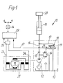
- FIG. 1 shows an electrohydraulic device 10 for speed control of a hydraulic Lift cylinder 11, which here as a single-acting Working cylinder is designed as it is in hoists for Lifting and lowering loads, especially in forklifts, is used.
- the device 10 has a hydraulic Constant pump 12, the pressure medium from a tank 13 sucks and the pressure side with a working line 14 the lifting cylinder 11 is connected.
- a load securing the lifting cylinder 11 Check valve 15 switched.
- the print page via a pressure relief valve 16 hydraulically secured.
- the Proportional throttle valve 18 is for securely shutting off the Lift cylinder 11 executed in the seat valve type and secures in a spring-centered starting position 19 the load on Lift cylinder 11 from.
- the constant pump 12 is mechanically driven by an electric motor 21 driven, here as a simple DC motor is executed.
- the electric motor 21 is one controlled electrical control device 22, wherein in the electrical connection to its two terminals 23 and 24 a current sensor 25 is connected.
- This current sensor 25 is designed in the simplest way as a measuring resistor, whereby the measured variable determined by him, namely that for Electric motor 21 flowing electricity to the electric Control device 22 is reported back.
- the electrical Control device 22 also stands with a setpoint adjuster 26 in connection with which a setpoint for the Speed of the lifting cylinder 11 when lifting and Lowering can be specified.
- the control signals in the form of electric currents for the proportional throttle valve 18 generated and corrected, which is why the control device 22nd via an electrical control line 27 with the magnetic drive 28 of the proportional throttle valve 18 is connected.
- the electrical control device 22 are the functions the energy supply, a controller, a computer and an electronic memory integrated, the Control device in a manner known per se in Microprocessor technology can be executed.
- connection therefore applies that the size of the electric current for driving the Electric motor 21 is proportional to the hydraulic Load pressure in the lifting cylinder 11.
- current to the electric motor 21 is supplied by the current sensor 25 measured in the simplest way as a measuring resistor can be executed.
- the actual value of the measured current is from the current sensor 25 to the electrical control device 22 returned so that this is a load-dependent variable receives.
- connection applies that the lifting speed of the load 29 results from one Product from a constant of the lifting cylinder 11 with the Volume flow lifting, this lifting speed of the load 29 also a function of the motor current in the current sensor 25 represents. It can therefore be used in electrical Control device 22 that measured by the current sensor 25 Current value with the lifting signal of the setpoint adjuster 26 be compared and according to the difference between them Signals from the control device 22 Proportional throttle valve 18 opened with a time delay with a part of the constant pump 12 volume flow flows back into the tank.
- the hydraulic connection of the device 10 results the size of the flowing into the lifting cylinder 11 Volume flow lifting as the difference from the volume flow of the Constant pump 12 minus the volume flow that over the Proportional throttle valve 18 flows out to the tank 13. Since the Volume flow of the constant pump 12 due to the constant Speed of the electric motor 21 is constant and the Volume flow via the throttle valve 18 is controllable also the size of the volume flow to the lifting cylinder 11 controllable. The size of the volume flow over the Throttle valve 18 is used by the electronic Control device 22 influenced so that the Setpoint adjuster 26 predetermined lifting setpoint proportional is to the speed of the load 29 in the lifting cylinder 11.
- connection applies that the lifting speed in Lift cylinder 11 proportional - but in the opposite sense - Is to the volume flow through the throttle valve 18 and also is proportional to the set Speed setpoint at setpoint adjuster 26. From the electrical control device 22 is ensured that the delivered volume flow of the constant pump 12 always is greater than that via the throttle valve 18 to the tank discharged volume flow.
- the in the electric DC motor 21st electrical energy plugged in is essentially the same is the hydraulic generated by the constant pump 12 Energy.
- the on the terminals 23, 24 of the electric motor 21 supply voltage is in the electrical Control device 22 before.
- the flowing to the electric motor 21 Current is measured by the current sensor 25 and this measured variable of the electrical control device 22 posed. From the available values for current and voltage on the electric motor 21, the electrical control device 22 determine the electrical power of the electric motor 21. This electrical power is converted into a hydraulic one Power implemented resulting from that of the constant pump delivered volume flow and the respective load pressure in Lifts 11 can be determined.
- the Current sensor 25 with its measured variable lifting current a signal for the electrical control device 22 is available, which at This device 10 is proportional to hydraulic load pressure in the lifting cylinder 11. Furthermore, in the electrical control device 22 pressure-dependent Characteristic curves of the proportional throttle valve 18 stored. With them, the electrical control device 22 can Control signals for the proportional throttle valve 18 so correct that overall an electronic Load compensation is possible. In the present electrohydraulic device 10 is thus created Control loop with a predetermined by the setpoint adjuster 26 Speed setpoint with which the current sensor 25 The measured quantity of the lifting current and the electrical one Voltage at the electric motor 21 as actual values for the Engine power and torque as well as with the Proportional throttle valve 18 as an actuator for the Lifting speed. With the setpoint adjuster 26 can thus in a load pressure compensated and proportional manner Lifting speed of the load 29 controlled on the lifting cylinder 11 become.
- the current sensor 25 Since in the electro-hydraulic device 10 of Electric motor 21 only works in the lifting operating state, while lowering with the electric motor 21 stopped the weight of the load 29 over the Proportional throttle valve 18 takes place, the current sensor 25 also no instantaneous measured variable for the current and thus the Load pressure available. In some cases it can now occur that the electronic load compensation at Lowering with the stored current value is not sufficient Accuracy results because the load 29 when lowering greatly from the Load deviates in the previous lifting, such as this for Example when setting down, picking up or changing pallets the case is.
- Figure 2 shows a second electrohydraulic Device 40 for speed control of a hydraulic lifting cylinder 11, which differs from the device 10 according to Figure 1 mainly differs in that the Structure of the electrical / electronic control device 22 is shown in more detail. Otherwise, the same components as in Figure 1 provided with the same reference numerals.
- the second device 40 has a current sensor simple measuring resistor 25 on the in the power supply is connected to the electric motor 21.
- the electrical energy is connected to a supply connection 41 with a Battery voltage supplied.
- a relay 42 is connected to the power supply.
- the size of the electrical current across the measuring resistor 25 tapped and fed to a current-voltage converter 43, whose output signal is smoothed by a filter 44 and whose output variable at a first input 45 of a first Computer 46 is present.
- the first computer 46 is started a second input 47 that is applied to the electric motor 21 Motor voltage supplied.
- At a third entrance 48 of the first computer 46 is the battery voltage from Supply connection 41 on.
- the first computer 46 takes place now a power calculation with the entered sizes Current and voltage instead, with the characteristics of Electric motor 21 is corrected. In particular, too takes into account its starting and stopping behavior, so that at the output 51 of the first computer 46 an essentially linearized actual value of the output is output.
- This Power signal at output 51 is now at a summation point 52 with a setpoint signal from setpoint adjuster 46 compared and the resulting difference signal one entered second computer 53 for the lifting function Adjustment calculates a correction value, and with this one first computing element 54 in the electrical lifting path of the Control device 22 controls.
- That from the setpoint adjuster 26 predetermined lifting signal is not just a measure of the required performance, but as a result of the present here Connections also measure the speed at the same time the load 29 in the lifting cylinder 11.
- This lifting signal is now in the first computing element 54 as a function of that in the second Computer 53 determined correction value and corrected a lift switch 55 to an electric current regulator 56 performed, the with a proportional signal Solenoid actuator 28 controls the proportional throttle valve 18.
- the current regulator 56 is used for this purpose Supply terminal 41 forth with the battery voltage acted upon.
- the first computing element 54 contains the Proportional throttle valve 18 assigned characteristic curves 57 for different pressures are saved, with the help of which Control signal for the proportional throttle valve 18 so Corrected that overall an electronic Load compensation when lifting the load 29 is controllable.
- the release of the Lift function controls and its output signal the relay 42 controls to turn on the electric motor 21.
- the set point adjuster 26 in opposite direction and this Setpoint signal in the same way as in the lifting path a second computing element 61, in which a Calculation and correction of the sink current to control the Proportional throttle valve 18 takes place.
- the third computer becomes 64 from a sample and hold 65 with a memory signal driven, the sample and hold member 65 from the first Threshold switch 58 can be activated. That way realized a common sample and hold circuit, so that the last one available when the lifting function was switched off Last value saved and for subsequent Sink correction can be used.
- overload protection can be used in the second Realize device 40 so that on an additional hydraulic pressure relief valve to protect the Constant pump can be dispensed with.
- the operation of the second device 40 is the same largely that of the first facility 10.
- the second device 40 will now turn on and off Electric motor 21 controlled by a relay 42, because the Motor currents can assume considerable sizes.
- the by Switching of the relay 42 caused delayed hydraulic Pressure build-up takes into account that one on the Lifting path 54, 55 acting delay element 59 for a corresponding delay in the activation of the Proportional throttle valve 18 ensures that no pressure drop can arise in the lifting cylinder 11.
- the relay 42 and an overload switch 66 on simple Way to build an overload protection.
- the speed of the load 29 being proportional is the size of the setpoint signals at setpoint adjuster 26.
- the means for the methods with an additional measuring stroke are not in the case of the electrical control device 22 in FIG. 2 specified; but you can always in the second device 40 can be added.
Landscapes
- Engineering & Computer Science (AREA)
- Physics & Mathematics (AREA)
- Fluid Mechanics (AREA)
- Mechanical Engineering (AREA)
- General Engineering & Computer Science (AREA)
- Chemical & Material Sciences (AREA)
- Analytical Chemistry (AREA)
- Fluid-Pressure Circuits (AREA)
Abstract
Description
Claims (14)
- Elektrohydraulische Einrichtung zur Geschwindigkeitssteuerung eines hydraulischen Hubzylinders, der beim Heben von einer Konstantpumpe über eine Arbeitsleitung mit einem den Hubzylinder absichernden Rückschlagventil mit Druckmittel beaufschlagbar ist und der wenigstens beim Senken über ein Proportionaldrosselventil in Sitzventilbauart zum Tank entlastbar ist, wobei das Proportionaldrosselventil und ein die Konstantpumpe antreibender Elektromotor von einer elektrischen Steuereinrichtung ansteuerbar sind, die mit einem Sollwertsteller zur Vorgabe des Geschwindigkeitssollwertes in Verbindung steht und daß Mittel vorgesehen sind, die ein lastdruckunabhängiges Heben und Senken des Hubzylinders ermöglichen, dadurch gekennzeichnet, daß die Einrichtung (10, 40) ein einziges Proportionalventil (18) aufweist, das in eine vom Hubzylinder (11) zum Tank (13) geführte Bypaßleitung (17) geschaltet ist und daß die Mittel einen den elektrischen Strom zum Elektromotor (21) messenden Stromsensor (25) aufweisen, dessen vom Lastdruck im Hubzylinder (11) abhängige Signale von der elektrischen Steuereinrichtung (22) für die Ansteuerung des Proportionalventils(18)verarbeitet werden, um eine lastdruckkompensierte Steuerung des Hubzylinders (11) zu ermöglichen.
- Elektrohydraulische Einrichtung nach Anspruch 1, dadurch gekennzeichnet, daß der Stromsensor ein einfacher Meßwiderstand (25) ist, der in die elektrische Zuleitung zum Elektromotor (21) geschaltet ist.
- Elektrohydraulische Einrichtung nach den Ansprüchen 1 oder 2, dadurch gekennzeichnet, daß als Elektromotor ein Gleichstrommotor(21)verwendet wird.
- Elektrohydraulische Einrichtung nach einem der Ansprüche 1 bis 3, dadurch gekennzeichnet, daß ein von der elektrischen Steuereinrichtung (22) ansteuerbares Relais (42) angeordnet ist, mit dem die Stromversorgung des Elektromotors (21) ein- und ausschaltbar ist.
- Elektrohydraulische Einrichtung nach Anspruch 4, dadurch gekennzeichnet, daß die elektrische Steuereinrichtung (22) aus den Signalen des Stromsensors (25) und der Betriebsspannung am Elektromotor (21) dessen Belastung ermittelt und bei dessen Überlastung mittels eines ÜberlastSchalters (66) das Relais (42) betätigt.
- Elektrohydraulische Einrichtung nach Anspruch 4 oder 5, dadurch gekennzeichnet, daß das elektrische Steuergerät (22) ein auf den Hebenpfad (54, 55) einwirkendes Verzögerungsglied (59) aufweist, das die Ansteuerung des Proportionaldrosselventils (18) so weit verzögert, daß der mit dem Schalten des Relais (42) verbundene, verzögerte Aufbau des hydraulischen Drucks kompensiert wird.
- Elektrohydraulische Einrichtung nach einem der Ansprüche 1 bis 6, dadurch gekennzeichnet, daß die Bypaßleitung (17) stromabwärts von dem den Hubzylinder (11) absichernden Rückschlagventil (15) von der Arbeitsleitung(14) abzweigt.
- Elektrohydraulische Einrichtung nach einem oder mehreren der Ansprüche 1 bis 7, dadurch gekennzeichnet, daß die elektrische Steuereinrichtung (22) aus den gemessenen Signalen für Strom und Spannung am Elektromotor (21) einen Istwert für die Leistung bzw. die Hubgeschwindigkeit der Last (29) ermittelt, der mit einem entsprechenden Sollwert vom Sollwertsteller (26) verglichen wird und daß das daraus gebildete Differenzsignal für die Korrektur des Hebenstromes zur Ansteuerung des Proportionalventils (18) verwendet wird.
- Elektrohydraulische Einrichtung nach Anspruch 8, dadurch gekennzeichnet, daß die elektrische Steuereinrichtung (22) für die Ermittlung von Hebenstrom und Senkenstrom jeweils gesonderte Rechenglieder (54, 61) aufweist, in denen insbesondere dem Proportionaldrosselventil (18) zugeordnete Druckkennlinien (57) abgespeichert sind.
- Elektrohydraulische Einrichtung nach einem der Ansprüche 1 bis 9, dadurch gekennzeichnet, daß die elektrische Steuereinrichtung (22) ein Abtasthalteglied (65, 64) aufweist, das ein lastabhängiges Signal aus dem Hebenvorgang speichert und für die Korrektur des Senkenstromes zum Ansteuern des Proportionaldrosselventil (18) zur Verfügung stellt.
- Verfahren zur Geschwindigkeitssteuerung eines hydraulischen Hubzylinders mit einer elektrohydraulischen Einrichtung nach einem der Ansprüche 1 bis 10, dadurch gekennzeichnet, daß die Konstantpumpe (12) von dem Elektromotor (21) mit konstanter Drehzahl angetrieben wird und beim Heben des Hubzylinders (11) ein Teil des von der Konstantpumpe geförderten Volumenstroms vom Proportionaldrosselventil (18) zum Tank (13) abführbar ist, während beim Senken die Konstantpumpe (12) abgeschaltet ist und der vom Hubzylinder (11) zum Tank (13) abfließende Druckmittelstrom von dem Proportionaldrosselventil (18) steuerbar ist, wobei die elektrische Steuereinrichtung (22) in beiden Fällen das Proportionaldrosselventil (18) derart steuert, daß eine Lastdruckkompensation erfolgt.
- Verfahren nach Anspruch 11, dadurch gekennzeichnet, daß vor dem Beginn eines Senkenvorganges des Hubzylinders (11) ein kurzer Meßhub in Richtung Heben durchgeführt wird und daß hierbei ein vom Stromsensor (25) ermitteltes, lastabhängiges Signal für die Korrektur des Ansteuersignals am Proportionaldrosselventil (18) beim Senkenvorgang verwendet wird.
- Verfahren nach Anspruch 12, dadurch gekennzeichnet, daß zur Verringerung der Größe des Meßhubes das Proportionaldrosselventil (18) während des Meßhubes gleichzeitig in Öffnungsrichtung betätigt wird.
- Verfahren nach Anspruch 13, dadurch gekennzeichnet, daß das Proportionaldrosselventil (18) während des Meßhubes gleichzeitig mit dem Einschalten des Elektromotors (21) betätigt und sein Steuerglied einen definierten, geringen Öffnungshub ausführt.
Applications Claiming Priority (2)
| Application Number | Priority Date | Filing Date | Title |
|---|---|---|---|
| DE19844795 | 1998-09-30 | ||
| DE19844795A DE19844795A1 (de) | 1998-09-30 | 1998-09-30 | Elektrohydraulische Einrichtung zur Geschwindigkeitssteuerung eines hydraulischen Hubzylinders |
Publications (3)
| Publication Number | Publication Date |
|---|---|
| EP0990802A2 true EP0990802A2 (de) | 2000-04-05 |
| EP0990802A3 EP0990802A3 (de) | 2001-07-25 |
| EP0990802B1 EP0990802B1 (de) | 2004-10-13 |
Family
ID=7882758
Family Applications (1)
| Application Number | Title | Priority Date | Filing Date |
|---|---|---|---|
| EP99114323A Expired - Lifetime EP0990802B1 (de) | 1998-09-30 | 1999-07-21 | Elektrohydraulische Einrichtung zur Geschwindigkeitssteuerung eines hydraulischen Hubzylinders |
Country Status (2)
| Country | Link |
|---|---|
| EP (1) | EP0990802B1 (de) |
| DE (2) | DE19844795A1 (de) |
Cited By (7)
| Publication number | Priority date | Publication date | Assignee | Title |
|---|---|---|---|---|
| EP3336050A1 (de) * | 2016-12-15 | 2018-06-20 | Jungheinrich Aktiengesellschaft | Flurförderzeug mit einer steuereinheit zur regelung der bewegung einer kolbenstange eines hydraulikzylinders sowie ein solches verfahren |
| CN109139577A (zh) * | 2017-06-27 | 2019-01-04 | 罗伯特·博世有限公司 | 阀块装置和用于阀块装置的方法 |
| CN110131251A (zh) * | 2019-01-09 | 2019-08-16 | 哈尔滨工业大学 | 电液复合伺服加载方法及装置 |
| US10850958B2 (en) | 2016-12-06 | 2020-12-01 | Jungheinrich Aktiengesellschaft | Method for automatically aligning an industrial truck in a warehouse, and system comprising an industrial truck and a warehouse |
| WO2021004657A1 (en) * | 2019-07-08 | 2021-01-14 | Eaton Intelligent Power Limited | Hydraulic system architectures and bidirectional proportional valves usable in the system architectures |
| CN113757197A (zh) * | 2021-07-22 | 2021-12-07 | 浙江大学 | 一种泵站的恒压控制方法 |
| CN113757196A (zh) * | 2021-07-22 | 2021-12-07 | 浙江大学 | 一种长距离供液恒压控制方法 |
Families Citing this family (5)
| Publication number | Priority date | Publication date | Assignee | Title |
|---|---|---|---|---|
| DE102004057878B4 (de) * | 2003-12-08 | 2014-01-23 | Continental Teves Ag & Co. Ohg | Verfahren zur Kalibrierung von analog angesteuerten hydraulischen Ventilen |
| DE102010005146A1 (de) * | 2010-01-19 | 2011-07-21 | KONECRANES Lifting Systems GmbH, 40789 | Fahrbare Transport-und Handhabungseinrichtung mit Luftkissenanordnung und Steuerung |
| US8844280B2 (en) | 2011-02-28 | 2014-09-30 | Caterpillar Inc. | Hydraulic control system having cylinder flow correction |
| DE102016122379B4 (de) * | 2016-11-21 | 2022-12-15 | Magna Pt B.V. & Co. Kg | Hydraulikventil-Umschaltpunkterfassungsverfahren sowie Steuergerät für einen Kraftfahrzeugantriebstrang |
| DE102022116888B3 (de) | 2022-07-06 | 2023-12-14 | Ringspann Gmbh | Elektrohydraulische Bremslüftvorrichtung und Bremsvorrichtung |
Citations (2)
| Publication number | Priority date | Publication date | Assignee | Title |
|---|---|---|---|---|
| DE4140409A1 (de) | 1991-12-07 | 1993-06-09 | Robert Bosch Gmbh, 7000 Stuttgart, De | Elektrohydraulische steuereinrichtung |
| DE19631804A1 (de) | 1996-07-10 | 1998-01-15 | Rexroth Mannesmann Gmbh | Hydraulische Hubeinrichtung |
Family Cites Families (2)
| Publication number | Priority date | Publication date | Assignee | Title |
|---|---|---|---|---|
| DE3602510A1 (de) * | 1986-01-28 | 1987-07-30 | Steinbock Gmbh | Hydraulisches hubwerk |
| JP3220637B2 (ja) * | 1996-03-21 | 2001-10-22 | 日興電機工業株式会社 | 油圧パワーユニット装置 |
-
1998
- 1998-09-30 DE DE19844795A patent/DE19844795A1/de not_active Withdrawn
-
1999
- 1999-07-21 EP EP99114323A patent/EP0990802B1/de not_active Expired - Lifetime
- 1999-07-21 DE DE1999510818 patent/DE59910818D1/de not_active Expired - Fee Related
Patent Citations (2)
| Publication number | Priority date | Publication date | Assignee | Title |
|---|---|---|---|---|
| DE4140409A1 (de) | 1991-12-07 | 1993-06-09 | Robert Bosch Gmbh, 7000 Stuttgart, De | Elektrohydraulische steuereinrichtung |
| DE19631804A1 (de) | 1996-07-10 | 1998-01-15 | Rexroth Mannesmann Gmbh | Hydraulische Hubeinrichtung |
Cited By (9)
| Publication number | Priority date | Publication date | Assignee | Title |
|---|---|---|---|---|
| US10850958B2 (en) | 2016-12-06 | 2020-12-01 | Jungheinrich Aktiengesellschaft | Method for automatically aligning an industrial truck in a warehouse, and system comprising an industrial truck and a warehouse |
| EP3336050A1 (de) * | 2016-12-15 | 2018-06-20 | Jungheinrich Aktiengesellschaft | Flurförderzeug mit einer steuereinheit zur regelung der bewegung einer kolbenstange eines hydraulikzylinders sowie ein solches verfahren |
| CN109139577A (zh) * | 2017-06-27 | 2019-01-04 | 罗伯特·博世有限公司 | 阀块装置和用于阀块装置的方法 |
| CN109139577B (zh) * | 2017-06-27 | 2023-05-02 | 罗伯特·博世有限公司 | 阀块装置和用于阀块装置的方法 |
| CN110131251A (zh) * | 2019-01-09 | 2019-08-16 | 哈尔滨工业大学 | 电液复合伺服加载方法及装置 |
| WO2021004657A1 (en) * | 2019-07-08 | 2021-01-14 | Eaton Intelligent Power Limited | Hydraulic system architectures and bidirectional proportional valves usable in the system architectures |
| CN113757197A (zh) * | 2021-07-22 | 2021-12-07 | 浙江大学 | 一种泵站的恒压控制方法 |
| CN113757196A (zh) * | 2021-07-22 | 2021-12-07 | 浙江大学 | 一种长距离供液恒压控制方法 |
| CN113757197B (zh) * | 2021-07-22 | 2023-02-14 | 浙江大学 | 一种泵站的恒压控制方法 |
Also Published As
| Publication number | Publication date |
|---|---|
| DE59910818D1 (de) | 2004-11-18 |
| DE19844795A1 (de) | 2000-04-13 |
| EP0990802B1 (de) | 2004-10-13 |
| EP0990802A3 (de) | 2001-07-25 |
Similar Documents
| Publication | Publication Date | Title |
|---|---|---|
| DE3602510C2 (de) | ||
| DE2745937C2 (de) | Hydraulikkreis insbesondere für einen Gabelstapler | |
| DE19654427B4 (de) | Verfahren und Vorrichtung zur Regelung des Drucks in wenigstens einer Radbremse | |
| DE4402653C2 (de) | Hydraulische Hubvorrichtung für batteriebetriebene Flurförderzeuge | |
| EP0990802B1 (de) | Elektrohydraulische Einrichtung zur Geschwindigkeitssteuerung eines hydraulischen Hubzylinders | |
| DE4037142A1 (de) | Elektromotorisch betriebene hydropumpe | |
| DE10319484A1 (de) | Hydrauliksteuersystem | |
| EP0546300A1 (de) | Elektrohydraulische Steuereinrichtung | |
| DE10010670C2 (de) | Hydraulische Hubvorrichtung für batteriebetriebene Flurförderzeuge | |
| DE3218077A1 (de) | Elektromechanische steuerung fuer hydraulische aufzuege | |
| EP3336051A1 (de) | Hubvorrichtung für ein flurförderzeug sowie ein solches flurförderzeug | |
| DE69706208T2 (de) | Servolenkung | |
| DE4140408A1 (de) | Elektrohydraulische steuereinrichtung | |
| EP0502411A2 (de) | Hydrauliksystem zur Steuerung einer einen Verbraucher bewegenden Kraft | |
| EP0275969B1 (de) | Steuervorrichtung fuer ein hydrostatisches Getriebe fuer wenigstens zwei Verbraucher | |
| EP0251290B1 (de) | Kraftfahrzeug, vorzugsweise Flurförderzeug, mit einer hydraulischen Arbeitseinrichtung und mit einer hydraulischen Lenkhilfskraftunterstützungseinrichtung | |
| DE3629089C3 (de) | Hubstapler, insbesondere industrieller Hubstapler, mit Hubmast | |
| DE9415062U1 (de) | Hydraulische Hubvorrichtung für batteriebetriebene Flurförderzeuge o.dgl. | |
| DE1673601A1 (de) | Regelverfahren fuer traegheitsbehaftete Regelstrecken | |
| EP1067296B1 (de) | Elektrohydraulischer Hubmodul | |
| DE3911706A1 (de) | Verfahren zum betreiben einer antriebseinheit | |
| EP0797727A1 (de) | Hydraulikanlage fur ein kraftfahrzeug | |
| DE3013853A1 (de) | Hydraulikanlage, insbesondere fuer kraftfahrzeuge | |
| DE69903623T2 (de) | Brennstoffzuführung zu einem brennerelement | |
| DE102011088976A1 (de) | Anordnung zur Ansteuerung einer elektrischen Vakuum-Pumpe |
Legal Events
| Date | Code | Title | Description |
|---|---|---|---|
| PUAI | Public reference made under article 153(3) epc to a published international application that has entered the european phase |
Free format text: ORIGINAL CODE: 0009012 |
|
| AK | Designated contracting states |
Kind code of ref document: A2 Designated state(s): DE FR GB IT SE |
|
| AX | Request for extension of the european patent |
Free format text: AL;LT;LV;MK;RO;SI |
|
| PUAL | Search report despatched |
Free format text: ORIGINAL CODE: 0009013 |
|
| AK | Designated contracting states |
Kind code of ref document: A3 Designated state(s): AT BE CH CY DE DK ES FI FR GB GR IE IT LI LU MC NL PT SE |
|
| AX | Request for extension of the european patent |
Free format text: AL;LT;LV;MK;RO;SI |
|
| 17P | Request for examination filed |
Effective date: 20020125 |
|
| AKX | Designation fees paid |
Free format text: DE FR GB IT SE |
|
| GRAP | Despatch of communication of intention to grant a patent |
Free format text: ORIGINAL CODE: EPIDOSNIGR1 |
|
| GRAS | Grant fee paid |
Free format text: ORIGINAL CODE: EPIDOSNIGR3 |
|
| GRAA | (expected) grant |
Free format text: ORIGINAL CODE: 0009210 |
|
| AK | Designated contracting states |
Kind code of ref document: B1 Designated state(s): DE FR GB IT SE |
|
| PG25 | Lapsed in a contracting state [announced via postgrant information from national office to epo] |
Ref country code: IT Free format text: LAPSE BECAUSE OF FAILURE TO SUBMIT A TRANSLATION OF THE DESCRIPTION OR TO PAY THE FEE WITHIN THE PRE;WARNING: LAPSES OF ITALIAN PATENTS WITH EFFECTIVE DATE BEFORE 2007 MAY HAVE OCCURRED AT ANY TIME BEFORE 2007. THE CORRECT EFFECTIVE DATE MAY BE DIFFERENT FROM THE ONE RECORDED.SCRIBED TIME-LIMIT Effective date: 20041013 |
|
| REG | Reference to a national code |
Ref country code: GB Ref legal event code: FG4D Free format text: NOT ENGLISH |
|
| REF | Corresponds to: |
Ref document number: 59910818 Country of ref document: DE Date of ref document: 20041118 Kind code of ref document: P |
|
| PG25 | Lapsed in a contracting state [announced via postgrant information from national office to epo] |
Ref country code: SE Free format text: LAPSE BECAUSE OF FAILURE TO SUBMIT A TRANSLATION OF THE DESCRIPTION OR TO PAY THE FEE WITHIN THE PRESCRIBED TIME-LIMIT Effective date: 20050113 |
|
| GBT | Gb: translation of ep patent filed (gb section 77(6)(a)/1977) |
Effective date: 20050131 |
|
| ET | Fr: translation filed | ||
| PLBE | No opposition filed within time limit |
Free format text: ORIGINAL CODE: 0009261 |
|
| STAA | Information on the status of an ep patent application or granted ep patent |
Free format text: STATUS: NO OPPOSITION FILED WITHIN TIME LIMIT |
|
| 26N | No opposition filed |
Effective date: 20050714 |
|
| PGFP | Annual fee paid to national office [announced via postgrant information from national office to epo] |
Ref country code: DE Payment date: 20090918 Year of fee payment: 11 |
|
| PGFP | Annual fee paid to national office [announced via postgrant information from national office to epo] |
Ref country code: FR Payment date: 20100802 Year of fee payment: 12 |
|
| PGFP | Annual fee paid to national office [announced via postgrant information from national office to epo] |
Ref country code: GB Payment date: 20100726 Year of fee payment: 12 |
|
| PG25 | Lapsed in a contracting state [announced via postgrant information from national office to epo] |
Ref country code: DE Free format text: LAPSE BECAUSE OF NON-PAYMENT OF DUE FEES Effective date: 20110201 |
|
| REG | Reference to a national code |
Ref country code: DE Ref legal event code: R119 Ref document number: 59910818 Country of ref document: DE Effective date: 20110201 |
|
| GBPC | Gb: european patent ceased through non-payment of renewal fee |
Effective date: 20110721 |
|
| REG | Reference to a national code |
Ref country code: FR Ref legal event code: ST Effective date: 20120330 |
|
| PG25 | Lapsed in a contracting state [announced via postgrant information from national office to epo] |
Ref country code: FR Free format text: LAPSE BECAUSE OF NON-PAYMENT OF DUE FEES Effective date: 20110801 |
|
| PG25 | Lapsed in a contracting state [announced via postgrant information from national office to epo] |
Ref country code: GB Free format text: LAPSE BECAUSE OF NON-PAYMENT OF DUE FEES Effective date: 20110721 |