EP0990859A2 - Dispositif d'amenée et évacuation d'air - Google Patents
Dispositif d'amenée et évacuation d'air Download PDFInfo
- Publication number
- EP0990859A2 EP0990859A2 EP99114412A EP99114412A EP0990859A2 EP 0990859 A2 EP0990859 A2 EP 0990859A2 EP 99114412 A EP99114412 A EP 99114412A EP 99114412 A EP99114412 A EP 99114412A EP 0990859 A2 EP0990859 A2 EP 0990859A2
- Authority
- EP
- European Patent Office
- Prior art keywords
- ventilation
- housing
- sound
- ventilation system
- impeller
- Prior art date
- Legal status (The legal status is an assumption and is not a legal conclusion. Google has not performed a legal analysis and makes no representation as to the accuracy of the status listed.)
- Withdrawn
Links
- 238000009423 ventilation Methods 0.000 claims abstract description 131
- 239000011358 absorbing material Substances 0.000 claims abstract description 6
- 238000005338 heat storage Methods 0.000 claims description 27
- 239000000463 material Substances 0.000 claims description 14
- 238000011084 recovery Methods 0.000 abstract description 6
- 238000005253 cladding Methods 0.000 abstract 2
- 230000002349 favourable effect Effects 0.000 description 4
- 229910052751 metal Inorganic materials 0.000 description 4
- 239000006096 absorbing agent Substances 0.000 description 3
- 238000009434 installation Methods 0.000 description 3
- 239000002184 metal Substances 0.000 description 3
- 230000002787 reinforcement Effects 0.000 description 3
- 238000010521 absorption reaction Methods 0.000 description 2
- 238000010276 construction Methods 0.000 description 2
- 238000010438 heat treatment Methods 0.000 description 2
- 239000010410 layer Substances 0.000 description 2
- 150000002739 metals Chemical class 0.000 description 2
- 230000000149 penetrating effect Effects 0.000 description 2
- 239000011241 protective layer Substances 0.000 description 2
- 238000013022 venting Methods 0.000 description 2
- 238000005273 aeration Methods 0.000 description 1
- 239000004020 conductor Substances 0.000 description 1
- 238000011161 development Methods 0.000 description 1
- 230000018109 developmental process Effects 0.000 description 1
- 238000010586 diagram Methods 0.000 description 1
- 230000000694 effects Effects 0.000 description 1
- 230000007613 environmental effect Effects 0.000 description 1
- 239000002657 fibrous material Substances 0.000 description 1
- 239000006260 foam Substances 0.000 description 1
- 238000012986 modification Methods 0.000 description 1
- 230000004048 modification Effects 0.000 description 1
- 239000003973 paint Substances 0.000 description 1
- 239000004033 plastic Substances 0.000 description 1
- 229920003023 plastic Polymers 0.000 description 1
- 239000011148 porous material Substances 0.000 description 1
- 230000002265 prevention Effects 0.000 description 1
- 230000001105 regulatory effect Effects 0.000 description 1
- 238000009420 retrofitting Methods 0.000 description 1
Images

Classifications
-
- F—MECHANICAL ENGINEERING; LIGHTING; HEATING; WEAPONS; BLASTING
- F24—HEATING; RANGES; VENTILATING
- F24F—AIR-CONDITIONING; AIR-HUMIDIFICATION; VENTILATION; USE OF AIR CURRENTS FOR SCREENING
- F24F13/00—Details common to, or for air-conditioning, air-humidification, ventilation or use of air currents for screening
- F24F13/24—Means for preventing or suppressing noise
-
- F—MECHANICAL ENGINEERING; LIGHTING; HEATING; WEAPONS; BLASTING
- F24—HEATING; RANGES; VENTILATING
- F24F—AIR-CONDITIONING; AIR-HUMIDIFICATION; VENTILATION; USE OF AIR CURRENTS FOR SCREENING
- F24F3/00—Air-conditioning systems in which conditioned primary air is supplied from one or more central stations to distributing units in the rooms or spaces where it may receive secondary treatment; Apparatus specially designed for such systems
- F24F3/12—Air-conditioning systems in which conditioned primary air is supplied from one or more central stations to distributing units in the rooms or spaces where it may receive secondary treatment; Apparatus specially designed for such systems characterised by the treatment of the air otherwise than by heating and cooling
- F24F3/14—Air-conditioning systems in which conditioned primary air is supplied from one or more central stations to distributing units in the rooms or spaces where it may receive secondary treatment; Apparatus specially designed for such systems characterised by the treatment of the air otherwise than by heating and cooling by humidification; by dehumidification
- F24F3/147—Air-conditioning systems in which conditioned primary air is supplied from one or more central stations to distributing units in the rooms or spaces where it may receive secondary treatment; Apparatus specially designed for such systems characterised by the treatment of the air otherwise than by heating and cooling by humidification; by dehumidification with both heat and humidity transfer between supplied and exhausted air
-
- F—MECHANICAL ENGINEERING; LIGHTING; HEATING; WEAPONS; BLASTING
- F24—HEATING; RANGES; VENTILATING
- F24F—AIR-CONDITIONING; AIR-HUMIDIFICATION; VENTILATION; USE OF AIR CURRENTS FOR SCREENING
- F24F5/00—Air-conditioning systems or apparatus not covered by F24F1/00 or F24F3/00, e.g. using solar heat or combined with household units such as an oven or water heater
- F24F5/0007—Air-conditioning systems or apparatus not covered by F24F1/00 or F24F3/00, e.g. using solar heat or combined with household units such as an oven or water heater cooling apparatus specially adapted for use in air-conditioning
- F24F5/0017—Air-conditioning systems or apparatus not covered by F24F1/00 or F24F3/00, e.g. using solar heat or combined with household units such as an oven or water heater cooling apparatus specially adapted for use in air-conditioning using cold storage bodies, e.g. ice
-
- F—MECHANICAL ENGINEERING; LIGHTING; HEATING; WEAPONS; BLASTING
- F24—HEATING; RANGES; VENTILATING
- F24F—AIR-CONDITIONING; AIR-HUMIDIFICATION; VENTILATION; USE OF AIR CURRENTS FOR SCREENING
- F24F3/00—Air-conditioning systems in which conditioned primary air is supplied from one or more central stations to distributing units in the rooms or spaces where it may receive secondary treatment; Apparatus specially designed for such systems
- F24F3/12—Air-conditioning systems in which conditioned primary air is supplied from one or more central stations to distributing units in the rooms or spaces where it may receive secondary treatment; Apparatus specially designed for such systems characterised by the treatment of the air otherwise than by heating and cooling
- F24F3/14—Air-conditioning systems in which conditioned primary air is supplied from one or more central stations to distributing units in the rooms or spaces where it may receive secondary treatment; Apparatus specially designed for such systems characterised by the treatment of the air otherwise than by heating and cooling by humidification; by dehumidification
- F24F2003/1458—Air-conditioning systems in which conditioned primary air is supplied from one or more central stations to distributing units in the rooms or spaces where it may receive secondary treatment; Apparatus specially designed for such systems characterised by the treatment of the air otherwise than by heating and cooling by humidification; by dehumidification using regenerators
-
- Y—GENERAL TAGGING OF NEW TECHNOLOGICAL DEVELOPMENTS; GENERAL TAGGING OF CROSS-SECTIONAL TECHNOLOGIES SPANNING OVER SEVERAL SECTIONS OF THE IPC; TECHNICAL SUBJECTS COVERED BY FORMER USPC CROSS-REFERENCE ART COLLECTIONS [XRACs] AND DIGESTS
- Y02—TECHNOLOGIES OR APPLICATIONS FOR MITIGATION OR ADAPTATION AGAINST CLIMATE CHANGE
- Y02E—REDUCTION OF GREENHOUSE GAS [GHG] EMISSIONS, RELATED TO ENERGY GENERATION, TRANSMISSION OR DISTRIBUTION
- Y02E60/00—Enabling technologies; Technologies with a potential or indirect contribution to GHG emissions mitigation
- Y02E60/14—Thermal energy storage
Definitions
- the invention relates to a ventilation and ventilation system, especially with heat storage elements, the Ventilation and ventilation system at least one housing and has at least one air conveyor.
- DE 41 04 423 C2 and DE 36 13 942 A1 also describe similar ventilation and ventilation systems that also with heat storage elements for heat recovery are equipped.
- Ventilation and ventilation systems are also generally known without heat storage elements, as preferred for Toilet rooms or as pure exhaust air systems also for kitchen rooms be used.
- the ventilation and ventilation system also produces due to flow and drive noises even sound waves. together with the sound waves of the outside area this leads to a sometimes considerable noise pollution in the Lead interior. Under certain circumstances, this can be done with the penetrating an open or slanted window Soundscape to be comparable.
- This type of installation of a ventilation and ventilation system can only be used together with a new installation realize and have a corresponding roller shutter box not the acoustic results that differ from one to hope for such a construction.
- microperforated absorber MCA
- These micro-perforated absorbers are in able to reduce the effective flow resistance the undesirable acoustic effects in the perforation to relocate yourself. This can be a sound absorption can be realized which do not have open-pore foams, Fiber materials or the like are required.
- a ventilation and Ventilation system in particular with heat storage elements, to create with the least possible sound in the ventilated interior.
- this object is achieved in that the Housing at least one acoustically with the interior of the Has housing connected housing element, wherein the housing element entirely or at least approximately its largest Part made of a material with sound absorbing properties consists.
- a housing element of the housing Ventilation and ventilation system made of sound-absorbing Material are advantageously both the outside penetrating sound waves, as well as those caused by flow and Drive noises in the ventilation and ventilation system self-generated sound waves are largely absorbed. All that needs to be done is to ensure that the Sound waves through an acoustic connection, e.g. by Openings to the housing element with sound absorbing Properties can reach.
- the ventilation and The ventilation system can have a cylindrical design.
- round wall openings can be made easier to realize, so that such a cylindrical
- the design of the ventilation and ventilation system is ideal suitable for retrofitting old buildings, on the other hand result energetic advantages in the embodiment with Heat storage elements.
- the heat storage elements are common mostly designed as rib-shaped metal elements and can only be in the flow directly from an air stream Areas work. Because the air conveyor generally a round, axially acting impeller has only an annular area of the Heat storage elements flow from the conveyed air.
- the round construction of the ventilation system saves space, material and points through the Saving unused area of the heat storage elements energetic advantages.
- system can also have a centrally arranged casing, which is the drive unit of the air conveyor encloses on the outside a material with sound absorbing Have properties.
- a sound-absorbing material can be used to design a ventilation and ventilation system that reduces the noise level further reduced in the interior ventilated with it.
- Elements serve directly as micro-perforated absorbers, whereby both plastics and metals or the like as material for the case and at least the surfaces of the in elements contained in the housing and the housing interior can be used.
- the sound guide elements which in a particularly favorable embodiment at the same time can be provided as heat storage elements the use of microperforated metals or comparable good heat-conducting materials conceivable.
- Fig. 1 is a cross section through the ventilation and Ventilation system 1 recognizable.
- the ventilation and ventilation system 1 has an air delivery device 3 with a round, axially acting impeller 4 on.
- the heat storage elements 2 are in 1 only indicated by its principally possible location, where they are executed in any geometrical form can. However, are radially arranged ribs or Spiral parts (not shown) as heat storage elements 2 particularly cheap because they are capable are also to serve as sound guide elements and the Derive sound waves both outside and inside.
- an outer housing 5 of the ventilation system 1 consists of several parts, the The innermost part is an inner housing 5 with numerous openings 7 is.
- the inner housing 6 as a perforated sheet-like part or in the form of a lattice structure be executed.
- a sound-absorbing element is connected to the inner housing 6 on the outside Housing element 8.
- the openings 7 in the inner housing 6 serve as an acoustic connection of the inner area, which the housing 5 partially encloses the housing element 8.
- the outer surface 9 of the sound absorbing housing member 8 can be made from a directly on the outer surface 9 applied protective layer, e.g. a layer of paint, or from a thin housing part 10 (in FIG. 3 shown) exist. It should be ensured that the protective layer applied to the outer surface 9 or the thin housing part 10 is sufficient great resistance to mechanical damage at the Assembly and against moisture and other environmental influences guaranteed.
- the ventilation and Ventilation system 1 Immediately following the outermost layer of the housing 5 surrounds the building wall (not shown) the ventilation and Ventilation system 1.
- the housing element 8 can be made of different materials sound-absorbing properties exist. Particularly good sound-absorbing mats on a after installation of the sound-absorbing housing element 8 11 special structures facing inwards exhibit. This applies to material with sound-absorbing properties generally known, enlarging the surface 11 Structures, so-called backdrops, help the sound to absorb.
- the ventilation and ventilation system 1 with an outer Housing part 10 it is also conceivable in the space between inner housing 6 and outer housing part 10 sound absorbing bulk goods, e.g. Fill in flakes etc., which then the sound absorbing housing element 8 forms. In this particular case it would be more ideal Way to choose a lattice structure for the inner housing 6.
- the air delivery device 3 is located inside the housing 5 recognizable with the impeller 4 indicated in principle, what air in the axial direction through the ventilation and Ventilation system 1 promotes.
- Air conveyor 3 conceivable, especially those with separate impellers 4, one for ventilation and one other for ventilation.
- impellers 4 which with a direction of flow in one area of their wings than realizing with another area of their wings can be used.
- the invention can also be used in ventilation and ventilation systems 1 with a so-called recuperative heat exchanger, e.g. a cross-flow heat exchanger can be used.
- This Heat exchangers are characterized in that the air flow in one direction through the heat storage elements 2 is separated from the air flow in the other direction.
- a drive unit 15 of the air conveyor 3 is at the illustrated cylindrical embodiment of the ventilation system 1 centrally in the area of Axis of rotation 14 of the impeller 4 attached.
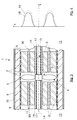
- Fig. 4 are in a path (s) -speed (v) diagram two different flow profiles are shown.
- the dotted Line shows a flow profile 16 as shown by the axially conveying impeller 4 is generated without a Influenced by housing elements etc. Clear it can be seen that in the area of the centrally arranged Drive unit 15 only low flow speed prevails. One can be energetic in this area Losses one through the at least approximate total ventilation and.
- the flow profile 14 shown is approximately at a system according to FIGS. 1 and 2.
- a sleeve 19 can be placed around the sleeve in a particularly favorable manner 17 entirely or at least for the most part made of a material with sound absorbing properties consist. This is in the ventilation and ventilation system 1 additional sound-absorbing surface created. In case of stability or material properties of the sound absorbing material this is necessary can make the shell 19 with a lattice structure or a perforated sheet-like part can be reinforced. By the appropriate choice of materials and arrangement of reinforcements, e.g. an outer skin with numerous holes around the shell 19, the reinforcements can also contribute to the Flow resistance inside the ventilation and ventilation system 1 lower.
- sheet metal fins which act as sound guiding elements and heat storage elements 2 serve radially arranged between the shell 19 and the inner housing 6 are in the ventilation and ventilation system 1 located sound waves ideal to the sound absorbing Cover 19 on the one hand and to the sound-absorbing housing element 8 derived on the other hand.
- Ventilation system 1 has such a cylindrical design sound-absorbing elements 20, in particular here Tubes 20, on. They are centered around the axis of rotation 14 of the Impeller 4 arranged, which is only a slight modification the heat storage elements 2 requires. should that sound absorbing material does not have the required mechanical Strength for the sound absorbing tubes 20 can have, analogously to the housing 5 and the casing 19 Lattice structures or perforated sheet-like parts for mechanical Reinforcement can be used.
- Embodiment can use the heat storage elements 2, which also serve as sound guide elements a micro-perforation known per se on their respective surface and thus absorb the external sound, which gets into the ventilation system 1.
- the heat storage elements 2 or the sound guide elements can also the outer skin of the shell 19 as well the outer surface 9 of the sound absorbing housing member 8 with the corresponding microperforation for absorption be provided with sound.
- the ventilation and ventilation system 1 at their inner space 12 or outer area 13 facing and not shown lateral ends elements customary there and known from the prior art, such as. Grids, filters, covers, etc., on.
Landscapes
- Engineering & Computer Science (AREA)
- Chemical & Material Sciences (AREA)
- Combustion & Propulsion (AREA)
- Mechanical Engineering (AREA)
- General Engineering & Computer Science (AREA)
- Life Sciences & Earth Sciences (AREA)
- Sustainable Development (AREA)
- Building Environments (AREA)
- Compressor (AREA)
Applications Claiming Priority (2)
| Application Number | Priority Date | Filing Date | Title |
|---|---|---|---|
| DE19844578 | 1998-09-29 | ||
| DE19844578A DE19844578A1 (de) | 1998-09-29 | 1998-09-29 | Belüftungs- und Entlüftungsanlage |
Publications (2)
| Publication Number | Publication Date |
|---|---|
| EP0990859A2 true EP0990859A2 (fr) | 2000-04-05 |
| EP0990859A3 EP0990859A3 (fr) | 2003-01-22 |
Family
ID=7882610
Family Applications (1)
| Application Number | Title | Priority Date | Filing Date |
|---|---|---|---|
| EP99114412A Withdrawn EP0990859A3 (fr) | 1998-09-29 | 1999-07-22 | Dispositif d'amenée et évacuation d'air |
Country Status (2)
| Country | Link |
|---|---|
| EP (1) | EP0990859A3 (fr) |
| DE (1) | DE19844578A1 (fr) |
Cited By (6)
| Publication number | Priority date | Publication date | Assignee | Title |
|---|---|---|---|---|
| EP2325573A2 (fr) | 2009-11-19 | 2011-05-25 | Poloplast GmbH & Co. KG | Dispositif d'aération et d'évacuation d'air pour un bâtiment |
| DE102012204865A1 (de) * | 2012-03-27 | 2013-10-02 | Öko-Haustechnik inVENTer GmbH | Belüftungsvorrichtung |
| CN106594955A (zh) * | 2016-12-13 | 2017-04-26 | 上海市建工设计研究院有限公司 | 预制装配钢结构住宅新风系统及其施工方法 |
| CN108386912A (zh) * | 2018-02-28 | 2018-08-10 | 肖石军 | 一种空调环境下的通风方法 |
| DE202017105511U1 (de) * | 2017-09-12 | 2018-12-14 | Heluvent Gmbh | Lüftungsvorrichtung |
| EP3569948A1 (fr) | 2018-05-17 | 2019-11-20 | InVENTer GmbH | Dispositif d'aération |
Families Citing this family (4)
| Publication number | Priority date | Publication date | Assignee | Title |
|---|---|---|---|---|
| DE202012007862U1 (de) | 2012-03-12 | 2012-09-20 | Peter Mader | Strömungskörper |
| EP3249313B1 (fr) * | 2013-09-06 | 2020-11-04 | Zehnder Group International AG | Silencieux pour unité de ventilation à récupération de chaleur |
| EP3222923A1 (fr) * | 2016-03-22 | 2017-09-27 | Marley Deutschland GmbH | Systeme d'aération à échangeur thermique |
| CN113028546B (zh) * | 2021-03-02 | 2024-12-06 | 徐州蓝湖信息科技有限公司 | 一种新风系统用过滤装置 |
Citations (4)
| Publication number | Priority date | Publication date | Assignee | Title |
|---|---|---|---|---|
| DE3613942A1 (de) | 1986-04-24 | 1987-10-29 | Erich Klawitter | Entlueftungs- und belueftungsanlage mit einem waermespeicher |
| DE4104423A1 (de) | 1991-02-14 | 1992-08-20 | Erich Klawitter | Entlueftungs- und belueftungsanlage mit einem waermespeicher |
| DE9301812U1 (de) | 1993-02-10 | 1993-05-13 | Diels, Manfred, 5882 Meinerzhagen | Entlüftungs- und Belüftungsanlage mit einem Wärmespeicher |
| DE29808237U1 (de) | 1998-05-07 | 1998-07-30 | GISOTON Baustoffwerke Gebhart & Söhne GmbH & Co., 88317 Aichstetten | Rolladenkasten für einen Rolladen |
Family Cites Families (3)
| Publication number | Priority date | Publication date | Assignee | Title |
|---|---|---|---|---|
| US5050667A (en) * | 1990-05-15 | 1991-09-24 | Erling Berner | Air ventilation and heat exchange apparatus |
| SE9303815L (sv) * | 1993-11-17 | 1995-05-18 | Hans Oestberg | Värmeåtervinningsaggregat för luftvärmeväxlingssystem |
| DE9400454U1 (de) * | 1994-01-13 | 1994-03-03 | Diels, Manfred, 58540 Meinerzhagen | Entlüftungs- und Belüftungsanlage |
-
1998
- 1998-09-29 DE DE19844578A patent/DE19844578A1/de not_active Withdrawn
-
1999
- 1999-07-22 EP EP99114412A patent/EP0990859A3/fr not_active Withdrawn
Patent Citations (4)
| Publication number | Priority date | Publication date | Assignee | Title |
|---|---|---|---|---|
| DE3613942A1 (de) | 1986-04-24 | 1987-10-29 | Erich Klawitter | Entlueftungs- und belueftungsanlage mit einem waermespeicher |
| DE4104423A1 (de) | 1991-02-14 | 1992-08-20 | Erich Klawitter | Entlueftungs- und belueftungsanlage mit einem waermespeicher |
| DE9301812U1 (de) | 1993-02-10 | 1993-05-13 | Diels, Manfred, 5882 Meinerzhagen | Entlüftungs- und Belüftungsanlage mit einem Wärmespeicher |
| DE29808237U1 (de) | 1998-05-07 | 1998-07-30 | GISOTON Baustoffwerke Gebhart & Söhne GmbH & Co., 88317 Aichstetten | Rolladenkasten für einen Rolladen |
Non-Patent Citations (1)
| Title |
|---|
| BAUPHYSIK, vol. 20, 1998 |
Cited By (6)
| Publication number | Priority date | Publication date | Assignee | Title |
|---|---|---|---|---|
| EP2325573A2 (fr) | 2009-11-19 | 2011-05-25 | Poloplast GmbH & Co. KG | Dispositif d'aération et d'évacuation d'air pour un bâtiment |
| DE102012204865A1 (de) * | 2012-03-27 | 2013-10-02 | Öko-Haustechnik inVENTer GmbH | Belüftungsvorrichtung |
| CN106594955A (zh) * | 2016-12-13 | 2017-04-26 | 上海市建工设计研究院有限公司 | 预制装配钢结构住宅新风系统及其施工方法 |
| DE202017105511U1 (de) * | 2017-09-12 | 2018-12-14 | Heluvent Gmbh | Lüftungsvorrichtung |
| CN108386912A (zh) * | 2018-02-28 | 2018-08-10 | 肖石军 | 一种空调环境下的通风方法 |
| EP3569948A1 (fr) | 2018-05-17 | 2019-11-20 | InVENTer GmbH | Dispositif d'aération |
Also Published As
| Publication number | Publication date |
|---|---|
| EP0990859A3 (fr) | 2003-01-22 |
| DE19844578A1 (de) | 2000-03-30 |
Similar Documents
| Publication | Publication Date | Title |
|---|---|---|
| EP2739913B1 (fr) | Profilé de montage | |
| DE3521959A1 (de) | Ventilatorvorrichtung | |
| EP0990859A2 (fr) | Dispositif d'amenée et évacuation d'air | |
| CH644468A5 (en) | Sound-damping device in an air duct of a ventilation system passing through an exterior wall of a room | |
| DE2156189C2 (de) | Dachentlüfter | |
| EP3569948B1 (fr) | Dispositif d'aération | |
| AT408676B (de) | Lüftungsrohr, insbesondere zuluftrohr | |
| EP1624258A2 (fr) | Dispositif pour la ventilation d'un local et module de montage pour la ventilation d'un local | |
| DE102004041696B4 (de) | Jetventilator | |
| DE2806574A1 (de) | Fensterlueftungselement | |
| EP1153250A1 (fr) | Dispositif d'aeration et d'insonorisation pour garnissage d'une ouverture | |
| DE3030536C2 (de) | Brüstungselement zum Einbau in Fassaden | |
| DE102004050401A1 (de) | Luftwäschegerät zur Luftreinigung und/oder Luftbefeuchtung | |
| DE102009017053A1 (de) | Wärmetauschervorrichtung | |
| DE19844577A1 (de) | Belüftungs- und Entlüftungsanlage | |
| DE4023494C2 (de) | Lüftungsvorrichtung | |
| DE102018102543A1 (de) | Schalldämmeinsatz für dezentrale Wohnraumbelüftungsanlagen oder Außenluftdurchlasssysteme | |
| DE102016103950A1 (de) | Vorrichtung zur Be- und Entlüftung von Räumen im Bereich eines Fensters | |
| DE19639128A1 (de) | Lüftungswärmetauscher | |
| DE202026100610U1 (de) | Lüftungsvorrichtung | |
| EP3936694B1 (fr) | Fenêtre à caisson | |
| DE3149077C2 (fr) | ||
| DE202010010607U1 (de) | Entlüftungs- und Belüftungsanlage | |
| DE3530866A1 (de) | Anschlussrohr fuer raumbelueftungsgeraete | |
| DE2318885A1 (de) | Dachentluefter |
Legal Events
| Date | Code | Title | Description |
|---|---|---|---|
| PUAI | Public reference made under article 153(3) epc to a published international application that has entered the european phase |
Free format text: ORIGINAL CODE: 0009012 |
|
| AK | Designated contracting states |
Kind code of ref document: A2 Designated state(s): AT BE CH CY DE DK ES FI FR GB GR IE IT LI LU MC NL PT SE |
|
| AX | Request for extension of the european patent |
Free format text: AL;LT;LV;MK;RO;SI |
|
| PUAL | Search report despatched |
Free format text: ORIGINAL CODE: 0009013 |
|
| RAP1 | Party data changed (applicant data changed or rights of an application transferred) |
Owner name: BAUMANN, ROLAND |
|
| RIN1 | Information on inventor provided before grant (corrected) |
Inventor name: BAUMANN, ROLAND |
|
| AK | Designated contracting states |
Kind code of ref document: A3 Designated state(s): AT BE CH CY DE DK ES FI FR GB GR IE IT LI LU MC NL PT SE |
|
| AX | Request for extension of the european patent |
Free format text: AL;LT;LV;MK;RO;SI |
|
| RIC1 | Information provided on ipc code assigned before grant |
Free format text: 7F 24F 5/00 A, 7F 24F 13/24 B, 7F 24F 12/00 B, 7F 24F 3/147 B |
|
| 17P | Request for examination filed |
Effective date: 20030721 |
|
| AKX | Designation fees paid |
Designated state(s): AT CH DE LI |
|
| STAA | Information on the status of an ep patent application or granted ep patent |
Free format text: STATUS: THE APPLICATION IS DEEMED TO BE WITHDRAWN |
|
| 18D | Application deemed to be withdrawn |
Effective date: 20050304 |