EP0990867A2 - Vorrichtung zur Wärmebehandlung einer Warenbahn - Google Patents
Vorrichtung zur Wärmebehandlung einer Warenbahn Download PDFInfo
- Publication number
- EP0990867A2 EP0990867A2 EP99116983A EP99116983A EP0990867A2 EP 0990867 A2 EP0990867 A2 EP 0990867A2 EP 99116983 A EP99116983 A EP 99116983A EP 99116983 A EP99116983 A EP 99116983A EP 0990867 A2 EP0990867 A2 EP 0990867A2
- Authority
- EP
- European Patent Office
- Prior art keywords
- treatment
- fan
- web
- treatment gas
- gas
- Prior art date
- Legal status (The legal status is an assumption and is not a legal conclusion. Google has not performed a legal analysis and makes no representation as to the accuracy of the status listed.)
- Granted
Links
Images
Classifications
-
- F—MECHANICAL ENGINEERING; LIGHTING; HEATING; WEAPONS; BLASTING
- F26—DRYING
- F26B—DRYING SOLID MATERIALS OR OBJECTS BY REMOVING LIQUID THEREFROM
- F26B21/00—Arrangements for supplying or controlling air or other gases for drying solid materials or objects
- F26B21/20—Circulating air or gases in closed cycles, e.g. wholly within the drying enclosure
-
- F—MECHANICAL ENGINEERING; LIGHTING; HEATING; WEAPONS; BLASTING
- F26—DRYING
- F26B—DRYING SOLID MATERIALS OR OBJECTS BY REMOVING LIQUID THEREFROM
- F26B13/00—Machines and apparatus for drying fabrics, fibres, yarns, or other materials in long lengths, with progressive movement
- F26B13/10—Arrangements for feeding, heating or supporting materials; Controlling movement, tension or position of materials
-
- F—MECHANICAL ENGINEERING; LIGHTING; HEATING; WEAPONS; BLASTING
- F26—DRYING
- F26B—DRYING SOLID MATERIALS OR OBJECTS BY REMOVING LIQUID THEREFROM
- F26B23/00—Heating arrangements
- F26B23/02—Heating arrangements using combustion heating
Definitions
- the invention relates to a device for heat treatment one continuously in the spread state transported web, especially for drying and / or fixing a textile web, accordingly the preamble of claim 1.
- EP-B-0 303 887 is also a heat treatment device known in the treatment air also through the upper and lower nozzle boxes on the continuously transported web is blown, whereby here too, a circulating fan the top and bottom Nozzle boxes through an F-shaped transition piece together supplied with circulating air.
- a circulating fan the top and bottom Nozzle boxes through an F-shaped transition piece together supplied with circulating air.
- it is in one Side wall of the fan housing one by one Bypass flap can be closed and released bypass opening provided while the inflow openings of the upper and lower nozzle boxes adjustable throttle valves assigned.
- the invention is therefore based on the object Device according to the preamble of claim 1 in the way to further improve that during bypass operation (when the web transport is at a standstill) sufficient bypass flow from circulating treatment gas guaranteed while reducing the equipment or mechanical effort and energy consumption can be achieved.
- a bypass valve system is assigned to the one nozzle system, while the other nozzle system with treatment gas supplying fan a drive motor with assigned frequency switch, by the this fan when the web transport is at a standstill can be reduced to minimum speed or can be switched off. If it is in this invention Treatment device to a standstill of the web transport comes, then one can Fan (for the upper nozzle system or for the lower one Nozzle system) with the help of the frequency switch reduced a minimum speed or switched off completely be so that then by this fan only a very small, harmless amount of treatment gas circulated via the associated nozzle system or the treatment gas flow for this nozzle system is completely switched off becomes.
- the other fan can largely continue to work unchanged because of him generated treatment gas flow through the associated bypass valve system around or on the web directed past and directly to the treatment gas supply system is recirculated, thereby providing for the Heating device remain unchanged in their setting can, so when restarting the web transport and thus the treatment gas for the entire heat treatment largely without delay to the same Temperature as set before standstill.
- This training according to the invention essentially requires only one bypass flap (for one nozzle system) to be provided (with a correspondingly low mechanical effort).
- bypass valve system either the upper nozzle system or the lower nozzle system assign to the heating circuit of the treatment gas flows maintain. Particularly useful it is, however, if the bypass valve system matches the bottom Nozzle system and that through the frequency switch controllable first fan assigned to the upper nozzle system is. In this way, the heating circuit maintaining gas flow path is relatively short being held.
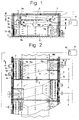
- the drawing shows a preferred embodiment of the heat treatment device according to the invention, namely in the version as a stretching machine for drying and / or fixing a textile web WB.
- the Tensioner contains a largely in the usual way closed device or machine housing 1, in at least one treatment field F is formed; however, as can be seen in FIG. 2, in the direction of web transport (according to arrow 2 in Fig. 2) several immediately successive treatment fields F provided.
- Above and below the - in Fig.1 defined by the web WB itself - Goods web transport level are upper and lower nozzle systems for inflating treatment gas onto the associated arranged upper and lower web pages.
- each Treatment area F the upper nozzle system by a upper nozzle box group 3 and the lower nozzle system formed by a lower nozzle box group 4, wherein this across the treatment range of the stenter reaching nozzle box groups each by a number of individual nozzle boxes in a manner known per se are trained.
- During heat treatment operation can in a conventional manner treatment gas on the Top and bottom sides of the web WB are inflated, as indicated by arrows in Fig.1.
- the Material web is spread out during this heat treatment or wide-spread condition continuously accordingly the arrow 2 in the longitudinal direction through the tensioning machine transported through, for this web transport - as is common in tensioners - endlessly revolving in the area of each length of the web and correspondingly drivable tension chains 6 are provided are.
- two fans 7, 8 provided by which the pressure side 7a of the first fan 7 over a first gas supply channel 9 with the inflow opening 3a the upper nozzle box group 3 and the pressure side 8a of the second fan 8 via a second gas supply channel 10 with the inflow opening 4a of the lower nozzle box group 4 is connected.
- a common treatment gas supply system provided one with the suction sides 7b and 8b of both fans 7, 8 connected Gas intake duct 11, a filter device 12 for Separation of impurities (fibers, lint and the like) from the recirculated air as well as a heating device 13 for heating or reheating the circulating air in front of the fans 7, 8 contains.
- the Gas intake duct 11 approximately across the tensioning machine or transversely to the direction of web transport (arrow 2), where this gas intake duct 11 through a corresponding transition piece 11a to the suction sides 7b, 8b of the two Fans 7, 8 is connected.
- the Bypass valve system for the lower nozzle box group 4 can be relatively simple in terms of equipment or mechanics be trained. It contains a bypass valve 15, which in the present embodiment in which the Pressure side 8a of the second fan 8 with the inflow opening 4a connecting the lower nozzle box group 4 Gas supply channel 9 is arranged.
- This bypass valve 15 can with the help of one indicated in Fig.1 Linkage (adjusting device) 16 between a Open position - as shown in Fig.1 is - in the inflow opening 4a to the lower Nozzle box group 4 is released, and one - in Fig. 1 only indicated by dashed lines - bypass position be adjusted in which the inflow opening 4a is closed, so the flow connection between the second gas supply channel 10 and the lower nozzle box group 4 shut off and thus that of the second fan 8 incoming circulating air directly into a gas recirculation room 19 deflectable within the machine housing 1 is.
- Fig.1 Linkage (adjusting device) 16 between a Open position - as shown in Fig.1 is - in the inflow opening 4a to the lower Nozzle box group 4 is released, and one - in Fig. 1 only indicated by dashed lines - bypass position be adjusted in which the inflow opening 4a is closed, so the flow connection between the second gas supply channel 10 and the lower nozzle box group 4 shut off and thus that of the second
- the drive motor 8c of the second fan 8 of each treatment field F also to provide a frequency converter in such a way that thereby a general quantity regulation of this second fan 8 generated treatment gas flow / circulating air flow can be generated.
- the relatively inexpensive frequency switch these days for the drive motors 7c, 8c of both fans 7, 8 of each treatment field F can thus be energy-saving Way a very precise air volume control made for the upper and lower nozzle box groups 3, 4 be without mechanically complex Throttle valves (with actuators etc.) are provided Need to become.
- a control device 17 is provided in each treatment field F - as indicated by thin lines - on the one hand, at least with the web transport device, thus with the tension chains 6 (or with their drive device) in signal connection and to the other with the frequency switch 14 for the drive motor 7c of the first fan 7 and with a flap actuator 18 is in switching connection, via the linkage 16 is connected to the bypass valve 15.
- This control device 17 is designed such that with a standstill signal from the tension chains 6 via the frequency switch 14, the speed of the first Fan 7 to a minimum value or to zero regulated down or the drive motor 7c of this first Fan 7 can be turned off while at the same time the bypass valve 15 via the valve actuator 18 adjusted in their bypass position mentioned above becomes.
- the control device 17 receives a corresponding signal, so that then via the frequency switch 14 the first fan 7 to its optimal Operating speed regulated and at the same time the bypass flap 15 on the flap 18 in their top explained opening position is reset.
- the control and switching measures described above apply of course equally for all treatment fields F of the tensioner but only one Control device 17 is required.
- the heating device 13 can be used for the circulating air flows generated by both fans 7, 8 common heating device in any suitable Formed in the treatment gas supply system and be arranged.
- the one illustrated in the drawing Embodiment is preferred the heating device by a direct heating, with gas or light fuel-operated burner device 13 form, which is useful on the fans 7, 8th opposite housing longitudinal wall 1b and at least partially arranged within the filter device 12 is and directly via a suction nozzle 11b in the open ends directed towards this longitudinal housing wall 1b of the gas intake duct 11 works.
- the common heating device for both fans 7, 8 of each treatment field F could, if necessary also - in a manner known per se - by one in the area the gas intake duct 11 arranged and from recycled treatment gas flowed through indirect Heat exchanger be formed.
Landscapes
- Engineering & Computer Science (AREA)
- Mechanical Engineering (AREA)
- General Engineering & Computer Science (AREA)
- Life Sciences & Earth Sciences (AREA)
- Chemical & Material Sciences (AREA)
- Combustion & Propulsion (AREA)
- Textile Engineering (AREA)
- Sustainable Development (AREA)
- Treatment Of Fiber Materials (AREA)
- Processing And Handling Of Plastics And Other Materials For Molding In General (AREA)
- Heating, Cooling, Or Curing Plastics Or The Like In General (AREA)
- Drying Of Solid Materials (AREA)
- Tunnel Furnaces (AREA)
- Heat Treatment Of Strip Materials And Filament Materials (AREA)
- Yarns And Mechanical Finishing Of Yarns Or Ropes (AREA)
Abstract
Description
- Fig.1
- eine Querschnittsansicht (etwa entlang der Linie I-I in Fig.2) durch die erfindungsgemäße Wärmebehandlungsvorrichtung;
- Fig.2
- eine teilweise geschnittene Teil-Grundrißansicht (etwa entlang der Linie II-II in Fig.1) der Wärmebehandlungsvorrichtung (bei einer Ausführung mit mehreren unmittelbar aufeinanderfolgenden Behandlungsfeldern).
Claims (7)
- Vorrichtung zur Wärmebehandlung einer im breitgeführten Zustand fortlaufend transportierten Warenbahn (WB), insbesondere zum Trocknen und/oder Fixieren einer textilen Warenbahn, enthaltenda) ein Vorrichtungsgehäuse (1), in dem wenigstens ein Behandlungsfeld (F) ausgebildet ist,b) oberhalb und unterhalb der Warenbahn-Transportebene angeordnete obere und untere Düsensysteme (3, 4) zum Aufblasen von Behandlungsgas auf die entsprechenden Warenbahnseiten,c) zwei im Behandlungsfeld (F) vorgesehene, zur Erzeugung zirkulierender Behandlungsgasströme ausgebildete Ventilatoren (7, 8), von denen die Druckseite (7a) des ersten Ventilators mit der Zuströmöffnung (3a) des oberen Düsensystems (3) und die Druckseite (8a) des zweiten Ventilators (8) mit der Zuströmöffnung (4a) des unteren Düsensystems (4) verbunden ist,d) ein für beide Ventilatoren (7, 8) gemeinsames Behandlungsgas-Zuführsystem, das einen mit den Ansaugseiten (7b, 8b) beider Ventilatoren verbundenen, etwa quer zur Warenbahn-Transportrichtung (2) verlaufenden Gasansaugkanal (11), eine Filtereinrichtung (12) zum Abscheiden von Verunreinigungen aus rückzuführendem Behandlungsgas sowie eine Heizeinrichtung (13) zum Aufheizen des Behandlungsgases vor den Ventilatoren enthält,e) ein Bypass-Klappensystem (15, 16) zum Umlenken von Behandlungsgas um die Warenbahn (WB) bei einem Stillstand des Warenbahn-Transports,
gekennzeichnet durch die Kombination folgender Merkmale:f) das Bypass-Klappensystem (15, 16) ist nur dem einen Düsensystem (4) zugeordnet;g) der das andere Düsensystem (3) mit Behandlungsgas versorgende Ventilator (7) weist einen Antriebsmotor (7c) mit einem zugeordneten Frequenzumschalter (14) auf, durch den dieser Ventilator bei einem Stillstand des WarenbahnTransports auf Minimaldrehzahl herunterregelbar oder abschaltbar ist. - Vorrichtung nach Anspruch 1, dadurch gekennzeichnet, daß das Bypass-Klappensystem (15, 16) dem unteren Düsensystem (4) und der durch den Frequenzumschalter (14) regelbare erste Ventilator (7) dem oberen Düsensystem (3) zugeordnet ist.
- Vorrichtung nach Anspruch 2, dadurch gekennzeichnet, daß das Bypass-Klappensystem eine Bypassklappe (15) enthält, die in einem die Druckseite (8a) des zweiten Ventilators (8) mit der Zuströmöffnung (4a) des unteren Düsensystems (4) verbindenden Gaszuführkanal (9) angeordnet und die zwischen einer Öffnungsstellung, in der die Zuströmöffnung (4a) zum unteren Düsensystem (4) freigegeben ist, und einer Bypassstellung verstellbar ist, in der die Strömungsverbindung zum unteren Düsensystem (4) abgesperrt und das vom zweiten Ventilator (8) zuströmende Behandlungsgas direkt in einen Gasrückführraum (19) innerhalb des Vorrichtungsgehäuses (1) umlenkbar ist.
- Vorrichtung nach Anspruch 3, dadurch gekennzeichnet, daß eine Steuereinrichtung (17) vorgesehen ist, die zum einen zumindest mit einer Warenbahn-Transporteinrichtung (6) in Signalverbindung und zum andern mit dem Frequenzumformer (14) des Antriebsmotors (7c) für den ersten Ventilator (7) sowie mit einem Klappensteller (18) in Schaltverbindung steht, der über eine Stelleinrichtung (16) mit der Bypassklappe (15) verbunden ist, wobei diese Steuereinrichtung (17) derart ausgeführt ist, daß bei einem Stillstandssignal von der Warenbahn-Transporteinrichtung (6) über den Frequenzumschalter die Drehzahl des ersten Ventilators (7) auf einen Minimalwert oder auf Null herunterregelbar und gleichzeitig die Bypassklappe (15) über den Klappensteller (18) in ihre Bypassstellung verstellbar ist.
- Vorrichtung nach Anspruch 1, dadurch gekennzeichnet, daß dem Antriebsmotor (8c) des anderen Ventilators (8) des (jedes) Behandlungsfeldes (F) ein Frequenzumschalter zur allgemeinen Mengenregelung des von diesem Ventilator erzeugten Behandlungsgasstromes zugeordnet ist.
- Vorrichtung nach wenigstens einen der Ansprüche 1 bis 5, gekennzeichnet durch ihre Ausführung als Spannmaschine zum Trocknen und/oder Fixieren einer textilen Warenbahn (WB), wobei im Vorrichtungsgehäuse (1) in Warenbahn-Transportrichtung (2) mehrere unmittelbar aufeinanderfolgende Behandlungsfelder (F) vorgesehen sind, in denen die zirkulierenden Behandlungsgasströme durch Umluftströme gebildet sind, wobei in jedem Behandlungsfeld (F) ein gesondertes Umluftsystem mit zwei Ventilatoren (5), einer oberen und einer unteren Düsenkastengruppe (3, 4) als Düsensysteme sowie mit einem gemeinsamen Behandlungsgas-Zuführsystem angeordnet ist, wobei ferner alle Behandlungsfelder (F) im wesentlichen in gleicher Weise baukastenartig aufgebaut und in Warenbahn-Transportrichtung (2) aufeinanderfolgende Behandlungsfelder (F) - im Grundriß der Vorrichtung betrachtet - in bezug auf ihre Umluftsysteme jeweils spiegelbildlich zueinander angeordnet sind.
- Vorrichtung nach Anspruch 1 und/oder 6, dadurch gekennzeichnet, daß die Heizeinrichtung des Behandlungsgas-Zuführsystems durch eine direkt heizende, mit Gas oder leichtem Heizöl betriebene Brennereinrichtung (13) oder durch einen im Bereich des Gasansaugkanales (11) angeordneten, von Behandlungsgas durchströmten indirekten Wärmetauscher gebildet ist.
Applications Claiming Priority (2)
| Application Number | Priority Date | Filing Date | Title |
|---|---|---|---|
| DE19844692 | 1998-09-29 | ||
| DE19844692A DE19844692A1 (de) | 1998-09-29 | 1998-09-29 | Vorrichtung zur Wärmebehandlung einer Warenbahn |
Publications (3)
| Publication Number | Publication Date |
|---|---|
| EP0990867A2 true EP0990867A2 (de) | 2000-04-05 |
| EP0990867A3 EP0990867A3 (de) | 2001-09-12 |
| EP0990867B1 EP0990867B1 (de) | 2004-02-11 |
Family
ID=7882684
Family Applications (1)
| Application Number | Title | Priority Date | Filing Date |
|---|---|---|---|
| EP99116983A Expired - Lifetime EP0990867B1 (de) | 1998-09-29 | 1999-08-27 | Vorrichtung zur Wärmebehandlung einer Warenbahn |
Country Status (5)
| Country | Link |
|---|---|
| EP (1) | EP0990867B1 (de) |
| AT (1) | ATE259495T1 (de) |
| DE (2) | DE19844692A1 (de) |
| ES (1) | ES2216394T3 (de) |
| PT (1) | PT990867E (de) |
Cited By (2)
| Publication number | Priority date | Publication date | Assignee | Title |
|---|---|---|---|---|
| US8046934B2 (en) * | 2006-01-25 | 2011-11-01 | Nv Bekaert Sa | Convective system for a dryer installation |
| CN119642541A (zh) * | 2024-12-13 | 2025-03-18 | 江西昌硕户外休闲用品有限公司 | 一种用于复合型纺织面料生产的烘干装置 |
Citations (2)
| Publication number | Priority date | Publication date | Assignee | Title |
|---|---|---|---|---|
| DE303887C (de) | ||||
| DE29801875U1 (de) | 1998-02-04 | 1998-03-26 | Brückner Apparatebau GmbH, 64711 Erbach | Vorrichtung zur Wärmebehandlung einer Warenbahn |
Family Cites Families (8)
| Publication number | Priority date | Publication date | Assignee | Title |
|---|---|---|---|---|
| DE2201731A1 (de) * | 1972-01-14 | 1973-07-19 | Brueckner Trockentechnik Kg | Vorrichtung zur waermebehandlung einer flaechenhaften warenbahn |
| US4200994A (en) * | 1977-08-05 | 1980-05-06 | Edgar Pickering (Blackburn) Ltd. | Drying apparatus |
| DE3239250A1 (de) * | 1982-10-23 | 1984-04-26 | Dirk Dipl.-Ing. 2000 Hamburg Bohm | Anordnung zur einstellung der abluftmenge insbes. bei trocknern |
| DE3627904A1 (de) * | 1986-08-16 | 1988-02-18 | Monforts Gmbh & Co A | Konvektionstrocken- und/oder -fixiermaschine |
| DD255201B5 (de) * | 1986-12-19 | 1994-03-10 | Textilmaschinenbau Gera Gmbh | Vorrichtung zur waermebehandlung von warenbahnen, insbesondere textilbahnen |
| DE3727280A1 (de) * | 1987-08-16 | 1989-03-02 | Brueckner Trockentechnik Gmbh | Vorrichtung zur waermebehandlung einer warenbahn |
| DE4026107A1 (de) * | 1990-08-17 | 1992-02-20 | Monforts Gmbh & Co A | Konvektions-trocken und/oder -fixiermaschine |
| DE4033637A1 (de) * | 1990-10-23 | 1992-04-30 | Babcock Textilmasch | Vorrichtung zur umluftmengenregelung bei waermebehandlungsvorrichtungen, wie trocknern und dgl. |
-
1998
- 1998-09-29 DE DE19844692A patent/DE19844692A1/de not_active Ceased
-
1999
- 1999-08-27 AT AT99116983T patent/ATE259495T1/de active
- 1999-08-27 DE DE59908500T patent/DE59908500D1/de not_active Expired - Lifetime
- 1999-08-27 ES ES99116983T patent/ES2216394T3/es not_active Expired - Lifetime
- 1999-08-27 PT PT99116983T patent/PT990867E/pt unknown
- 1999-08-27 EP EP99116983A patent/EP0990867B1/de not_active Expired - Lifetime
Patent Citations (2)
| Publication number | Priority date | Publication date | Assignee | Title |
|---|---|---|---|---|
| DE303887C (de) | ||||
| DE29801875U1 (de) | 1998-02-04 | 1998-03-26 | Brückner Apparatebau GmbH, 64711 Erbach | Vorrichtung zur Wärmebehandlung einer Warenbahn |
Cited By (2)
| Publication number | Priority date | Publication date | Assignee | Title |
|---|---|---|---|---|
| US8046934B2 (en) * | 2006-01-25 | 2011-11-01 | Nv Bekaert Sa | Convective system for a dryer installation |
| CN119642541A (zh) * | 2024-12-13 | 2025-03-18 | 江西昌硕户外休闲用品有限公司 | 一种用于复合型纺织面料生产的烘干装置 |
Also Published As
| Publication number | Publication date |
|---|---|
| DE19844692A1 (de) | 2000-03-30 |
| EP0990867A3 (de) | 2001-09-12 |
| ES2216394T3 (es) | 2004-10-16 |
| EP0990867B1 (de) | 2004-02-11 |
| DE59908500D1 (de) | 2004-03-18 |
| PT990867E (pt) | 2004-06-30 |
| ATE259495T1 (de) | 2004-02-15 |
Similar Documents
| Publication | Publication Date | Title |
|---|---|---|
| DE3910898B4 (de) | Verfahren zum Trocknen einer sich bewegenden Bahn und Kombinationstrockner | |
| DE3890457C2 (de) | Verfahren zum berührungsfreien Trocknen einer Papier- oder Kartonbahn | |
| WO1987006284A1 (fr) | Systeme pour la recuperation de la chaleur perdue contenue dans l'air d'evacuation provenant des sechoirs pour machines a papier | |
| EP0264637B1 (de) | Durchlauftrockner für Materialbahnen, insbesondere Offset-Trockner | |
| EP0778131B1 (de) | Bogenführsystem für eine Druckmaschine | |
| DE2534479C2 (de) | Temperatursteuereinrichtung bei einer Trockenmaschine für laufende Garnbahnen | |
| EP1101074A1 (de) | Trockner und verfahren zum trocknen von kontinuierlich geförderter ware | |
| EP0319681B1 (de) | Vorrichtung zur Wärmebehandlung einer breitgeführten textilen Warenbahn | |
| EP0266684A2 (de) | Verfahren zum Regenerieren einer mit Feuchtigkeit beladenen Trocknungspatrone sowie Trockner mit einer Regeneriervorrichtung zur Durchführung eines solchen Verfahrens | |
| DE2908348A1 (de) | Schwebetrockner | |
| DE2616347C3 (de) | Durchlauftrockner für Warenbahnen | |
| DE69715963T2 (de) | Vorrichtung und Verfahren zum Trocknen einer feuchten Bahn und zum Modifizieren seines Feuchtigkeitsprofils | |
| DE19525545C1 (de) | Trockner für durchlaufende Textilbahnen | |
| DE3336331C2 (de) | Konvektionstrocken- und/oder -fixiermaschine | |
| EP0990867B1 (de) | Vorrichtung zur Wärmebehandlung einer Warenbahn | |
| DE102007051962A1 (de) | Materialbahntrockneranordnung | |
| EP1262726A1 (de) | Vorrichtung zur Behandlung von textilen Warenbahnen | |
| EP0935112B1 (de) | Vorrichtung zur Wärmebehandlung einer Warenbahn | |
| EP0303887B1 (de) | Vorrichtung zur Wärmebehandlung einer Warenbahn | |
| DE102024106682B4 (de) | Vorrichtung zur Wärmebehandlung einer Warenbahn | |
| EP0810413A1 (de) | Trocken-und/oder Fixiervorrichtung | |
| EP0294729B1 (de) | Raumlufttechnisches Gerät | |
| AT401104B (de) | Wärmebehandlungsmaschine mit förderung des behandelten gutes und verfahren zum betrieb dieser wärmebehandlungsmaschine | |
| EP0470418B1 (de) | Trockner für Filmentwicklungsgeräte | |
| EP1024336B1 (de) | Trocknungsanlage |
Legal Events
| Date | Code | Title | Description |
|---|---|---|---|
| PUAI | Public reference made under article 153(3) epc to a published international application that has entered the european phase |
Free format text: ORIGINAL CODE: 0009012 |
|
| AK | Designated contracting states |
Kind code of ref document: A2 Designated state(s): AT BE CH CY DE DK ES FI FR GB GR IE IT LI LU MC NL PT SE |
|
| AX | Request for extension of the european patent |
Free format text: AL;LT;LV;MK;RO;SI |
|
| PUAL | Search report despatched |
Free format text: ORIGINAL CODE: 0009013 |
|
| AK | Designated contracting states |
Kind code of ref document: A3 Designated state(s): AT BE CH CY DE DK ES FI FR GB GR IE IT LI LU MC NL PT SE |
|
| AX | Request for extension of the european patent |
Free format text: AL;LT;LV;MK;RO;SI |
|
| 17P | Request for examination filed |
Effective date: 20010913 |
|
| AKX | Designation fees paid |
Free format text: AT BE CH CY DE DK ES FI FR GB GR IE IT LI LU MC NL PT SE |
|
| RAP1 | Party data changed (applicant data changed or rights of an application transferred) |
Owner name: BRUECKNER TROCKENTECHNIK GMBH & CO. KG |
|
| GRAP | Despatch of communication of intention to grant a patent |
Free format text: ORIGINAL CODE: EPIDOSNIGR1 |
|
| GRAS | Grant fee paid |
Free format text: ORIGINAL CODE: EPIDOSNIGR3 |
|
| GRAA | (expected) grant |
Free format text: ORIGINAL CODE: 0009210 |
|
| AK | Designated contracting states |
Kind code of ref document: B1 Designated state(s): AT BE CH CY DE DK ES FI FR GB GR IE IT LI LU MC NL PT SE |
|
| PG25 | Lapsed in a contracting state [announced via postgrant information from national office to epo] |
Ref country code: NL Free format text: LAPSE BECAUSE OF FAILURE TO SUBMIT A TRANSLATION OF THE DESCRIPTION OR TO PAY THE FEE WITHIN THE PRESCRIBED TIME-LIMIT Effective date: 20040211 Ref country code: IE Free format text: LAPSE BECAUSE OF FAILURE TO SUBMIT A TRANSLATION OF THE DESCRIPTION OR TO PAY THE FEE WITHIN THE PRESCRIBED TIME-LIMIT Effective date: 20040211 Ref country code: GB Free format text: LAPSE BECAUSE OF FAILURE TO SUBMIT A TRANSLATION OF THE DESCRIPTION OR TO PAY THE FEE WITHIN THE PRESCRIBED TIME-LIMIT Effective date: 20040211 Ref country code: FR Free format text: LAPSE BECAUSE OF FAILURE TO SUBMIT A TRANSLATION OF THE DESCRIPTION OR TO PAY THE FEE WITHIN THE PRESCRIBED TIME-LIMIT Effective date: 20040211 Ref country code: FI Free format text: LAPSE BECAUSE OF FAILURE TO SUBMIT A TRANSLATION OF THE DESCRIPTION OR TO PAY THE FEE WITHIN THE PRESCRIBED TIME-LIMIT Effective date: 20040211 Ref country code: CY Free format text: LAPSE BECAUSE OF FAILURE TO SUBMIT A TRANSLATION OF THE DESCRIPTION OR TO PAY THE FEE WITHIN THE PRESCRIBED TIME-LIMIT Effective date: 20040211 |
|
| REG | Reference to a national code |
Ref country code: GB Ref legal event code: FG4D Free format text: NOT ENGLISH |
|
| REG | Reference to a national code |
Ref country code: CH Ref legal event code: EP |
|
| REG | Reference to a national code |
Ref country code: IE Ref legal event code: FG4D Free format text: GERMAN |
|
| REG | Reference to a national code |
Ref country code: CH Ref legal event code: NV Representative=s name: RIEDERER HASLER & PARTNER PATENTANWAELTE AG |
|
| REF | Corresponds to: |
Ref document number: 59908500 Country of ref document: DE Date of ref document: 20040318 Kind code of ref document: P |
|
| PG25 | Lapsed in a contracting state [announced via postgrant information from national office to epo] |
Ref country code: SE Free format text: LAPSE BECAUSE OF FAILURE TO SUBMIT A TRANSLATION OF THE DESCRIPTION OR TO PAY THE FEE WITHIN THE PRESCRIBED TIME-LIMIT Effective date: 20040511 Ref country code: GR Free format text: LAPSE BECAUSE OF FAILURE TO SUBMIT A TRANSLATION OF THE DESCRIPTION OR TO PAY THE FEE WITHIN THE PRESCRIBED TIME-LIMIT Effective date: 20040511 Ref country code: DK Free format text: LAPSE BECAUSE OF FAILURE TO SUBMIT A TRANSLATION OF THE DESCRIPTION OR TO PAY THE FEE WITHIN THE PRESCRIBED TIME-LIMIT Effective date: 20040511 |
|
| REG | Reference to a national code |
Ref country code: PT Ref legal event code: SC4A Free format text: AVAILABILITY OF NATIONAL TRANSLATION Effective date: 20040510 |
|
| NLV1 | Nl: lapsed or annulled due to failure to fulfill the requirements of art. 29p and 29m of the patents act | ||
| GBV | Gb: ep patent (uk) treated as always having been void in accordance with gb section 77(7)/1977 [no translation filed] |
Effective date: 20040211 |
|
| PG25 | Lapsed in a contracting state [announced via postgrant information from national office to epo] |
Ref country code: LU Free format text: LAPSE BECAUSE OF NON-PAYMENT OF DUE FEES Effective date: 20040827 |
|
| PG25 | Lapsed in a contracting state [announced via postgrant information from national office to epo] |
Ref country code: MC Free format text: LAPSE BECAUSE OF NON-PAYMENT OF DUE FEES Effective date: 20040831 Ref country code: BE Free format text: LAPSE BECAUSE OF NON-PAYMENT OF DUE FEES Effective date: 20040831 |
|
| REG | Reference to a national code |
Ref country code: IE Ref legal event code: FD4D |
|
| REG | Reference to a national code |
Ref country code: ES Ref legal event code: FG2A Ref document number: 2216394 Country of ref document: ES Kind code of ref document: T3 |
|
| PLBQ | Unpublished change to opponent data |
Free format text: ORIGINAL CODE: EPIDOS OPPO |
|
| PLBI | Opposition filed |
Free format text: ORIGINAL CODE: 0009260 |
|
| PLAX | Notice of opposition and request to file observation + time limit sent |
Free format text: ORIGINAL CODE: EPIDOSNOBS2 |
|
| 26 | Opposition filed |
Opponent name: MOENUS TEXTILMASCHINEN GMBH Effective date: 20041111 |
|
| EN | Fr: translation not filed | ||
| BERE | Be: lapsed |
Owner name: *BRUCKNER TROCKENTECHNIK G.M.B.H. & CO. K.G. Effective date: 20040831 |
|
| PLBB | Reply of patent proprietor to notice(s) of opposition received |
Free format text: ORIGINAL CODE: EPIDOSNOBS3 |
|
| PLBB | Reply of patent proprietor to notice(s) of opposition received |
Free format text: ORIGINAL CODE: EPIDOSNOBS3 |
|
| PLCK | Communication despatched that opposition was rejected |
Free format text: ORIGINAL CODE: EPIDOSNREJ1 |
|
| APBP | Date of receipt of notice of appeal recorded |
Free format text: ORIGINAL CODE: EPIDOSNNOA2O |
|
| APAH | Appeal reference modified |
Free format text: ORIGINAL CODE: EPIDOSCREFNO |
|
| APBQ | Date of receipt of statement of grounds of appeal recorded |
Free format text: ORIGINAL CODE: EPIDOSNNOA3O |
|
| BERE | Be: lapsed |
Owner name: *BRUCKNER TROCKENTECHNIK G.M.B.H. & CO. K.G. Effective date: 20040831 |
|
| APBU | Appeal procedure closed |
Free format text: ORIGINAL CODE: EPIDOSNNOA9O |
|
| PLBN | Opposition rejected |
Free format text: ORIGINAL CODE: 0009273 |
|
| STAA | Information on the status of an ep patent application or granted ep patent |
Free format text: STATUS: OPPOSITION REJECTED |
|
| 27O | Opposition rejected |
Effective date: 20090526 |
|
| PGFP | Annual fee paid to national office [announced via postgrant information from national office to epo] |
Ref country code: ES Payment date: 20110812 Year of fee payment: 13 Ref country code: PT Payment date: 20110823 Year of fee payment: 13 Ref country code: AT Payment date: 20110812 Year of fee payment: 13 |
|
| REG | Reference to a national code |
Ref country code: PT Ref legal event code: MM4A Free format text: LAPSE DUE TO NON-PAYMENT OF FEES Effective date: 20130227 |
|
| REG | Reference to a national code |
Ref country code: AT Ref legal event code: MM01 Ref document number: 259495 Country of ref document: AT Kind code of ref document: T Effective date: 20120827 |
|
| PG25 | Lapsed in a contracting state [announced via postgrant information from national office to epo] |
Ref country code: PT Free format text: LAPSE BECAUSE OF NON-PAYMENT OF DUE FEES Effective date: 20130227 |
|
| PG25 | Lapsed in a contracting state [announced via postgrant information from national office to epo] |
Ref country code: AT Free format text: LAPSE BECAUSE OF NON-PAYMENT OF DUE FEES Effective date: 20120827 |
|
| REG | Reference to a national code |
Ref country code: ES Ref legal event code: FD2A Effective date: 20131018 |
|
| PG25 | Lapsed in a contracting state [announced via postgrant information from national office to epo] |
Ref country code: ES Free format text: LAPSE BECAUSE OF NON-PAYMENT OF DUE FEES Effective date: 20120828 |
|
| PGFP | Annual fee paid to national office [announced via postgrant information from national office to epo] |
Ref country code: CH Payment date: 20170821 Year of fee payment: 19 Ref country code: IT Payment date: 20170823 Year of fee payment: 19 |
|
| PGFP | Annual fee paid to national office [announced via postgrant information from national office to epo] |
Ref country code: DE Payment date: 20171024 Year of fee payment: 19 |
|
| REG | Reference to a national code |
Ref country code: DE Ref legal event code: R119 Ref document number: 59908500 Country of ref document: DE |
|
| REG | Reference to a national code |
Ref country code: CH Ref legal event code: PL |
|
| PG25 | Lapsed in a contracting state [announced via postgrant information from national office to epo] |
Ref country code: CH Free format text: LAPSE BECAUSE OF NON-PAYMENT OF DUE FEES Effective date: 20180831 Ref country code: LI Free format text: LAPSE BECAUSE OF NON-PAYMENT OF DUE FEES Effective date: 20180831 |
|
| PG25 | Lapsed in a contracting state [announced via postgrant information from national office to epo] |
Ref country code: IT Free format text: LAPSE BECAUSE OF NON-PAYMENT OF DUE FEES Effective date: 20180827 Ref country code: DE Free format text: LAPSE BECAUSE OF NON-PAYMENT OF DUE FEES Effective date: 20190301 |