EP0991141A2 - Connecteur de montage en surface - Google Patents
Connecteur de montage en surface Download PDFInfo
- Publication number
- EP0991141A2 EP0991141A2 EP99650051A EP99650051A EP0991141A2 EP 0991141 A2 EP0991141 A2 EP 0991141A2 EP 99650051 A EP99650051 A EP 99650051A EP 99650051 A EP99650051 A EP 99650051A EP 0991141 A2 EP0991141 A2 EP 0991141A2
- Authority
- EP
- European Patent Office
- Prior art keywords
- metal member
- board
- housing
- reinforcing metal
- mount connector
- Prior art date
- Legal status (The legal status is an assumption and is not a legal conclusion. Google has not performed a legal analysis and makes no representation as to the accuracy of the status listed.)
- Withdrawn
Links
Images


Classifications
-
- H—ELECTRICITY
- H05—ELECTRIC TECHNIQUES NOT OTHERWISE PROVIDED FOR
- H05K—PRINTED CIRCUITS; CASINGS OR CONSTRUCTIONAL DETAILS OF ELECTRIC APPARATUS; MANUFACTURE OF ASSEMBLAGES OF ELECTRICAL COMPONENTS
- H05K3/00—Apparatus or processes for manufacturing printed circuits
- H05K3/30—Assembling printed circuits with electric components, e.g. with resistors
- H05K3/32—Assembling printed circuits with electric components, e.g. with resistors electrically connecting electric components or wires to printed circuits
- H05K3/34—Assembling printed circuits with electric components, e.g. with resistors electrically connecting electric components or wires to printed circuits by soldering
- H05K3/341—Surface mounted components
-
- H—ELECTRICITY
- H01—ELECTRIC ELEMENTS
- H01R—ELECTRICALLY-CONDUCTIVE CONNECTIONS; STRUCTURAL ASSOCIATIONS OF A PLURALITY OF MUTUALLY-INSULATED ELECTRICAL CONNECTING ELEMENTS; COUPLING DEVICES; CURRENT COLLECTORS
- H01R12/00—Structural associations of a plurality of mutually-insulated electrical connecting elements, specially adapted for printed circuits, e.g. printed circuit boards [PCB], flat or ribbon cables, or like generally planar structures, e.g. terminal strips, terminal blocks; Coupling devices specially adapted for printed circuits, flat or ribbon cables, or like generally planar structures; Terminals specially adapted for contact with, or insertion into, printed circuits, flat or ribbon cables, or like generally planar structures
- H01R12/70—Coupling devices
- H01R12/71—Coupling devices for rigid printing circuits or like structures
- H01R12/712—Coupling devices for rigid printing circuits or like structures co-operating with the surface of the printed circuit or with a coupling device exclusively provided on the surface of the printed circuit
- H01R12/716—Coupling device provided on the PCB
-
- H—ELECTRICITY
- H05—ELECTRIC TECHNIQUES NOT OTHERWISE PROVIDED FOR
- H05K—PRINTED CIRCUITS; CASINGS OR CONSTRUCTIONAL DETAILS OF ELECTRIC APPARATUS; MANUFACTURE OF ASSEMBLAGES OF ELECTRICAL COMPONENTS
- H05K2201/00—Indexing scheme relating to printed circuits covered by H05K1/00
- H05K2201/09—Shape and layout
- H05K2201/09209—Shape and layout details of conductors
- H05K2201/09654—Shape and layout details of conductors covering at least two types of conductors provided for in H05K2201/09218 - H05K2201/095
- H05K2201/09781—Dummy conductors, i.e. not used for normal transport of current; Dummy electrodes of components
-
- H—ELECTRICITY
- H05—ELECTRIC TECHNIQUES NOT OTHERWISE PROVIDED FOR
- H05K—PRINTED CIRCUITS; CASINGS OR CONSTRUCTIONAL DETAILS OF ELECTRIC APPARATUS; MANUFACTURE OF ASSEMBLAGES OF ELECTRICAL COMPONENTS
- H05K2201/00—Indexing scheme relating to printed circuits covered by H05K1/00
- H05K2201/10—Details of components or other objects attached to or integrated in a printed circuit board
- H05K2201/10007—Types of components
- H05K2201/10189—Non-printed connector
-
- H—ELECTRICITY
- H05—ELECTRIC TECHNIQUES NOT OTHERWISE PROVIDED FOR
- H05K—PRINTED CIRCUITS; CASINGS OR CONSTRUCTIONAL DETAILS OF ELECTRIC APPARATUS; MANUFACTURE OF ASSEMBLAGES OF ELECTRICAL COMPONENTS
- H05K2201/00—Indexing scheme relating to printed circuits covered by H05K1/00
- H05K2201/10—Details of components or other objects attached to or integrated in a printed circuit board
- H05K2201/10613—Details of electrical connections of non-printed components, e.g. special leads
- H05K2201/10621—Components characterised by their electrical contacts
- H05K2201/10659—Different types of terminals for the same component, e.g. solder balls combined with leads
-
- H—ELECTRICITY
- H05—ELECTRIC TECHNIQUES NOT OTHERWISE PROVIDED FOR
- H05K—PRINTED CIRCUITS; CASINGS OR CONSTRUCTIONAL DETAILS OF ELECTRIC APPARATUS; MANUFACTURE OF ASSEMBLAGES OF ELECTRICAL COMPONENTS
- H05K2203/00—Indexing scheme relating to apparatus or processes for manufacturing printed circuits covered by H05K3/00
- H05K2203/30—Details of processes not otherwise provided for in H05K2203/01 - H05K2203/17
- H05K2203/306—Lifting the component during or after mounting; Increasing the gap between component and PCB
-
- H—ELECTRICITY
- H05—ELECTRIC TECHNIQUES NOT OTHERWISE PROVIDED FOR
- H05K—PRINTED CIRCUITS; CASINGS OR CONSTRUCTIONAL DETAILS OF ELECTRIC APPARATUS; MANUFACTURE OF ASSEMBLAGES OF ELECTRICAL COMPONENTS
- H05K3/00—Apparatus or processes for manufacturing printed circuits
- H05K3/30—Assembling printed circuits with electric components, e.g. with resistors
- H05K3/32—Assembling printed circuits with electric components, e.g. with resistors electrically connecting electric components or wires to printed circuits
- H05K3/34—Assembling printed circuits with electric components, e.g. with resistors electrically connecting electric components or wires to printed circuits by soldering
- H05K3/341—Surface mounted components
- H05K3/3421—Leaded components
- H05K3/3426—Leaded components characterised by the leads
-
- Y—GENERAL TAGGING OF NEW TECHNOLOGICAL DEVELOPMENTS; GENERAL TAGGING OF CROSS-SECTIONAL TECHNOLOGIES SPANNING OVER SEVERAL SECTIONS OF THE IPC; TECHNICAL SUBJECTS COVERED BY FORMER USPC CROSS-REFERENCE ART COLLECTIONS [XRACs] AND DIGESTS
- Y02—TECHNOLOGIES OR APPLICATIONS FOR MITIGATION OR ADAPTATION AGAINST CLIMATE CHANGE
- Y02P—CLIMATE CHANGE MITIGATION TECHNOLOGIES IN THE PRODUCTION OR PROCESSING OF GOODS
- Y02P70/00—Climate change mitigation technologies in the production process for final industrial or consumer products
- Y02P70/50—Manufacturing or production processes characterised by the final manufactured product
Definitions
- the present invention relates to surface-mount connector with a reinforcing metal member and, particularly, to a surface-mount connector with a movably attached reinforcing metal member (and lead terminals).
- Fig. 6 shows a conventional surface-mount connector with a reinforcing metal member.
- This connector is of the "header” type and is used together with a receptacle type connector.
- the present invention is applicable to a variety of connector types in addition to both the above types.
- the surface-mount connector is fixed to a board by soldering a plurality of lead terminals 1 which are press fixed to the connector.
- a pair of reinforcing metal members 2 are provided to fix the connector to the board more securely. They are fixed to the housing 3 and then soldered to the board. It is also difficult to have the reinforcing metal members 2 flush with the lead terminals 1. Consequently, it is difficult to fix the connector to the board at a predetermined height. Accordingly, there is a demand for a connector having a high degree of flatness of surface mount.
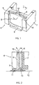
- FIG. 1 shows an end of a surface-mount connector according to an embodiment of the invention, with the other end having the same structure.
- a connector 4 comprises a plurality of lead terminals, a pair of reinforcing metal members 5, a pair of fixing metal members 6, and a housing 7.
- the lead terminals are not shown for simplification but, as shown in Fig. 6, are provided along the length of the housing 7 such that the end portions project outwardly from the bottom of the housing 7.
- the lead terminals are fixed to the housing (or, hereinafter described, are movable with respect to the housing).
- the end portions are soldered to traces of a board by the reflow process.
- the reinforcing metal members 5 are used to firmly secure the connector to the board. They have an L-shaped section.
- the vertical section 8 is not only supported by the housing 7 but also fixed to the fixing metal member 6 while the horizontal section 9 is fixed to the board.
- the reinforcing metal members 5 are not always fixed to the housing but movable with respect to the housing when they are soldered to the board and then fixed to the housing after the soldering.
- the fixing metal member 6 is used to fix the reinforcing metal member 5 to the housing 7. Its shape and size are substantially the same as the vertical sections of the reinforcing metal member 5. It is not necessary when the housing is made from a metal or a material which can be soldered, but it is necessary when the housing is made from a resin or a material which cannot be soldered. When the housing is made from a material which cannot be soldered, the fixing metal member is provided near the reinforcing metal member to fix the reinforcing metal member to the housing indirectly.
- the reinforcing and fixing metal members 5 and 6 are held in the accommodation section 10 at an end of the housing 7.
- the accommodation section 10 extends vertically from the bottom of the housing so that the fixing metal member 6 does not fall from the accommodation section.
- the width of the vertical support section 8 of the reinforcing metal member 5 is slightly smaller than that of the accommodation section 10 while the width of the fixing metal member 6 is slightly larger than that of the accommodation section 10.
- the thickness of the reinforcing and fixing metal members 5 and 6 are substantially equal, with the total thickness of these is slightly smaller than that of the accommodation section 10. Consequently, the fixing metal member 6 is press fixed to the accommodation section 10 so that it is fixed to the housing 7 while the reinforcing metal member 5 is not fixed to the housing 7 when the housing is soldered to the board.
- the reinforcing metal member 5 is vertically movable with respect to the housing.
- the connector When the connector is fixed to the board, it is possible to adjust the height of the reinforcing metal member 5 to thereby maximize the degree of flatness of the connector with respect to the board. That is, it is possible to fix the connector in parallel to the board by automatic adjustment in accordance with the varying distances between the housing and the board due to different materials of the lead terminals and the reinforcing metal members.
- the height adjustment is made automatically by free fall of the reinforcing metal member or pushing-up of the reinforcing metal member by the board, and no manual or mechanical operation is necessary.
- a pair of semi-circular grooves 14 extend vertically in the center of the reinforcing metal member 5 to form small gaps between the grooves 14 and the fixing metal member 6. These gaps enable to solder the reinforcing and fixing metal members 5 and 6 as described below.
- Fig. 2 is a section taken along line 2-2 of Fig. 1 and shows the gap between the groove of the reinforcing metal member 5 and the fixing metal member 6.
- a solder cream 11 is provided at a predetermined portion of a pad 13 on a board 12 to fix the reinforcing metal member 5 to both the board 12 and the fixing metal member 6.
- the solder cream 11 is melted in the reflow process for the lead terminals to fill a gap between the reinforcing metal member 5 and the pad 13. At the same time, it fills the gap between the groove 14 of the reinforcing metal member and the fixing metal member 6 by the capillary effects.
- the solder cream then is let to become cool and solid to thereby secure the reinforcing metal member 5 to the board 12 and the fixing metal member 6.
- the solder cream is suitable for soldering by the capillary effects but other solder may be used.
- the groove 14 may be replaced any gap between the reinforcing and fixing metal members which is able to achieve soldering by the capillary effects.
- the invention it is possible to maintain the adjusted height of the reinforcing metal member throughout a series of operations by providing the reinforcing metal member in movable relation to the fixing metal member and soldering the reinforcing metal member to both the connector and the board by the reflow process for soldering lead terminals to the board.
- a pair of metal sheets or shield plates 15A or 15B are used to form a housing 7 to eliminate the fixing metal members 6 so that a reinforcing metal member 5A or 5B can be soldered directly to the shield plates 15A or 15B.
- the flat shield plates 15A are attached to the inside walls of the C-shaped reinforcing metal member 5A while, in Fig. 4, the L-shaped shield plates 15B have bends 16B which are attached to the reinforcing metal member 5B.
- An opening 16 (Fig. 5) is provided in each of the shield plates 15A and 15B while a pair of protruded portions 7 are provided in the vertical section of the reinforcing metal member 5A or 5B. Consequently, the reinforcing metal members 5A and 5B are attached to the shield plates such that they are vertically movable with respect to the board, permitting automatic adjustment in height of the reinforcing metal members.
- Fig. 5 is a sectional view taken along line 5-5 of Fig. 3 or 4.
- the reinforcing metal members are movably attached to the housing, it is possible to movably attach lead terminals to the housing.
- the connector is conceivable to extend laterally.
- the reflow process by heat described above may be replaced by a reflow process by ultrasonic or laser.
- the shield plate is provided in the middle of a connector, the reinforcing metal member may be movably attached to the central shield plate in the same manner as described above.
- the invention is applicable to other surface-mount connectors than that of Fig. 6.
- the groove to form a gap may be provided in the fixing metal member or shield plate, or a combination of the reinforcing metal member or lead terminal and the fixing metal member or shield plate.
- the height of the reinforcing metal members are automatically adjusted so that the degree of flatness of the connector with respect to the board is increased.
Landscapes
- Engineering & Computer Science (AREA)
- Manufacturing & Machinery (AREA)
- Microelectronics & Electronic Packaging (AREA)
- Coupling Device And Connection With Printed Circuit (AREA)
- Multi-Conductor Connections (AREA)
Applications Claiming Priority (2)
| Application Number | Priority Date | Filing Date | Title |
|---|---|---|---|
| JP27992598 | 1998-10-01 | ||
| JP10279925A JP2000113926A (ja) | 1998-10-01 | 1998-10-01 | 表面実装型コネクタ |
Publications (2)
| Publication Number | Publication Date |
|---|---|
| EP0991141A2 true EP0991141A2 (fr) | 2000-04-05 |
| EP0991141A3 EP0991141A3 (fr) | 2002-02-13 |
Family
ID=17617830
Family Applications (1)
| Application Number | Title | Priority Date | Filing Date |
|---|---|---|---|
| EP99650051A Withdrawn EP0991141A3 (fr) | 1998-10-01 | 1999-06-21 | Connecteur de montage en surface |
Country Status (4)
| Country | Link |
|---|---|
| US (1) | US6254429B1 (fr) |
| EP (1) | EP0991141A3 (fr) |
| JP (1) | JP2000113926A (fr) |
| TW (1) | TW421982B (fr) |
Cited By (3)
| Publication number | Priority date | Publication date | Assignee | Title |
|---|---|---|---|---|
| WO2002082588A1 (fr) * | 2001-04-06 | 2002-10-17 | Molex Incorporated | Systeme de retenue pour connecteurs electriques |
| WO2004010538A1 (fr) * | 2002-07-23 | 2004-01-29 | Matsushita Electric Works, Ltd. | Connecteur compact |
| EP1768217A1 (fr) * | 2005-09-26 | 2007-03-28 | Sumitomo Wiring Systems, Ltd. | Connecteur et assembalge de celui-ci |
Families Citing this family (20)
| Publication number | Priority date | Publication date | Assignee | Title |
|---|---|---|---|---|
| TW461631U (en) * | 2000-10-09 | 2001-10-21 | Hon Hai Prec Ind Co Ltd | Electrical connector |
| JP2002252053A (ja) * | 2001-02-21 | 2002-09-06 | Molex Inc | コネクタの固定構造 |
| JP2004273270A (ja) * | 2003-03-07 | 2004-09-30 | Jst Mfg Co Ltd | 電気コネクタ |
| JP4812239B2 (ja) * | 2003-08-07 | 2011-11-09 | 京セラ株式会社 | 端子及びこれを用いた携帯機器 |
| US7134910B2 (en) | 2003-12-03 | 2006-11-14 | Sumitomo Wiring Systems, Ltd. | Circuit board connector |
| JP4013914B2 (ja) * | 2004-04-12 | 2007-11-28 | 住友電装株式会社 | 基板用コネクタ |
| JP2006031944A (ja) * | 2004-07-12 | 2006-02-02 | Tokai Rika Co Ltd | 表面実装コネクタ |
| JP2006127974A (ja) * | 2004-10-29 | 2006-05-18 | Tyco Electronics Amp Kk | 表面実装型電気コネクタ |
| US6988900B1 (en) | 2004-12-17 | 2006-01-24 | Scinetific-Atlanta, Inc. | Surface mount connector assembly |
| US7001212B1 (en) * | 2005-01-21 | 2006-02-21 | Hon Hai Precision Ind. Co., Ltd. | Surface mountable retention bracket for electrical connector |
| JP4478609B2 (ja) * | 2005-05-23 | 2010-06-09 | 日本航空電子工業株式会社 | プラグコネクタ及びレセプタクルコネクタ |
| JP4556135B2 (ja) * | 2005-08-22 | 2010-10-06 | 住友電装株式会社 | 基板用コネクタ |
| CN2840358Y (zh) | 2005-09-28 | 2006-11-22 | 富士康(昆山)电脑接插件有限公司 | 电连接器 |
| CN2874813Y (zh) * | 2005-12-23 | 2007-02-28 | 富士康(昆山)电脑接插件有限公司 | 电连接器 |
| JP4458123B2 (ja) * | 2007-07-10 | 2010-04-28 | 住友電装株式会社 | 自動車用の電気接続箱 |
| JP5076849B2 (ja) * | 2007-12-07 | 2012-11-21 | 日産自動車株式会社 | 表面実装型コネクタ、コネクタ付き基板、およびコネクタ付き基板の製造方法 |
| JP5019268B2 (ja) * | 2008-04-11 | 2012-09-05 | Tdkラムダ株式会社 | 端子付き板金、および基板と端子付き板金との接続構造 |
| JP7653879B2 (ja) * | 2021-09-21 | 2025-03-31 | 日本航空電子工業株式会社 | コネクタ |
| JP7739919B2 (ja) * | 2021-10-05 | 2025-09-17 | 日産自動車株式会社 | コネクタ |
| JP7814669B2 (ja) * | 2022-05-19 | 2026-02-17 | 株式会社オートネットワーク技術研究所 | 基板用コネクタ |
Family Cites Families (9)
| Publication number | Priority date | Publication date | Assignee | Title |
|---|---|---|---|---|
| DE8709301U1 (de) * | 1987-07-06 | 1987-09-24 | Siemens AG, 1000 Berlin und 8000 München | Elektrisches Bauteil mit Anschlußstiften |
| US5096440A (en) * | 1991-05-10 | 1992-03-17 | Kel Corporation | Surface mount connector with circuit board retaining plate |
| JPH0620731A (ja) * | 1992-07-01 | 1994-01-28 | Mitsubishi Electric Corp | リード、集積回路装置の組立方法、集積回路装置、導電路提供用リードおよび導電路提供方法 |
| JP2567484Y2 (ja) * | 1992-11-09 | 1998-04-02 | デュポン アジアパシフィック リミテッド | コネクタ装置 |
| WO1997022164A1 (fr) * | 1995-12-11 | 1997-06-19 | The Whitaker Corporation | Patte de retenue montable en surface pour connecteurs electriques |
| JP3423560B2 (ja) * | 1996-05-29 | 2003-07-07 | ケル株式会社 | コネクタ |
| DE29613694U1 (de) * | 1996-08-08 | 1997-12-18 | ITT Cannon GmbH, 71384 Weinstadt | Steckverbinder |
| US5931689A (en) * | 1997-08-06 | 1999-08-03 | Molex Incorporated | Electric connector assembly with improved locking characteristics |
| US5934936A (en) * | 1998-06-25 | 1999-08-10 | Hon Hai Precision Ind. Co., Ltd. | Connector having adjustable solder tab |
-
1998
- 1998-10-01 JP JP10279925A patent/JP2000113926A/ja active Pending
-
1999
- 1999-02-20 TW TW088102488A patent/TW421982B/zh not_active IP Right Cessation
- 1999-06-10 US US09/328,259 patent/US6254429B1/en not_active Expired - Fee Related
- 1999-06-21 EP EP99650051A patent/EP0991141A3/fr not_active Withdrawn
Cited By (6)
| Publication number | Priority date | Publication date | Assignee | Title |
|---|---|---|---|---|
| WO2002082588A1 (fr) * | 2001-04-06 | 2002-10-17 | Molex Incorporated | Systeme de retenue pour connecteurs electriques |
| WO2004010538A1 (fr) * | 2002-07-23 | 2004-01-29 | Matsushita Electric Works, Ltd. | Connecteur compact |
| US6986670B2 (en) | 2002-07-23 | 2006-01-17 | Matsushita Electric Works, Ltd. | Low-profile connector |
| US7112091B2 (en) | 2002-07-23 | 2006-09-26 | Matsushita Electric Works, Ltd. | Low-profile connector |
| EP1981124A1 (fr) * | 2002-07-23 | 2008-10-15 | Matsushita Electric Works, Ltd. | Connecteur à profil bas |
| EP1768217A1 (fr) * | 2005-09-26 | 2007-03-28 | Sumitomo Wiring Systems, Ltd. | Connecteur et assembalge de celui-ci |
Also Published As
| Publication number | Publication date |
|---|---|
| US6254429B1 (en) | 2001-07-03 |
| EP0991141A3 (fr) | 2002-02-13 |
| TW421982B (en) | 2001-02-11 |
| JP2000113926A (ja) | 2000-04-21 |
Similar Documents
| Publication | Publication Date | Title |
|---|---|---|
| US6254429B1 (en) | Surface-mount connector with high-degree flatness | |
| US6287130B1 (en) | Construction and method of connecting connector to base board | |
| US7014475B1 (en) | Edge mount electrical connector | |
| US7746666B2 (en) | Shield case | |
| US5037327A (en) | Connector with means for securing to a substrate | |
| IE56446B1 (en) | Contact for chip carriers and method of inserting same into a housing | |
| PL192236B1 (pl) | Złącze elektryczne o dużej koncentracji połączeń | |
| US20040121632A1 (en) | Connector mounting structure and connector mounting method | |
| US20080085616A1 (en) | Board Connector | |
| US6824418B2 (en) | Connector and electronic device and information processing apparatus using said connector | |
| US9246250B2 (en) | Electrical connector | |
| EP0872919A2 (fr) | Connecteur électrique pour plaquette de circuit imprimé | |
| JPH11502053A (ja) | 電気リセプタクル組立体及びそのためのばねコンタクト | |
| GB2168200A (en) | Holding device for mounting an electronic component on a printed circuit board | |
| JPH11144823A (ja) | プリント基板用コネクタ及びその実装構造 | |
| EP0471219A2 (fr) | Connecteur électrique monté sur la surface et méthode de sa fabrication | |
| US7294018B1 (en) | Board connector | |
| US20050282412A1 (en) | Shielding structure | |
| US7056133B2 (en) | Surface mounting connector | |
| US20070054548A1 (en) | Connector and a mounting method therefor | |
| US5383094A (en) | Connection lead stucture for surface mountable printed circuit board components | |
| JP2555652B2 (ja) | コネクタの製造方法 | |
| KR102852054B1 (ko) | 비대칭 단자대 및 이를 구비하는 인쇄회로기판 어셈블리 | |
| JP2529985B2 (ja) | コネクタの製造方法およびコンタクト | |
| JP3303948B2 (ja) | プリント配線基板用コネクタ |
Legal Events
| Date | Code | Title | Description |
|---|---|---|---|
| PUAI | Public reference made under article 153(3) epc to a published international application that has entered the european phase |
Free format text: ORIGINAL CODE: 0009012 |
|
| AK | Designated contracting states |
Kind code of ref document: A2 Designated state(s): AT BE CH CY DE DK ES FI FR GB GR IE IT LI LU MC NL PT SE |
|
| AX | Request for extension of the european patent |
Free format text: AL;LT;LV;MK;RO;SI |
|
| PUAL | Search report despatched |
Free format text: ORIGINAL CODE: 0009013 |
|
| AK | Designated contracting states |
Kind code of ref document: A3 Designated state(s): AT BE CH CY DE DK ES FI FR GB GR IE IT LI LU MC NL PT SE |
|
| AX | Request for extension of the european patent |
Free format text: AL;LT;LV;MK;RO;SI |
|
| AKX | Designation fees paid | ||
| REG | Reference to a national code |
Ref country code: DE Ref legal event code: 8566 |
|
| STAA | Information on the status of an ep patent application or granted ep patent |
Free format text: STATUS: THE APPLICATION IS DEEMED TO BE WITHDRAWN |
|
| 18D | Application deemed to be withdrawn |
Effective date: 20020814 |