EP0991263B1 - Interface utilsateur pour déclencher un balayage final utilisant déclenchement et lâchage - Google Patents
Interface utilsateur pour déclencher un balayage final utilisant déclenchement et lâchage Download PDFInfo
- Publication number
- EP0991263B1 EP0991263B1 EP99115483A EP99115483A EP0991263B1 EP 0991263 B1 EP0991263 B1 EP 0991263B1 EP 99115483 A EP99115483 A EP 99115483A EP 99115483 A EP99115483 A EP 99115483A EP 0991263 B1 EP0991263 B1 EP 0991263B1
- Authority
- EP
- European Patent Office
- Prior art keywords
- data
- software
- scanner
- computer system
- software application
- Prior art date
- Legal status (The legal status is an assumption and is not a legal conclusion. Google has not performed a legal analysis and makes no representation as to the accuracy of the status listed.)
- Expired - Lifetime
Links
- 230000000977 initiatory effect Effects 0.000 title description 4
- 238000000034 method Methods 0.000 claims description 18
- 238000010224 classification analysis Methods 0.000 claims description 6
- 239000003550 marker Substances 0.000 description 21
- 238000010586 diagram Methods 0.000 description 12
- 238000004458 analytical method Methods 0.000 description 7
- 230000011218 segmentation Effects 0.000 description 7
- 238000004891 communication Methods 0.000 description 6
- 238000012015 optical character recognition Methods 0.000 description 4
- 238000007667 floating Methods 0.000 description 3
- 239000012634 fragment Substances 0.000 description 2
- 230000006870 function Effects 0.000 description 2
- ORQBXQOJMQIAOY-UHFFFAOYSA-N nobelium Chemical compound [No] ORQBXQOJMQIAOY-UHFFFAOYSA-N 0.000 description 2
- 238000004513 sizing Methods 0.000 description 2
- 238000004883 computer application Methods 0.000 description 1
- 238000010276 construction Methods 0.000 description 1
- 238000000354 decomposition reaction Methods 0.000 description 1
- 230000001419 dependent effect Effects 0.000 description 1
- 238000005516 engineering process Methods 0.000 description 1
- 238000010191 image analysis Methods 0.000 description 1
- 238000003825 pressing Methods 0.000 description 1
- 238000007639 printing Methods 0.000 description 1
Images


Classifications
-
- H—ELECTRICITY
- H04—ELECTRIC COMMUNICATION TECHNIQUE
- H04N—PICTORIAL COMMUNICATION, e.g. TELEVISION
- H04N1/00—Scanning, transmission or reproduction of documents or the like, e.g. facsimile transmission; Details thereof
- H04N1/387—Composing, repositioning or otherwise geometrically modifying originals
- H04N1/3872—Repositioning or masking
- H04N1/3873—Repositioning or masking defined only by a limited number of coordinate points or parameters, e.g. corners, centre; for trimming
Definitions
- This invention relates to document scanners and more particularly to the user interface for document scanners. Even more particularly, the invention relates to a user interface that allows a user to automatically select a region of interest from a preview scan of a document and initiate an optimized final scan of the region of interest by moving it to an application using the drag and drop feature of the Windows operating system.
- a document containing text, black and white and/or color photographs, graphics, and color and black and white line art can be scanned in its entirety.
- the user may choose to select only certain portions of the original document for scanning by utilizing scanner software to select an area or particular image contained in a preview scan of the document. The selected area is then scanned to produce a final image.
- scanning software forces the user to either save the image as a file, copy the image to the clipboard, or return the data via a TWAIN or other industry standard inter-application communication protocol initiated scan.
- US 4,837,635 A describes a scanner having a scanner software interacting with a hardware driver for scanning a picture.
- a user invokes a scan module for generating a preview scan, which is displayed onto a monitor.
- the user selects a portion of the displayed picture of the preview scan and performs a final scan by a final scan module directing a scanner hardware to scan the desired picture.
- a final scan module directing a scanner hardware to scan the desired picture.
- an image of the picture is placed in a file buffer and the final scan module sends an address of the file buffer to editor software displaying the captured image of the picture on a monitor.
- US 5,596,655 describes a scanning system, wherein a document scanner is connected to a scanner interface for receiving information from the scanner.
- a scanner software is initialised to scan a document. Thereafter, edges of the information within the scanned image are found and analysed, after which a classification or type of information is determined.
- EP 0 813 334 describes a low-resolution preview scanning selected for determining the quality of a subsequent high-resolution scan.
- a scanning operator examines the preview scan and selects a detail area within a specified portion of the preview scan. After selecting, the operator initiates the high-resolution scan of the specified portion of the preview scan.
- the scanned high-resolution image data is stored and displayed in a separate detail window. If the high-resolution image data displayed within the detail window is deemed unacceptable, an operator terminates the high-resolution scan.
- JP 08-307702 describes a system for managing image files connected with a printing and scanning functionality of a facsimile machine.
- a communication module pulls the facsimile machine via an interface for determining whether a scanned image is present.
- a scanning module causes the communication module to initiate a scanning operation and storing a scanned-in image in an in-box.
- a window-based application programme delivers corresponding image data to the communication module.
- US 5,732,230 describes a system for manipulating image fragments.
- a user interface provided in the system allows the user to manipulate image fragments, which are generated when an oversized image is scanned in multiple parts.
- US 4,751,507 describes a method for simultaneously creating coarse and fine resolution displays.
- Image data from a memory are supplied to a buffer for forming a coarse resolution display and are supplied to another buffer for forming a fine resolution enlarged display of a portion of the image stored in the memory.
- document D6 is not concerning with the scanning of image and, in particular, not with a preview and the final scanning of an image.
- Yet another aspect of the invention is to update scanner software control parameters with information about the selected region to optimize the final scan of the selected region.
- Still another aspect of the invention is to offer different data formats for the optimized final scan based upon the selected region type.
- a further aspect of the invention is to allow the open application to query the scanner software to determine if it can accept drop input of the selected region in an offered format before executing the optimized final scan.
- a still further aspect of the invention is to format the data from the optimized final scan into the format requested by the open application.
- a user interface for scanner software that allows a preview scan of a document to be presented to the user in a variable resolution preview window in a computer monitor.
- the user may then click on a point within a region of interest in the preview scan data in the variable resolution preview window.
- an area is determined that encompasses the click point and the neighboring points that have similar characteristics to that of the click point.
- This area is then classified by type based on the characteristics of the data represented within the area, such as text, gray scale image, color image, or black and white image.
- a selection marker is then automatically displayed around the area as a first estimate of what the user intended by making the mouse click at the click point.
- the selection marker may be a bounding box rectangular in shape.
- image analysis software may be applied, automatically tracing around the lasso region of interest. Portions of the scanned document that lie outside the selection marker are grayed out. Based on the determination of the type of area, adjustments are made automatically to data type, exposure, color, resolution, and sharpness settings that normally would have to be made manually by the user in prior art systems.
- the user can adjust the size of the region of interest to include more area or include less area in several different ways.
- One such way is by dragging the selection area handles appropriately, expanding or contracting the selected area.
- the user may simultaneously click on a point and hold down a control key on a keyboard, to either expand the region or image of interest to include additional area, or contract the region or image of interest to exclude area already selected.
- the user may also right click on the mouse to pop up a context menu, and select an expand selection option or select a contract selection option from the menu.
- a different region of interest can be selected by the user by clicking in an unselected area of the variable resolution preview scan, and dragging the mouse to create a rectangular area bounded by a selection marker.
- windows having tools for adjusting various aspects of the selected area are automatically enabled or disabled from user input.
- the user can use a mouse to drag and drop the selected area onto the desktop, a writeable folder, or onto an open application to launch an optimized final scan, or re-scan, of the selected area.
- the resulting image data resides in the desktop, folder, in a file, or within the open application.
- the user may utilize pull down menus or buttons to launch the optimized final scan.
- the pull down menu is used, save to file, copy to clipboard, and print are the only options available. Thus, the resulting image data will not automatically appear in an open application utilizing this option.
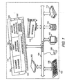
- FIG. 1 shows a block diagram of a computer system incorporating the user interface for scanner software of the present invention.
- computer system 100 contains a processing element 102.
- Processing element 102 communicates with other elements of computer system 100 over a system bus 104.
- a keyboard 106 allows a user to input information into computer system 100 and a monitor 110 allows computer system 100 to output information to the user.
- a graphical input device 108 commonly a mouse, is also used to input information.
- Scanner device 114 is also used to input information to computer system 100.
- Storage device 112 is used to store data and programs within computer system 100.
- Communications interface 116 also connected to system bus 104, receives information from sources outside of computer system 100.
- a memory 118 also attached to system bus 104, contains an operating system 120, window manager 122, and scanner software 124 having the user interface for scanner software of the present invention.
- operating system 120 is the Microsoft Windows ® operating system.
- Memory 118 also contains first software application 126 and second software application 128.
- One skilled in the art will recognize that many more software applications could reside in memory 118. Only two are shown for simplicity.
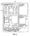
- FIG. 2 shows a representation of the screen display from monitor 110 (FIG. 1) showing the user interface for scanner software 124 (FIG. 1) of the present invention.
- scanner software window 200 shows a variable resolution preview window 202 containing variable resolution preview scan 204 of a document that has been positioned on the flatbed of scanner device 114 (FIG. 1).
- a user initiates a variable resolution preview scan 204 by pressing a preview scan mode button on scanner device 114 (FIG. 1), or through a scan button or pull down menus presented to the user on monitor 110 through scanner software 124, which sends a signal causing scanner device 114 to use a preview scan mode to scan the document.
- a preview scan mode is typically a low resolution scan, dependent on the resolution of the display and the size of the preview window.
- a user may also initiate a zoom scan of an area of the document positioned on the flatbed, in which case the resolution of the data contained in variable resolution preview window 202 may be that of the scanner, which could be a considerably higher resolution than the preview scan mode.
- the data generated from the variable resolution preview scan is displayed as variable resolution preview scan 204 in variable resolution preview window 202.
- Variable resolution preview scan 204 shows regions of various types, including text regions 206, black and white line art regions 208, color photograph regions 210, and gray scale photograph region 212, which is partially superimposed on one of the color photograph regions 210.
- variable resolution preview window 202 is updated with selection marker 216 drawn around the region identified as gray scale photograph region 212.
- selection marker 216 is a rectangular bounding box. The rest of the area of variable resolution preview scan 204 outside of gray scale photograph region 212 is grayed out (not shown in FIG. 2).
- Variable resolution preview window 202 also contains pull down menu bar 218 and tool bar 220, which provide the user with access to various functions of scanner software 124. If no region has been selected, status bar 222 displays information regarding variable resolution preview scan 204 in its entirety. If a region has been selected, as shown in FIG. 2, status bar 222 displays current information regarding the region selected, which in this example is gray scale photograph region 212. Box 224 indicates that the region selected is a gray scale photographic image. Box 226 indicates the image file size is 51.7 KB. A scaling factor of 100% is shown in box 228. A different scaling factor may be displayed if an inter-application communication link, such as TWAIN or OLE, has been established indicating a preferred final size of the region of interest, or if the user has specified one.
- an inter-application communication link such as TWAIN or OLE
- Box 230 indicates that the selected image is measured in inches. The user may also make a "units" preference for Box 230 other than inches, such as centimeters, points, or pixels.
- Box 232 indicates that the selected image is 1.38 inches high, and box 234 indicates that the selected image is 1.74 inches wide. Box 236 indicates a current resolution of 150 dpi.
- Three floating windows are also shown in scanner software window 200 that present control tools to the user.
- the controls reflect adjustments made to variable resolution preview scan 204 based on the contents of the preview window.
- the user may use the tools presented in the floating windows to further manipulate a selected region of interest.
- Exposure adjustment window 238 offers control tools that apply to all photographic output data types to preserve highlight and shadow detail.
- Color adjustment window 240 applies only to color photographic output data types to adjust hue and saturation.
- Black and white threshold window 242 applies only to black and white binary output data types such as line art, clip art, halftones, and text.
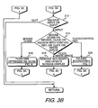
- FIG. 3A and FIG. 3B show a block diagram of the overall flow of the operation of the user interface for scanner software of the present invention.
- the user interface is called from scanner software 124 (FIG. 1), when requested by the user of the scanner software 124.
- Scanner software 124 performs other scanner functions which are not part of the invention.
- variable resolution preview scan 204 (FIG. 2) is displayed within variable resolution preview window 202 (FIG. 2) in monitor 110 (FIG. 1).
- Step 304 determines if click input from graphical input device 108 (FIG. 1) on a region of interest within variable resolution preview scan 204 is received, or if a manual selection is made by clicking in an unselected area and dragging the mouse to create a rectangular selection area, or if an indication to quit the user interface is received. If the latter is true, FIG. 3 returns to scanner software 124. If a manual selection is made, then in step 305 the click and drag input establishing a boundary around a region of interest is received. Then in step 307 scanner software 124 performs classification analysis on the set of data elements contained within the boundary established by step 305, as more fully explained in FIG. 4.
- step 306 click input on a region of interest is received by scanner software 124.
- step 308 calls FIG. 4 which evaluates the region surrounding the click point to determine its boundary and its image data type.
- step 310 calls FIG. 5 to update the screen display of monitor 110.
- step 312 determines if further input, or an indication to quit the user interface, is received. If the latter is true, FIG. 3 returns to scanner software 124. If the former is true, then step 314 determines what type of further input was received. If the input received was a "mouse down" input signal selecting the region of interest for a potential drag and drop from graphical input device 108, then step 316 calls FIG. 6 to potentially perform an optimized final scan of the region of interest. After returning from FIG. 6, control returns to step 304 where another region of interest may be selected, or input received to quit the user interface.
- step 318 scanner software 124 removes selection marker 216 that was placed around the region of interest. This action de-selects the current image selected. All portions of variable resolution preview scan 204 that had been grayed out are restored and the display in variable resolution preview window 202 (FIG. 2) in monitor 110 is updated. Control then returns to step 304 where another region of interest may be selected, or input received to quit the user interface.
- step 320 calls FIG. 7 to re-size the boundary of the region of interest.
- control returns to step 310, which is a call to FIG. 5 to update the screen display of monitor 110.
- FIG. 4 shows a block diagram for determining the boundary of the region of interest and classifying the data type within the region of interest.
- scanner software 124 performs an analysis on the data elements from variable resolution preview scan 204 on the immediate region around the point clicked to determine the boundary of the region of interest and the data type within the region of interest.
- segmentation analysis is performed to determine the boundary of the region of interest.
- Various techniques are well known in the art for performing segmentation analysis, falling into three broad categories: top down strategy (model-driven), bottom up strategy (data-driven), and hybrid.
- extension is performed along a linear front, resulting in a selection marker that is a rectangular bounding box.
- extension is performed along a non-linear front, resulting in a selection marker that is a "lasso" around the region of interest.
- step 402 scanner software 124 perform classification analysis on the set of data elements contained within the boundary established by step 400.
- Various techniques also well known in the art for performing classification analysis, are also disclosed in the two articles cited above.
- the classification method used is that disclosed in Patent NO. 5,596,655 issued to Patricia D. Lopez on January 21, 1997 .
- FIG. 4 Upon completion of classification analysis, FIG. 4 then returns to FIG. 3A.
- FIG. 5 shows a block diagram for updating the computer monitor display based on the selected area and its data type.
- a selection marker is displayed in variable resolution preview scan 204 (FIG. 2) in monitor 110 (FIG. 1) around the region of interest determined from either FIG. 4 or from FIG. 7, which is discussed below. If a selection marker is already displayed when FIG. 5 is called, that selection marker is removed from display before displaying the next selection marker.
- the remainder of variable resolution preview scan 204 lying outside of the region of interest bounded by the currently displayed selection marker is grayed out.
- Step 504 determines the data type of the region of interest. If the data type in the region of interest is text or black and white line art, then control passes to step 506 where scanner software 124 updates the output in black and white threshold window 242 (FIG. 2). In step 508 scanner software 124 updates the resolution, scaling, output dimensions, and file size within status bar 222 (FIG. 2). In step 510 the controls in black and white threshold window 242 (FIG. 2) are enabled for user input. The user may make manual changes using the controls that have been enabled prior to initiating a re-scan of the selected region of interest. In step 512 the controls for exposure adjustment window 238 (FIG. 2) and color adjustment window 240 (FIG. 2) are disabled from user input, and are grayed out.
- steps in steps 506, 508, 510, and 512 automatically make many of the adjustments that the user would normally have to make manually in other prior art scanning systems after selecting an image for scanning.
- the current invention reduces the complexity of the software and confusion of controls that the typical user may not understand.
- the user may also make manual changes using the controls that have been enabled prior to re-scanning the selected image.
- step 504 if the data type in the region of interest is gray scale photographic, then control passes to step 514 where scanner software 124 changes the output in exposure adjustment window 238.
- scanner software 124 updates the resolution, scaling, output dimensions, and file size within status bar 222.
- step 518 the controls in exposure adjustment window 238 are enabled for user input. The user may make manual changes using the controls that have been enabled prior to initiating a re-scan of the selected region of interest.
- step 520 the controls in color adjustment window 240 and black and white threshold window 242 are disabled from user input and are grayed out.
- step 504 if the data type in the region of interest is color photographic, then in step 522 scanner software 124 changes the output in exposure adjustment window 238 and in color adjustment window 240. In step 524 scanner software 124 updates the resolution, scaling, output dimensions, and file size within status bar 222. In step 526 the controls in exposure adjustment window 238 and color adjustment window 240 are enabled for user input. The user may make manual changes using the controls that have been enabled prior to initiating a re-scan of the selected region of interest. In step 528 the controls in black and white threshold window 242 are disabled from user input and is grayed out. After any of steps 512, 520, or 528, FIG. 5 returns to FIG. 3.
- steps in steps 506, 508, 510, and 512; steps 514, 516, 518, and 520; and steps 522, 524, 526, and 528 automatically make many of the adjustments that the user would normally have to make manually in other prior art scanning systems after selecting a region of interest for scanning.
- the current invention reduces the complexity of the software user interface and confusion of controls that the typical user may not understand.
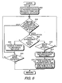
- FIG. 6 shows a block diagram for performing an optimized final scan of the selected region utilizing the drag and drop feature from the Windows operating system.
- a data object is created and a list of one or more predetermined data formats provided in scanner software 124 is loaded into memory, based on the "mouse down" input signal selecting the region of interest displayed in monitor 110 (FIG. 1) whose data type, or classification, was determined in FIG. 4.
- a CF_DIB format is provided, which is a Windows Device Independent Bitmap, and a private drag/drop information format.
- a CF_METAFILEPICT format is provided, which is a Windows Metafile Clipboard format, and a private drag/drop information format.
- a CF_TEXT which is ASCII Text
- a CF_RTF which is Rich Text Format
- the private drag/drop information format is for internal use by scanner software 124 (FIG. 1), mainly as information for drawing feedback when the pointer 214 is moved over scanner software window 200 (FIG. 2).
- CFSTR_FILEDESCRIPTOR CFSTR_FILECONTENTS
- CFSTR_FILEDESCRIPTOR CFSTR_FILECONTENTS
- the user must hold down a control key when the drag operation is initiated in order to add these data formats to the list of formats available to Explorer for a drop to the desktop or to a folder.
- Step 602 determines if a "mouse over" input signal from graphical input device 108, which is handled by operating system 120 (FIG. 1) from a call made by scanner software 124, is received identifying an open application in monitor 110, or identifying scanner software window 200 itself If the "mouse over" input signal is received identifying scanner software window 200, control passes to step 610. Step 610 then determines if a "mouse drop” input signal is received from graphical input device 108 selecting scanner software window 200 displayed in monitor 110. This indicates that the user decided not to initiate an optimized final scan. If the answer is yes, then FIG. 6 returns to FIG. 3. If the answer in step 610 is no, indicating no "mouse drop" signal was received, or that pointer 214 left scanner software window 200, then control returns to step 602.
- step 602 If the "mouse over" input signal in step 602 is received identifying an open application, which was opened by a call to the software application, such as first software application 126 (FIG. 1), then operating system 120 notifies first software application 126 that pointer 214 has entered its window. Then in step 604 first software application 126 queries the list of predetermined data formats associated with the data object created in step 600. If one or more acceptable formats are found in the list generated in step 600, then first software application 126 lets operating system 120 know that it can receive the data and indicates a preferred format from the one or more acceptable formats. Step 612 then determines if a "mouse drop" input signal from graphical input device 108 is received, selecting first software application 126.
- step 612 If the answer is no, indicating no "mouse drop” signal was received, or that pointer 214 has left the first software application 126 window, then control returns to step 602. If the answer in step 612 is yes, indicating that a "mouse drop" input signal was received, then in step 614 first software application 126 makes a call to operating system 120 and requests the image data in the format it prefers. Then, in step 616, scanner software 124 sends a command to scanner 114 (FIG. 1) launching an optimized final scan of the document, and the image data from the optimized final scan is put into the format requested. The image data output from the optimized final scan for the region of interest portion of the document is sent to first software application 126, where the image data resides in the selected data format for further manipulation by the user within first software application 126. Control then returns to FIG. 3.
- step 604 If in step 604 first software application 126 cannot find a format for the data that it can accept from the list generated in step 600, then step 608 changes the displayed pointer 214 to the universal "no" icon, a circle with a diagonal slash through it, indicating that a drop of the data object will not be allowed.
- Step 610 determines if a "mouse drop" input signal is received from graphical input device 108 on first software application 126. If the answer is yes, then FIG. 6 returns to FIG. 3. If the answer in step 610 is no, then control returns to step 602.
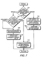
- FIG. 7 shows a block diagram for re-sizing the boundary of a selected area.
- step 700 determines if the click input with graphical input device 108, simultaneous with a control key held down, was received within, or outside of, selection marker 216 (FIG. 2). If the click input was within selection marker 216, indicating that the user wants a smaller area than what was automatically generated in FIG. 4, then step 704 finds a subset of the data elements within selection marker 216 immediately surrounding the click point, and establishes a new, smaller boundary around the subset of data elements. Then, in step 706, scanner software 124 performs classification analysis on the subset of data elements contained within the new boundary established by step 704. FIG. 7 then returns to FIG. 3.
- step 700 determines if the click input with graphical input device 108, simultaneous with a control key held down, was received outside of selection marker 216, indicating that the user wants a larger area than what was automatically generated in FIG. 4, control passes to step 702.
- Step 702 determines if the click input with graphical input device 108, simultaneous with a control key held down, was on white space or non-white space. If the click input was on white space, then step 712 expands the boundary to encompass the entire scanned document. FIG. 7 then returns to FIG. 3.
- step 708 makes an adjustment to the parameters used in the segmentation analysis.
- step 710 calls FIG. 4 to evaluate the data elements surrounding the click point with the new parameters to determine a superset of data elements and a new boundary, and to determine the data type of the superset of data elements within the new boundary. After returning from FIG. 4, FIG. 7 then returns to FIG. 3.
- FIG. 8A and FIG. 8B show a representation of the screen display of a computer monitor showing a screen capture of the user interface for scanner software of the present invention and an open application receiving a scanned image by way of drag and drop input.
- screen display 800 has scanner software window 200 (also shown in FIG. 2) and application software window 802 displayed.
- Variable resolution preview scan 204 is displayed within variable resolution preview window 202 (also shown in FIG. 2).
- Black and white line art region 208 (also shown in FIG. 2) has been selected by a user with graphical input device 108 (FIG. 1) by moving pointer 214 (FIG. 2) to a point within black and white line art region 208, and clicking graphical input device 108, causing selection marker 816 to be displayed around black and white line art region 208.
- Black and white line art region 208 contains black and white line art image 818.
- Status bar 222 (also shown in FIG. 2) is updated to display current information regarding black and white line art region 208.
- the three dialog boxes normally displayed in scanner software window 200 adjacent to variable resolution preview window 202 have been closed down by the user to create room in screen display 800 for application software window 802.
- First software application 126 (FIG. 1) is loaded into memory 118 (FIG. 1) and is displayed in application software window 802, which contains open work area 820.
- First software application 126 may be a word processing application, a spread sheet application, or a photo image editing type application that the user would like to bring a scanned version of black and white line art image 818 into.
- the user moves pointer 214 (not shown in FIGS. 8A and 8B) with graphical input device 108 to a point within black and white line art region 208.
- the user then performs a drag and drop maneuver by holding down the graphical input device button, moving graphical input device 108 such that pointer 214 travels from the point within black and white line art region 208 displayed on monitor 110 that the "mouse down" input signal was sent, to any point within open work area 820 within application software window 802, and then releasing the graphical input device button to send the mouse drop input signal selecting the open application.
- This drag and drop maneuver onto open work area 820 initiates within scanner software 124 (FIG. 1) an optimized final scan of the document, which generates image data.
- the image data is sent from scanner 114 to firsts software application 126, where the image data appears as scanned image 822 in FIG. 8B.
- the image data fully resides within the application software.
- the user may then further manipulate scanned image 822 and/or save the image data to a file.
- variable resolution preview scan 204 If the user selects a text region in variable resolution preview scan 204 to drag and drop to application software window 802, the text region is scanned utilizing the automatic adjustments and updates made by scanner software 124 after the text region was selected. OCR, Optical Character Recognition, is then performed. The resulting data is put into ASCII Text format or Rich Text Format for delivery to the open application.
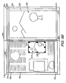
- FIG. 9A and FIG. 9B show a representation of the screen display of a computer monitor showing a screen capture of the user interface for scanner software of the present invention and a desktop receiving a scanned image using the drag and drop feature of the Windows operating system.
- screen display 900 has scanner software window 200 (also shown in FIG. 2) and desktop area 902 displayed.
- Variable resolution preview scan 204 is displayed within variable resolution preview window 202 (also shown in FIG. 2).
- Black and white line art region 208 (also shown in FIG. 2) has been selected by a user with graphical input device 108 (FIG. 1) by moving pointer 214 (FIG. 2) to a point within black and white line art region 208, and clicking graphical input device 108, causing selection marker 816 to be displayed around black and white line art region 208.
- Black and white line art region 208 contains black and white line art image 818.
- Status bar 222 (also shown in FIG. 2) is updated to display current information regarding black and white line art region 208.
- the three floating windows normally displayed in scanner software window 200 adjacent to variable resolution preview window 202 have been closed down by the user to create room in screen display 900 for desktop area 902.
- the user may bring a scanned version of black and white line art image 818 onto desktop area 902.
- the user moves pointer 214 with graphical input device 108 to a point within black and white line art region 208.
- the user then performs a drag and drop maneuver.
- a control key must be held down when the drag operation is initiated to add the data formats to the list of formats available to Explorer for a drop to the desktop or to a folder.
- the graphical input device button is held down, then graphical input device 108 is moved such that pointer 214 (not shown in FIGS 9A or 9B) travels from the "mouse down" point within black and white line art region 208 to any point within desktop area 902, and then the graphical input device button is released, completing the drag and drop maneuver.
- This same procedure may be applied to bring a scanned version of black and white line art image 818 to a writeable folder within a directory window.
- This drag and drop maneuver onto desktop area 902, or onto a writeable folder within a directory window initiates within scanner software 124 (FIG. 1) an optimized final scan of the document which generates image data.
- the image data is sent form scanner 114 to the desktop, which is an open application, where the image data appears in FIG. 8B as scan.bmp icon 904, representing a file created by Explorer, the file manager software in Windows, upon receiving the image data from scanner 114.
- the same icon would appear for a drop to a writeable folder within a directory window.
- the user may then further manipulate the image with a software application that can accept .bmp file formats.
- variable resolution preview scan 204 If the user selects a text region in variable resolution preview scan 204 to drag and drop to desktop area 902, the text region is scanned utilizing the automatic adjustments and updates made by scanner software 124 after the text region was selected. OCR, Optical Character Recognition, is then performed. The resulting data is put into ASCII Text format for delivery to desktop area 902.
- a text file is created by Explorer, the file manager software in Microsoft Windows ®, upon receiving the image data from scanner software 124, and the file appears as an icon in open work area 820, which may be opened by Notepad or whatever other comparable software has been set up by the user.
Landscapes
- Engineering & Computer Science (AREA)
- Multimedia (AREA)
- Signal Processing (AREA)
- User Interface Of Digital Computer (AREA)
- Image Input (AREA)
- Control Of Indicators Other Than Cathode Ray Tubes (AREA)
- Facsimiles In General (AREA)
Claims (10)
- Méthode d'interface utilisateur, dans un système informatique (100), pour transférer des données d'image depuis un logiciel de balayage (124) vers une application logicielle, ladite méthode comprenant:(a) le lancement (300) d'un balayage d'aperçu d'un document, avec ledit logiciel de balayage (124) chargé dans une mémoire (118) d'un système informatique (100), créant des données de balayage d'aperçu dudit document ;(b) l'affichage (302) desdites données de balayage d'aperçu sur un moniteur (110) connecté au dit système informatique (100) ;(c) la sélection d'une zone d'intérêt à partir desdites données de balayage d'aperçu affichées sur ledit moniteur (110) ;(d) la réalisation d'une analyse de classification (402) sur des éléments de données contenus dans la zone d'intérêt provenant desdites données de balayage d'aperçu pour déterminer un type de données d'image desdits éléments de données ;(e) l'actualisation automatique des informations concernant la zone d'intérêt sélectionnée et l'activation d'outils d'ajustement basée sur le type de données d'image ;(f) le lancement (616), avec ledit logiciel de balayage (124) d'un balayage final dudit document créant lesdites données d'image, dans lequel lesdites données d'image dudit document correspondent à ladite zone d'intérêt sélectionnée.
- Méthode d'interface utilisateur, dans un système informatique (100), pour transférer des données depuis un logiciel de balayage (124) vers une application logicielle selon la revendication 1, dans laquelle l'étape (a) comprend en outre l'étape (a0), et l'étape (f) comprend en outre l'étape (f1) :(a0) le placement dudit document dans une position à balayer par un dispositif de balayage (114) connecté au dit système informatique (100) ; et(f1) la réception dans ledit dispositif de balayage (114), depuis ledit logiciel de balayage (124) d'une commande pour lancer ledit balayage final dudit document, dans laquelle ledit balayage final crée lesdites données d'image.
- Méthode d'interface utilisateur, dans un système informatique (100), pour transférer des données depuis un logiciel de balayage (124) vers une application logicielle selon la revendication 1, dans laquelle l'étape (d) comprend en outre les étapes (d1) et (d2) :(d1) la réception (600) d'un type de données pour ladite zone d'intérêt sélectionnée dans ladite mémoire (118) dans ledit système informatique (100) ; et(d2) l'extraction (616) d'au moins un format de données associé au dit type de données pour ladite zone d'intérêt sélectionnée.
- Méthode d'interface utilisateur, dans un système informatique (100), pour transférer des données depuis un logiciel de balayage (124) vers une application logicielle selon la revendication 3, dans laquelle lorsque ledit type de données pour ladite zone d'intérêt sélectionnée est un type couleur réelle, échelle de gris, palette ou binaire noir et blanc, ledit format de données est un format Windows Device Independent Bitmap.
- Méthode d'interface utilisateur, dans un système informatique (100), pour transférer des données depuis un logiciel de balayage (124) vers une application logicielle selon la revendication 3, dans laquelle lorsque ledit type de données pour ladite zone d'intérêt sélectionnée est un vecteur scalaire noir et blanc, ledit format de données est un format Windows Metafile Clipboard.
- Méthode d'interface utilisateur, dans un système informatique (100), pour transférer des données depuis un logiciel de balayage (124) vers une application logicielle selon la revendication 3, dans laquelle lorsque ledit type de données pour ladite zone d'intérêt sélectionnée est un texte, ledit format de données est un format ASCII Text ou un format Rich Text.
- Méthode d'interface utilisateur, dans un système informatique (100), pour transférer des données depuis un logiciel de balayage (124) vers une application logicielle selon la revendication 3, dans laquelle l'étape (e) comprend en outre les étapes suivantes (e0a), (e0b) et (e1), l'étape (e1) étant réalisée après les étapes (e0a) et (e0b), et l'étape (g) comprend en outre l'étape (g0):(e0a) la réception (602) d'un signal d'entrée « souris au-dessus » provenant dudit dispositif d'entrée graphique (108) identifiant ladite application logicielle affichée sur ledit moniteur (110) ;(e0b) la demande (604) par ladite application logicielle si ledit logiciel de balayage (124) offre l'un desdits au moins un format de données associé au dit type de données de ladite zone d'intérêt sélectionnée, dans laquelle ladite application logicielle peut accepter une insertion dudit type de données formaté dans ledit un desdits au moins un format de données associé au dit type de données ;(e1) la demande (614), par ladite application logicielle, que lesdites données d'image soient formatées dans l'un desdits au moins un format de données associé au dit type de données que l'application logicielle peut accepter ; et(g0) le formatage (616) desdites données d'image dans ledit un desdits au moins un format de données associé au dit type de données que ladite application logicielle peut accepter.
- Méthode d'interface utilisateur, dans un système informatique (100), pour transférer des données depuis un logiciel de balayage (124) vers une application logicielle selon la revendication 1, comprenant en outre les étapes consistant en :(i) la réception (616) desdites données d'image dans ladite application logicielle sélectionnée dans ladite mémoire (118) ; et(ii) l'affichage (616) desdites données d'image dans ladite fenêtre d'application ouverte (802) sur ledit moniteur (110).
- Méthode d'interface utilisateur, dans un système informatique (100), pour transférer des données depuis un logiciel de balayage (124) vers une application logicielle selon la revendication 8, dans laquelle ladite application logicielle est une zone de bureau (902) et dans laquelle l'étape (i) comprend en outre les étapes (i1) à (i3) :(i1) la création d'un fichier, par un logiciel de gestion des fichiers dans un système d'exploitation chargé dans ladite mémoire (118), à réception desdites données d'image dans ladite mémoire (118), dans laquelle un type de fichier dudit fichier est déterminé en fonction dudit type de données ;(i2) la sauvegarde dudit fichier en tant que dit type de fichier dans ledit système informatique (100) ; et(i3) l'affichage d'une représentation dudit fichier dudit type de fichier en tant qu'icône sur ladite zone de bureau (902).
- Méthode d'interface utilisateur, dans un système informatique (100), pour transférer des données depuis un logiciel de balayage (124) vers une application logicielle selon la revendication 8, dans laquelle ladite application logicielle est un dossier inscriptible et dans laquelle l'étape (i) comprend en outre les étapes (i1) à (i3) :(i1) la création d'un fichier, par un logiciel de gestion des fichiers dans un système d'exploitation chargé dans ladite mémoire (118), à réception desdites données d'image dans ladite mémoire (118), dans laquelle un type dudit fichier est déterminé en fonction dudit type de données ;(i2) la sauvegarde dudit fichier en tant que dit type de fichier dans ledit système informatique (100) ; et(i3) l'affichage d'une représentation dudit fichier en tant qu'icône sur ledit dossier inscriptible.
Applications Claiming Priority (2)
| Application Number | Priority Date | Filing Date | Title |
|---|---|---|---|
| US164795 | 1998-10-01 | ||
| US09/164,795 US6751780B1 (en) | 1998-10-01 | 1998-10-01 | User interface for initiating the export of an optimized scanned document using drag and drop |
Publications (3)
| Publication Number | Publication Date |
|---|---|
| EP0991263A2 EP0991263A2 (fr) | 2000-04-05 |
| EP0991263A3 EP0991263A3 (fr) | 2003-08-13 |
| EP0991263B1 true EP0991263B1 (fr) | 2007-10-17 |
Family
ID=22596128
Family Applications (1)
| Application Number | Title | Priority Date | Filing Date |
|---|---|---|---|
| EP99115483A Expired - Lifetime EP0991263B1 (fr) | 1998-10-01 | 1999-08-05 | Interface utilsateur pour déclencher un balayage final utilisant déclenchement et lâchage |
Country Status (4)
| Country | Link |
|---|---|
| US (2) | US6751780B1 (fr) |
| EP (1) | EP0991263B1 (fr) |
| JP (1) | JP2000113180A (fr) |
| DE (1) | DE69937327T2 (fr) |
Families Citing this family (68)
| Publication number | Priority date | Publication date | Assignee | Title |
|---|---|---|---|---|
| AUPQ291299A0 (en) * | 1999-09-17 | 1999-10-07 | Silverbrook Research Pty Ltd | A self mapping surface and related applications |
| TW424385B (en) * | 1999-08-18 | 2001-03-01 | Umax Data Systems Inc | The execution method at man-machine interface of scanners and the system to which it applies |
| US6628416B1 (en) | 1999-10-13 | 2003-09-30 | Umax Data Systems, Inc. | Method and user interface for performing a scan operation for a scanner coupled to a computer system |
| JP4725876B2 (ja) * | 2000-06-08 | 2011-07-13 | 俊彦 岡部 | データ引き渡し装置 |
| US20020116420A1 (en) * | 2000-09-28 | 2002-08-22 | Allam Scott Gerald | Method and apparatus for displaying and viewing electronic information |
| US7869067B2 (en) * | 2000-10-20 | 2011-01-11 | Visioneer, Inc. | Combination scanner and image data reader system including image management and software |
| US7574664B2 (en) * | 2001-02-15 | 2009-08-11 | Nbor Corporation | Methods for recursive spacing and touch transparency of onscreen objects |
| US7630574B2 (en) * | 2001-06-06 | 2009-12-08 | Sharp Kabushiki Kaisha | Image encoding method and image apparatus |
| US6992789B2 (en) * | 2001-06-15 | 2006-01-31 | International Business Machines Corporation | Method, system, and program for managing a multi-page document |
| US7110152B2 (en) * | 2001-08-31 | 2006-09-19 | Hewlett-Packard Development Company, L.P. | Virtual scanning from a scanned image preview |
| US7440146B2 (en) * | 2001-09-20 | 2008-10-21 | Transpacific Ip, Llp | Scanning method and scanning system free of identifying original's attribute |
| US7212316B2 (en) | 2001-12-19 | 2007-05-01 | Wen-Yung Huang | Method for automatically identifying scan area |
| US7395503B1 (en) | 2002-02-06 | 2008-07-01 | Adobe Systems Incorporated | Dynamic preview of electronic signature appearance |
| US20030187735A1 (en) * | 2002-04-01 | 2003-10-02 | Pierre Dewis Francois Olivier | Life-cycle -based pre-emptive electronic mail generator |
| US20040216149A1 (en) * | 2002-07-16 | 2004-10-28 | Reitz Larry E. | Content exporting from one application to another |
| US20040015539A1 (en) * | 2002-07-16 | 2004-01-22 | Andrew Alegria | Content exporting from one application to another |
| US7966569B2 (en) * | 2002-08-16 | 2011-06-21 | Schlumberger Technology Corporation | Method and system and program storage device for storing oilfield related data in a computer database and displaying a field data handbook on a computer display screen |
| US20040139400A1 (en) * | 2002-10-23 | 2004-07-15 | Allam Scott Gerald | Method and apparatus for displaying and viewing information |
| JP4412701B2 (ja) | 2003-01-24 | 2010-02-10 | 日本電気株式会社 | 画面情報表示方法、システム及びコンピュータプログラム |
| US20040169873A1 (en) * | 2003-02-28 | 2004-09-02 | Xerox Corporation | Automatic determination of custom parameters based on scanned image data |
| CA2433527A1 (fr) * | 2003-06-26 | 2004-12-26 | Ibm Canada Limited - Ibm Canada Limitee | Systeme et methode pour interpreteur de commandes integre graphique et oriente objet |
| US7424672B2 (en) * | 2003-10-03 | 2008-09-09 | Hewlett-Packard Development Company, L.P. | System and method of specifying image document layout definition |
| US7822233B2 (en) | 2003-11-14 | 2010-10-26 | Fujifilm Corporation | Method and apparatus for organizing digital media based on face recognition |
| KR100601676B1 (ko) | 2004-05-12 | 2006-07-14 | 삼성전자주식회사 | 편집기능을 갖는 문서 스캔 방법 및 장치 및 그를 이용한복합기 |
| US7856441B1 (en) | 2005-01-10 | 2010-12-21 | Yahoo! Inc. | Search systems and methods using enhanced contextual queries |
| US7421441B1 (en) * | 2005-09-20 | 2008-09-02 | Yahoo! Inc. | Systems and methods for presenting information based on publisher-selected labels |
| US7603349B1 (en) * | 2004-07-29 | 2009-10-13 | Yahoo! Inc. | User interfaces for search systems using in-line contextual queries |
| US7409402B1 (en) * | 2005-09-20 | 2008-08-05 | Yahoo! Inc. | Systems and methods for presenting advertising content based on publisher-selected labels |
| US8972856B2 (en) * | 2004-07-29 | 2015-03-03 | Yahoo! Inc. | Document modification by a client-side application |
| KR100615701B1 (ko) * | 2004-11-18 | 2006-08-25 | 삼성전자주식회사 | 스캔이미지 미리보기 기능을 구비한 화상형성시스템 및 그방법 |
| JP4016996B2 (ja) * | 2005-04-19 | 2007-12-05 | コニカミノルタビジネステクノロジーズ株式会社 | 画像処理システム、画像処理装置、および画像処理プログラム |
| US7890881B1 (en) * | 2005-07-29 | 2011-02-15 | Adobe Systems Incorporated | Systems and methods for a fold preview |
| US20070033540A1 (en) * | 2005-08-05 | 2007-02-08 | Lexmark International, Inc. | Systems and methods for directory and file manipulation using a multifunction device |
| JP4001158B2 (ja) * | 2005-08-08 | 2007-10-31 | コニカミノルタビジネステクノロジーズ株式会社 | ボックスデータ管理装置及び方法 |
| JP4687425B2 (ja) | 2005-11-25 | 2011-05-25 | 富士ゼロックス株式会社 | 画像読取装置および制御方法 |
| US20070130183A1 (en) * | 2005-12-01 | 2007-06-07 | Morris Robert P | Methods, systems, and computer program products for associating computer-system-accessible resources using behaviors |
| US8607147B2 (en) * | 2005-12-09 | 2013-12-10 | International Business Machines Corporation | System and methods for previewing alternative compositions and arrangements when composing a strictly-structured flow diagram |
| JP4702947B2 (ja) * | 2006-02-02 | 2011-06-15 | キヤノン株式会社 | コード情報の印刷装置、印刷方法、復元装置、復元方法およびコンピュータプログラム |
| US7844898B2 (en) * | 2006-02-28 | 2010-11-30 | Microsoft Corporation | Exporting a document in multiple formats |
| JP4270262B2 (ja) * | 2006-10-06 | 2009-05-27 | セイコーエプソン株式会社 | 複合機及び印刷システム |
| US8739068B2 (en) * | 2007-06-15 | 2014-05-27 | Microsoft Corporation | Dynamic user interface for in-diagram shape selection |
| US8023716B2 (en) * | 2007-10-26 | 2011-09-20 | Bank Of America Corporation | Synchronization of image capture settings |
| US20090122018A1 (en) * | 2007-11-12 | 2009-05-14 | Leonid Vymenets | User Interface for Touchscreen Device |
| US8762871B2 (en) * | 2008-02-03 | 2014-06-24 | Microsoft Corporation | Dynamic preview of diagram elements to be inserted into a diagram |
| US8650634B2 (en) * | 2009-01-14 | 2014-02-11 | International Business Machines Corporation | Enabling access to a subset of data |
| JP5462557B2 (ja) * | 2009-09-03 | 2014-04-02 | キヤノン株式会社 | 画像処理装置及びその制御方法 |
| US8610924B2 (en) * | 2009-11-24 | 2013-12-17 | International Business Machines Corporation | Scanning and capturing digital images using layer detection |
| US8441702B2 (en) * | 2009-11-24 | 2013-05-14 | International Business Machines Corporation | Scanning and capturing digital images using residue detection |
| US20110122459A1 (en) * | 2009-11-24 | 2011-05-26 | International Business Machines Corporation | Scanning and Capturing digital Images Using Document Characteristics Detection |
| US9779168B2 (en) | 2010-10-04 | 2017-10-03 | Excalibur Ip, Llc | Contextual quick-picks |
| US9110743B2 (en) * | 2010-12-21 | 2015-08-18 | Microsoft Technology Licensing, Llc | Extensible system action for sharing while remaining in context |
| TW201242333A (en) * | 2011-04-06 | 2012-10-16 | Hon Hai Prec Ind Co Ltd | Image processing apparatus and method for controlling image processing apparatus |
| EP2538654A1 (fr) * | 2011-06-22 | 2012-12-26 | LG Electronics | Technologie de balayage |
| KR101809750B1 (ko) * | 2011-06-22 | 2018-01-18 | 엘지전자 주식회사 | 스캔 이미지 편집 방법, 이의 표시기기 |
| EP2549735A3 (fr) * | 2011-07-19 | 2014-08-27 | Samsung Electronics Co., Ltd. | Procédé d'édition d'images combinées numériques statiques comprenant des images de plusieurs objets |
| US8775947B2 (en) | 2011-08-11 | 2014-07-08 | International Business Machines Corporation | Data sharing software program utilizing a drag-and-drop operation and spring-loaded portal |
| US9110595B2 (en) | 2012-02-28 | 2015-08-18 | AVG Netherlands B.V. | Systems and methods for enhancing performance of software applications |
| CN103970456A (zh) * | 2013-01-28 | 2014-08-06 | 财付通支付科技有限公司 | 一种智能终端的交互方法和装置 |
| US20140282209A1 (en) * | 2013-03-15 | 2014-09-18 | Logitech Europe S.A. | Method for activating an application bar |
| US20160026613A1 (en) * | 2014-07-28 | 2016-01-28 | Microsoft Corporation | Processing image to identify object for insertion into document |
| JP6647524B2 (ja) * | 2015-10-27 | 2020-02-14 | 北陽電機株式会社 | エリアセンサ及び外部記憶装置 |
| CN105898481A (zh) * | 2015-11-30 | 2016-08-24 | 乐视网信息技术(北京)股份有限公司 | 终端设备的操作方法和终端设备 |
| JP6269699B2 (ja) * | 2016-02-19 | 2018-01-31 | 株式会社リコー | 画像処理装置、プログラム、画像処理方法 |
| US11857358B2 (en) | 2018-09-28 | 2024-01-02 | Hologic, Inc. | System and method for synthetic breast tissue image generation by high density element suppression |
| US12170140B2 (en) * | 2018-11-25 | 2024-12-17 | Hologic, Inc. | Customizable multimodality image hanging protocols |
| CN113574609A (zh) | 2019-03-29 | 2021-10-29 | 豪洛捷公司 | 剪切触发的数字图像报告生成 |
| JP7404902B2 (ja) * | 2020-01-31 | 2023-12-26 | ブラザー工業株式会社 | プログラム、情報処理装置及び情報処理方法 |
| US12186119B2 (en) | 2021-10-05 | 2025-01-07 | Hologic, Inc. | Interactive model interface for image selection in medical imaging systems |
Family Cites Families (12)
| Publication number | Priority date | Publication date | Assignee | Title |
|---|---|---|---|---|
| JPH0652472B2 (ja) * | 1984-07-23 | 1994-07-06 | インターナショナル・ビジネス・マシーンズ・コーポレーション | イメージ処理方法 |
| US4837635A (en) * | 1988-01-22 | 1989-06-06 | Hewlett-Packard Company | A scanning system in which a portion of a preview scan image of a picture displaced on a screen is selected and a corresponding portion of the picture is scanned in a final scan |
| US5596655A (en) | 1992-08-18 | 1997-01-21 | Hewlett-Packard Company | Method for finding and classifying scanned information |
| US6134017A (en) * | 1994-11-14 | 2000-10-17 | Canon Kabushiki Kaisha | Facsimile manager |
| US5732230A (en) * | 1995-05-19 | 1998-03-24 | Richo Company Ltd. | Computer user interface for manipulating image fragments using drag, drop and merge operations |
| US6188807B1 (en) * | 1995-10-04 | 2001-02-13 | Canon Kabushiki Kaisha | Scanner server apparatus and scanner server system |
| EP0767578B1 (fr) * | 1995-10-04 | 2002-04-10 | Canon Kabushiki Kaisha | Procédé de traitement d'images |
| US5907665A (en) * | 1995-10-11 | 1999-05-25 | Hewlett-Packard Company | Method and apparatus for transforming image data |
| US5872569A (en) * | 1995-10-30 | 1999-02-16 | Xerox Corporation | Apparatus and method for programming and/or controlling output of a job in a document processing system |
| US5960448A (en) * | 1995-12-15 | 1999-09-28 | Legal Video Services Inc. | System and method for displaying a graphically enhanced view of a region of a document image in which the enhanced view is correlated with text derived from the document image |
| US6295388B1 (en) * | 1996-06-10 | 2001-09-25 | Agfa Corporation | Method for selecting an area of full resolution image detail for viewing during scanning |
| JPH10143347A (ja) * | 1996-11-06 | 1998-05-29 | Sharp Corp | データ転送の表示および操作方法 |
-
1998
- 1998-10-01 US US09/164,795 patent/US6751780B1/en not_active Expired - Fee Related
-
1999
- 1999-08-05 EP EP99115483A patent/EP0991263B1/fr not_active Expired - Lifetime
- 1999-08-05 DE DE69937327T patent/DE69937327T2/de not_active Expired - Lifetime
- 1999-09-30 JP JP27964299A patent/JP2000113180A/ja active Pending
-
2004
- 2004-05-19 US US10/848,846 patent/US20040212835A1/en not_active Abandoned
Also Published As
| Publication number | Publication date |
|---|---|
| DE69937327T2 (de) | 2008-05-15 |
| EP0991263A2 (fr) | 2000-04-05 |
| EP0991263A3 (fr) | 2003-08-13 |
| DE69937327D1 (de) | 2007-11-29 |
| JP2000113180A (ja) | 2000-04-21 |
| US20040212835A1 (en) | 2004-10-28 |
| US6751780B1 (en) | 2004-06-15 |
Similar Documents
| Publication | Publication Date | Title |
|---|---|---|
| EP0991263B1 (fr) | Interface utilsateur pour déclencher un balayage final utilisant déclenchement et lâchage | |
| US6151426A (en) | Click and select user interface for document scanning | |
| US6590584B1 (en) | Image editing method and apparatus | |
| US6202073B1 (en) | Document editing system and method | |
| US6850259B1 (en) | Systems and methods for providing original document orientation, tone reproduction curves and task specific user instructions based on displayed portions of a graphical user interface | |
| US8139256B2 (en) | Method and system for merging scan files into a color workflow | |
| DE69937029T2 (de) | Signalverarbeitungsverfahren und Vorrichtung für Grauskala-Videosignal in einer Matrix-Anzeigevorrichtung | |
| US7065716B1 (en) | Systems, methods and graphical user interfaces for previewing image capture device output results | |
| US6741270B1 (en) | Systems and methods scaling a captured image using predetermined scale information | |
| US20030197894A1 (en) | Method and apparatus for processing an image, and storage medium | |
| US20050270601A1 (en) | Systems, methods and graphical user interfaces for interactively previewing a scanned document | |
| US5422743A (en) | Operator invoked document defect repair templates | |
| AU2001286981A1 (en) | Method and system for merging scan files into a color workflow | |
| EP1128659A1 (fr) | Interface utilisateur graphique de previsualisation de données d'image de document à double face ou reliés | |
| US20090080000A1 (en) | Information processing apparatus, information processing method, and program and storage medium therefor | |
| US7382919B2 (en) | System and method for editing image data | |
| JPH0877330A (ja) | 画像処理方法及び装置 | |
| US20010025326A1 (en) | System, device, and method for inputting image, and storage medium therefor | |
| US20050237573A1 (en) | Image processing apparatus and method | |
| JPH11316821A (ja) | 情報処理方法及び装置 | |
| US6976223B1 (en) | Method and system to establish dedicated interfaces for the manipulation of segmented images | |
| JP2000224414A (ja) | 情報処理システム及びその制御方法、情報処理装置及びその制御方法、コンピュータ可読メモリ | |
| EP0991265A2 (fr) | Fonction de surlignage dans une interface utilisateur pour obtenir une entrée dirigée pour le traitement d'images | |
| JP3890096B2 (ja) | 画像編集システム | |
| EP0783149A1 (fr) | Presse-papier pour système de bureau interactif |
Legal Events
| Date | Code | Title | Description |
|---|---|---|---|
| PUAI | Public reference made under article 153(3) epc to a published international application that has entered the european phase |
Free format text: ORIGINAL CODE: 0009012 |
|
| AK | Designated contracting states |
Kind code of ref document: A2 Designated state(s): AT BE CH CY DE DK ES FI FR GB GR IE IT LI LU MC NL PT SE |
|
| AX | Request for extension of the european patent |
Free format text: AL;LT;LV;MK;RO;SI |
|
| RAP1 | Party data changed (applicant data changed or rights of an application transferred) |
Owner name: HEWLETT-PACKARD COMPANY, A DELAWARE CORPORATION |
|
| PUAL | Search report despatched |
Free format text: ORIGINAL CODE: 0009013 |
|
| AK | Designated contracting states |
Designated state(s): AT BE CH CY DE DK ES FI FR GB GR IE IT LI LU MC NL PT SE |
|
| AX | Request for extension of the european patent |
Extension state: AL LT LV MK RO SI |
|
| 17P | Request for examination filed |
Effective date: 20030923 |
|
| AKX | Designation fees paid |
Designated state(s): DE FR GB |
|
| 17Q | First examination report despatched |
Effective date: 20040701 |
|
| GRAP | Despatch of communication of intention to grant a patent |
Free format text: ORIGINAL CODE: EPIDOSNIGR1 |
|
| GRAS | Grant fee paid |
Free format text: ORIGINAL CODE: EPIDOSNIGR3 |
|
| GRAA | (expected) grant |
Free format text: ORIGINAL CODE: 0009210 |
|
| AK | Designated contracting states |
Kind code of ref document: B1 Designated state(s): DE FR GB |
|
| REG | Reference to a national code |
Ref country code: GB Ref legal event code: FG4D |
|
| REF | Corresponds to: |
Ref document number: 69937327 Country of ref document: DE Date of ref document: 20071129 Kind code of ref document: P |
|
| EN | Fr: translation not filed | ||
| PLBE | No opposition filed within time limit |
Free format text: ORIGINAL CODE: 0009261 |
|
| STAA | Information on the status of an ep patent application or granted ep patent |
Free format text: STATUS: NO OPPOSITION FILED WITHIN TIME LIMIT |
|
| 26N | No opposition filed |
Effective date: 20080718 |
|
| PG25 | Lapsed in a contracting state [announced via postgrant information from national office to epo] |
Ref country code: FR Free format text: LAPSE BECAUSE OF FAILURE TO SUBMIT A TRANSLATION OF THE DESCRIPTION OR TO PAY THE FEE WITHIN THE PRESCRIBED TIME-LIMIT Effective date: 20080801 |
|
| REG | Reference to a national code |
Ref country code: GB Ref legal event code: 732E Free format text: REGISTERED BETWEEN 20120329 AND 20120404 |
|
| PGFP | Annual fee paid to national office [announced via postgrant information from national office to epo] |
Ref country code: DE Payment date: 20140722 Year of fee payment: 16 |
|
| PGFP | Annual fee paid to national office [announced via postgrant information from national office to epo] |
Ref country code: GB Payment date: 20140725 Year of fee payment: 16 |
|
| REG | Reference to a national code |
Ref country code: DE Ref legal event code: R119 Ref document number: 69937327 Country of ref document: DE |
|
| GBPC | Gb: european patent ceased through non-payment of renewal fee |
Effective date: 20150805 |
|
| PG25 | Lapsed in a contracting state [announced via postgrant information from national office to epo] |
Ref country code: GB Free format text: LAPSE BECAUSE OF NON-PAYMENT OF DUE FEES Effective date: 20150805 Ref country code: DE Free format text: LAPSE BECAUSE OF NON-PAYMENT OF DUE FEES Effective date: 20160301 |