EP0992100B1 - Einrichtung und methode für die verwaltung einer batterienotstromversorgungseinrichtung - Google Patents
Einrichtung und methode für die verwaltung einer batterienotstromversorgungseinrichtung Download PDFInfo
- Publication number
- EP0992100B1 EP0992100B1 EP98931856A EP98931856A EP0992100B1 EP 0992100 B1 EP0992100 B1 EP 0992100B1 EP 98931856 A EP98931856 A EP 98931856A EP 98931856 A EP98931856 A EP 98931856A EP 0992100 B1 EP0992100 B1 EP 0992100B1
- Authority
- EP
- European Patent Office
- Prior art keywords
- battery
- module
- battery module
- battery pack
- capacity
- Prior art date
- Legal status (The legal status is an assumption and is not a legal conclusion. Google has not performed a legal analysis and makes no representation as to the accuracy of the status listed.)
- Expired - Lifetime
Links
Images


Classifications
-
- H—ELECTRICITY
- H02—GENERATION; CONVERSION OR DISTRIBUTION OF ELECTRIC POWER
- H02J—ELECTRIC POWER NETWORKS; CIRCUIT ARRANGEMENTS OR SYSTEMS FOR SUPPLYING OR DISTRIBUTING ELECTRIC POWER; SYSTEMS FOR STORING ELECTRIC ENERGY
- H02J7/00—Circuit arrangements for charging or discharging batteries or for supplying loads from batteries
- H02J7/50—Circuit arrangements for charging or discharging batteries or for supplying loads from batteries acting upon multiple batteries simultaneously or sequentially
- H02J7/52—Circuit arrangements for charging or discharging batteries or for supplying loads from batteries acting upon multiple batteries simultaneously or sequentially for charge balancing, e.g. equalisation of charge between batteries
- H02J7/56—Active balancing, e.g. using capacitor-based, inductor-based or DC-DC converters
-
- G—PHYSICS
- G01—MEASURING; TESTING
- G01R—MEASURING ELECTRIC VARIABLES; MEASURING MAGNETIC VARIABLES
- G01R31/00—Arrangements for testing electric properties; Arrangements for locating electric faults; Arrangements for electrical testing characterised by what is being tested not provided for elsewhere
- G01R31/36—Arrangements for testing, measuring or monitoring the electrical condition of accumulators or electric batteries, e.g. capacity or state of charge [SoC]
- G01R31/392—Determining battery ageing or deterioration, e.g. state of health
-
- G—PHYSICS
- G01—MEASURING; TESTING
- G01R—MEASURING ELECTRIC VARIABLES; MEASURING MAGNETIC VARIABLES
- G01R31/00—Arrangements for testing electric properties; Arrangements for locating electric faults; Arrangements for electrical testing characterised by what is being tested not provided for elsewhere
- G01R31/36—Arrangements for testing, measuring or monitoring the electrical condition of accumulators or electric batteries, e.g. capacity or state of charge [SoC]
- G01R31/396—Acquisition or processing of data for testing or for monitoring individual cells or groups of cells within a battery
-
- H—ELECTRICITY
- H02—GENERATION; CONVERSION OR DISTRIBUTION OF ELECTRIC POWER
- H02J—ELECTRIC POWER NETWORKS; CIRCUIT ARRANGEMENTS OR SYSTEMS FOR SUPPLYING OR DISTRIBUTING ELECTRIC POWER; SYSTEMS FOR STORING ELECTRIC ENERGY
- H02J7/00—Circuit arrangements for charging or discharging batteries or for supplying loads from batteries
- H02J7/50—Circuit arrangements for charging or discharging batteries or for supplying loads from batteries acting upon multiple batteries simultaneously or sequentially
-
- H—ELECTRICITY
- H02—GENERATION; CONVERSION OR DISTRIBUTION OF ELECTRIC POWER
- H02J—ELECTRIC POWER NETWORKS; CIRCUIT ARRANGEMENTS OR SYSTEMS FOR SUPPLYING OR DISTRIBUTING ELECTRIC POWER; SYSTEMS FOR STORING ELECTRIC ENERGY
- H02J7/00—Circuit arrangements for charging or discharging batteries or for supplying loads from batteries
- H02J7/80—Circuit arrangements for charging or discharging batteries or for supplying loads from batteries including monitoring or indicating arrangements
- H02J7/82—Control of state of charge [SOC]
-
- H—ELECTRICITY
- H02—GENERATION; CONVERSION OR DISTRIBUTION OF ELECTRIC POWER
- H02J—ELECTRIC POWER NETWORKS; CIRCUIT ARRANGEMENTS OR SYSTEMS FOR SUPPLYING OR DISTRIBUTING ELECTRIC POWER; SYSTEMS FOR STORING ELECTRIC ENERGY
- H02J7/00—Circuit arrangements for charging or discharging batteries or for supplying loads from batteries
- H02J7/80—Circuit arrangements for charging or discharging batteries or for supplying loads from batteries including monitoring or indicating arrangements
- H02J7/84—Control of state of health [SOH]
-
- Y—GENERAL TAGGING OF NEW TECHNOLOGICAL DEVELOPMENTS; GENERAL TAGGING OF CROSS-SECTIONAL TECHNOLOGIES SPANNING OVER SEVERAL SECTIONS OF THE IPC; TECHNICAL SUBJECTS COVERED BY FORMER USPC CROSS-REFERENCE ART COLLECTIONS [XRACs] AND DIGESTS
- Y02—TECHNOLOGIES OR APPLICATIONS FOR MITIGATION OR ADAPTATION AGAINST CLIMATE CHANGE
- Y02T—CLIMATE CHANGE MITIGATION TECHNOLOGIES RELATED TO TRANSPORTATION
- Y02T10/00—Road transport of goods or passengers
- Y02T10/60—Other road transportation technologies with climate change mitigation effect
- Y02T10/70—Energy storage systems for electromobility, e.g. batteries
Definitions
- the present invention relates to a system and method for the management of a battery pack used as a power back-up for an A.C. power source.
- the invention has particular application to distributed telecommunication systems and enables the useful capacity and health of a back-up battery power source of one or more of the links in the telecom system to be monitored, assessed and managed from a remote location.
- the invention may be used in conjunction with any device or network of devices which is battery-powered, or which uses a battery pack as an alternative or back-up power source, such as telecommunication relay sites, fibre optic sites, computers; telecommunication or station batteries; telephone switching facilities and portable test equipment.
- US Patent 5,153,496 issued to LaForge discloses a cell monitoring and control circuit for a multicell battery.
- the circuit comprises a cell access switch coupled to the cells of the battery for electronically accessing individual cells of the battery.
- the circuit also includes a monitoring and control circuit coupled to the cell access switch for electronic communication with the cells.
- the circuit is coupled to the battery for providing electric power and constitutes an insignificant current drain on the battery.
- the circuit senses the voltage state of each cell and controls the charging of each cell and provides End-of-Discharge and End-of-Charge signals.
- US Patent 5,543,245 issued to Andrieu et al.
- This patent discloses a system for monitoring aging of a battery comprising a plurality of cells connected in series and able to be fully discharged.
- the system comprises a plurality or dischargers which discharge respective ones of the previously charged cells to an end of discharge value.
- the quantity of electricity supplied by at least one discharged cell is processed to detect excessive aging of the battery. Excessive aging of the battery results in a residual capacity which is less than a fraction of the nominal capacity of the battery.
- the present invention obviates and mitigates the disadvantages inherent in the prior art by providing a system according to claim 1 as well as a method according to claim 10 for directly assessing the useful capacity of a back-up battery, even where the battery is located at a remote site and without compromising the ability of the back-up battery to operate should there be an AC power failure during the battery testing.
- module means one or more electrochemical cells.
- a further advantage of the present invention arises from its capability to rejuvenate or boost the health of the battery module of certain chemistries, e.g. valve regulated lead acid (VRLA) or nickel/cadmium.
- the discharge/charge sequence which is carried out in order to assess and monitor the useful capacity of the module, also serves to better cycle the module.
- the method according to the present invention enables managing the back-up, battery power source of the distributed communications systems of the telecommunications industry.
- the invention enables individual telecom sites with fibre optic or radio equipment powered by systems containing back-up batteries to be operated with improved reliability and economy.
- the invention provides smart charging at the cell or module level, thus ensuring that the back-up battery pack always receives optimum charging.
- the invention further provides a continuously updated battery pack capacity based on cell or module discharge tests so that the individual sites on the telecom system are provided with a real time method of back-up battery network management.
- This network battery management system provides the user with information to optimize the efficiency and operability of the telecom system, in case of AC power failure, particularly if there is a widespread or prolonged AC power outage.
- the invention provides a system
- the programmable logic controller comprises, or is operatively connected to at least one module voltage reader; battery pack current reader and module current reader; a switch controller to control said isolation relays; a controller for said variable discharge load means and said single module battery charger (charger/discharger controller).
- the invention provides a method of sequentially assessing the operating capacity or useful capacity of a plurality of battery modules which define a battery pack, the method comprising the steps of:
- the useful capacity is enhanced and/or the rate of capacity loss of the battery packs is reduced during service by using an optimal recharge method on the battery modules which comprise said battery pack while said battery pack remains in service;
- the plurality of different recharge methods can be chosen from the group comprising:
- the device of the present invention comprises a programmable logic controller (PLC) or computer, coupled to a plurality of multi-pole contactors, relays or solid state switching devices.
- PLC programmable logic controller
- the device of the present invention may be used in conjunction with rechargeable batteries of various chemical composition(s). Some are sealed, others are flooded while others are valve-regulated batteries.
- the typical chemistry of the batteries is nickel/cadmium or lead-acid.
- the threshold voltage is established having regard to the chemistry of the module.
- the invention makes use of a bridged connection circuit, which uses the principle of Kirchoff's law. Such an approach means that the module which is being assessed need not be isolated from the other modules comprising the battery pack.
- Figures 1 and 2 schematically represent a bridged connection.
- a bridged circuit ensures that the electrical integrity of the battery pack does not have to be broken in order to assess a single module.
- the computer controls the opening and closing of isolation relays, the variable discharge load, as well as the module battery charger. Further the computer senses the following: battery pack string current and voltage, selected module charge/discharge current, selected module voltage, ambient temperature, and battery pack and/or module temperatures.
- the battery pack is shown as operatively connected to a circuit comprising a load and a battery charger which represents the primary power source and load for which the battery pack is intended to provide back up.
- a circuit comprising a load and a battery charger which represents the primary power source and load for which the battery pack is intended to provide back up.
- the controller selectively controls and coordinates the opening and closing of the switches which connect the battery charger and the variable discharge load.
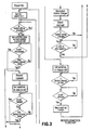
- isolation relays A1 and B1 are closed by command of the PLC, which then closes the relays which connect the variable discharge load with the battery.
- the discharge circuit which is thus created enables module or cell 1 to be discharged across the variable discharge load.
- Module current is measured by a reader within the circuit and fed back to the PLC.
- the PLC then causes the relays connecting the variable discharge load to the battery to open, and then closes the relays which connect the battery charger with the battery, thereby defining a charging circuit which recharges module 1 up to a threshold level which is consistent with the useful capacity of the other modules within the string.
- the procedure is then sequentially repeated for the remaining modules 2, 3,....n within the string.
- the programmable logic controller comprises, or is connected to at least one module voltage reader; at least one battery pack current reader and module current reader; a switch controller to control the isolation relays; a controller for said variable discharge load means and said single module battery charger (charger/discharger controller).
- variable discharge load and battery charger output are adjusted according to the ambient battery and module temperature present to prevent battery damage.
- the computer calculates the a-h (ampere-hour) capacity of each battery cell by integrating the discharge current over the time taken to reach the cut-off voltage threshold, or the energy capacity by the above integration of current times voltage over discharge time in hours.
- a-h ampere-hour
- the means used to discharge the module may be a use specific variable discharge profile, constant current, constant resistance, or constant power.
- the method chosen will depend on the battery technology and the normal usage. To implement these methods, a variable resistor or the like is typically used.
- the battery charger used to recharge the module under scrutiny may operate with a variety of algorithms including constant voltage/current, constant power and fast charge methods, including pulse charging.
- relays A, B and C shown in Figures 2 and 3 may be replaced with solid state switches.
- solid state devices have the following characteristics which affect their suitability as replacements for relays:
- the invention works as an integral part of the battery and is designed to continue to operate in the event of an AC power failure, and is able to provide a full load current to substitute for a partially discharged module. This ensures that the useful capacity of the battery pack is available and that the module is protected from reverse-voltage damage.
- an external module So that no capacity is lost in the unlikely event of the module battery charger failing when the isolated battery is discharged, extra capacity is provided in the form of an external module.
- This module will normally be float charged by the invention.
- the external module or battery When the battery charger fails during a discharge cycle, the external module or battery will be used to power the battery charger.
- the device of the present invention may further comprise an alarm circuit which conveys an audible or visible warning signal that the capacity of the battery pack has fallen below useful level, which is particularly important where the battery pack is being used as a back-up power source.
- an alarm circuit which conveys an audible or visible warning signal that the capacity of the battery pack has fallen below useful level, which is particularly important where the battery pack is being used as a back-up power source.
- This provides the: option of replacing individual batteries from the battery instead of the whole pack, thereby providing a substantial increase in battery pack life and a resulting decrease in battery cost to the user.
- a plurality of the devices of the present invention may be networked to permit the gathering of data required for the effective management of systems with multiple battery installations. The data collected from the network is collated in one central data center. This eases the problem of handling a large amount of data, enables the analysis of standby power in large, complex systems, which facilitates the making of rapid, well-informed decisions.
- the embodiment shown in Figure 4 is a network of a plurality battery health management devices (shown in Figures 1 or 2 herein) installed in conjunction with the battery back up power sources for multiple, remote installations at sites on a telecommunications or other similar network or system.
- the remote battery health management devices are linked by multiple communications or sub-networks to one or more instations.
- the instation is equipped with suitable software to enable the instation to log data from the remote installations, generates alarms, produce statistics, group data in tables for comparison, plot trends, extrapolate data generate reports and assist in record keeping.
- the network shown in Figure 4 is application specific and focuses on assisting in the routine health management (including monitoring or power outages) of a remote battery, such as remote cellular site. Because of the emphasis on routine maintenance, the instation presents information such as battery back time remaining, alarms, maintenance records, site down time and power outages records.
- the system is equipped with extensive database facilities that are used for trending or to provide historical evidence of battery system status.
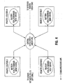
- FIG. 5 A more sophisticated type of network is depicted in Figure 5 which comprises a plurality of individual battery health management installations and/or one or more application specific networks. All of the data collected at the individual installations or sites on this network are collated at a master control center which is equipped to manage battery maintenance of individual sites or systems by providing routine monitoring, and/or diagnostic assistance.
- the master control center may be staffed with personnel who are well acquainted with battery systems and maintenance and who are able to analyse problems as reflected by the incoming data, and who can further provide and implement constructive and remedial advice.
- a battery health management device shown as sites in the networks depicted in Figures 4 and 5 may use an inserted connection circuit, shown in Figure 6, in place of the bridged connection circuit shown in Figures 1 and 2.
- An inserted connection circuit isolates one of the multiple modules in the battery pack (typically nine or eleven modules) by taking the cell out of the trickle/float charge circuit and then performing a discharge of the battery module which drains the energy of the module into variable discharge means such as a fixed resistance heater or similar device at the normal rated load capacity for that module.
- the PLC then records which module is being discharged, and how long it takes to discharge to a pre-programmed cut-off voltage. This information is then used to calculate how much energy the module was able to deliver under actual loaded conditions, thereby providing a real measure of its useful capacity.
- the information on module capacity is provided by way of a liquid crystal display, or similar means, and is given in watt-hours, ampere-hours; % of "as new" or the time to failure under load in minutes, whichever is required by the end user.
- a liquid crystal display or similar means
- % of "as new” or the time to failure under load in minutes whichever is required by the end user.
- batteries B1, B2 and B3 operate a charge/load circuit V.
- Isolation relays or contacts A and B connect an individual module to a monitor circuit, while contact C closes the gap in the battery created by the removal of the module.
- relay contact C When relay contact C is closed, the open circuit formed by the removal of the battery module is closed, thereby allowing current to flow through the charge/ load circuit.
- isolation relays A, B When isolation relays A, B are closed, an individual battery module can be isolated and connected to the monitor circuit. The monitor circuit discharges the isolated battery module and charges it as required using feedback provided by the current sensor and the preset voltage limits.
- the battery voltage would normally be (Vc * N-1) where Vc is the nominal module voltage and N is the number of modules in the battery.
- Vc the nominal module voltage
- N the number of modules in the battery.
- the module to be measured is accordingly isolated from the other modules comprising the battery pack by the selective engagement of isolation relays.
- the module is then discharged, its capacity is measured by the PLC as a function of the discharge load, and it is then recharged.
- the isolated module is temporarily unable to contribute to the output of the battery.
- the procedure is sequentially repeated, at selectable times, for the remaining modules which comprise the battery pack.
- an identical module to the battery modules in the battery pack can be added to the battery pack; for example, making a 9 module battery pack into a 10 module battery pack.
- the module battery charger will be powered from the battery pack.
- the invention can assess the state of health of the reduced capacity module and electrically isolate it from the rest of the battery pack, until such time as the rest of the pack has a poorer performing module than the isolated, reduced capacity module.
Landscapes
- Engineering & Computer Science (AREA)
- Power Engineering (AREA)
- Physics & Mathematics (AREA)
- General Physics & Mathematics (AREA)
- Charge And Discharge Circuits For Batteries Or The Like (AREA)
- Secondary Cells (AREA)
- Stand-By Power Supply Arrangements (AREA)
- Remote Monitoring And Control Of Power-Distribution Networks (AREA)
Claims (16)
- System- zur direkten Bestimmung der nutzbaren Kapazität mindestens eines Batteriemoduls in einem Batteriesatz, und/oder- zum Durchlaufen von Batteriemodulen in einem Batteriesatz, während der Batteriesatz in Betrieb bleibt, und/oder- zur Batteriezustandspflege von insbesondere fern angeordneten Reservebatteriesätzen,
wobei das System umfasst:- eine Kontrollschaltung, die mit einem Steuergerät mit programmierbarer Logik funktionsfähig verbunden ist und mit einem oder mehreren Batteriemodulen im Batteriesatz, wobei die Kontrollschaltung umfasst-- Batteriemodullademittel,-- Entladungsmittel, insbesondere Entladungsmittel zum Entladen des Batteriemoduls, und-- mindestens ein Strommessmittel zur Messung eines Entladungsstromes und/oder eines Ladestromes des mindestens einen Batteriemoduls,- das Steuergerät mit programmierbarer Logik zur Berechnung von Daten mit Bezug auf die nützliche Kapazität des Batteriemoduls aus dem Strom des mindestens einen Batteriemoduls, und- mehrere Relais, die vom Steuergerät mit programmierbarer Logik gesteuert werden und zwischen die Kontrollschaltung und den Batteriesatz geschaltet sind und insbesondere zwischen dem Batteriemodullademittel, dem Entladungsmittel und den Batteriemodulen angeschlossen sind,
wobei das Steuergerät mit programmierbarer Logik dafür entworfen ist,- die Batteriemodullademittel zu kontrollieren und die Entladungsmittel, und- wahlweise und insbesondere aufeinanderfolgend die mehreren Relais zu öffnen und zu schließen, die mit den Batteriemodullademitteln und den Entladungsmitteln verbinden,-- um mindestens ein Batteriemodul im Batteriesatz an das Batteriemodullademittel anzuschließen oder an das Entladungsmittel und/oder-- alternativ eine Entladungsschaltung festzulegen, die ermöglicht, eins der Module durch die Entladungsmittel zu entladen und durch die genannten Batteriemodullademittel wieder aufzuladen. - System gemäß Anspruch 1, in dem- das genannte Steuergerät mit programmierbarer Logik durch eine Kommunikationsverbindung mit einem Datenzentrum verbunden ist, das Daten zusammenstellt und verarbeitet, die durch das genannte Steuergerät mit programmierbarer Logik übertragen werden, und- Daten mit Bezug auf die nutzbare Kapazität des Batteriemoduls durch das genannte Steuergerät mit programmierbarer Logik berechnet und an das genannte Datenzentrum übertragen werden.
- System gemäß Anspruch 1 oder 2, außerdem Mittel zur Speicherung der genannten Daten, die vom genannten Steuergerät mit programmierbarer Logik berechnet werden, umfassend.
- System gemäß mindestens einem der Ansprüche 1 bis 3, in dem die genannten Relais aus der Gruppe ausgewählt sind, die aus Mehrfachrelais, Schützen oder Festkörperschaltvorrichtungen besteht.
- System gemäß mindestens einem der Ansprüche 1 bis 4, in dem das Entladungsmittel zur Entladung des mindestens einen Batteriemoduls außerdem Mittel zur Entladung des mindestens einen Batteriemoduls unter eine festgelegte Ladung umfasst.
- System gemäß mindestens einem der Ansprüche 1 bis 5, in dem das Entladungsmittel zur Entladung des mindestens einen Batteriemoduls außerdem Mittel zur variablen Entladung des mindestens einen Batteriemoduls umfasst.
- System gemäß mindestens einem der Ansprüche 1 bis 6, in dem das Steuergerät mit programmierbarer Logik umfasst:- eine Schalterbetätigungseinrichtung zur Steuerung der mehreren Relais,- eine Regeleinrichtung für das Entladungsmittel, und- eine Regeleinrichtung für das Batteriemodullademittel.
- System gemäß mindestens einem der Ansprüche 1 bis 7, in dem das Datenzentrum ein Hauptsteuerungszentrum ist, das mehrere Dienstleistungen liefert, einschließlich Routinekontroll- und Diagnosehilfe.
- System gemäß mindestens einem der Ansprüche 1 bis 8, gekennzeichnet durch Erhöhung der nutzbaren Kapazität und/oder Verringerung der Kapazitätsverlustrate des Batteriesatzes im Betrieb durch Anwendung eines optimalen Ladeverfahrens auf das Batteriemodul, das im genannten Batteriesatz enthalten ist, während der genannte Batteriesatz im Betrieb bleibt, wobei die mehreren verschiedenen Ladeverfahren aus der Gruppe ausgewählt werden, die umfasst:a) mit konstanter Spannung,b) mit konstantem Strom,c) mit konstanter Leistungd) Schnellladung,e) Pulsladung.
- Verfahren zur Abschätzung der nutzbaren Kapazität mehrerer Batteriemodule, die einen Batteriesatz bilden, nacheinander, wobei das Verfahren die folgenden Schritte umfasst:- Bereitstellung eines Steuergerätes mit einer Betätigungseinrichtung zur Steuerung des Öffnens und Schließens von Relais,- Auswahl eines der genannten Module für die Abschätzung,- Verbindung des genannten ausgewählten Moduls mit einem Mittel zur variablen Entladung durch Schließen des genannten Relais, das das genannte Modul mit dem genannten Mittel zur variablen Entladung verbindet,- Messung von Stromparametern, die die nutzbare Kapazität des genannten Moduls bestimmen, während das genannte Modul geladen ist,- Feststellen, ob die genannte nutzbare Kapazität einem festgelegten Schwellenwert der nutzbaren Kapazität entspricht,- Trennen des genannten ausgewählten Moduls vom genannten Mittel zur variablen Entladung durch Öffnen des genannten Relais und
entweder Wiederaufladen des genannten ausgewählten Moduls durch Verbindung des genannten ausgewählten Moduls mit einem Batteriemodullademittel, wenn die genannte nutzbare Kapazität dem genannten festgelegten Schwellenwert entspricht
oder Erzeugung eines Signals, wenn die genannte nutzbare Kapazität dem genannten Schwellenwert nicht entspricht,
wobei- die obigen Schritte vom genannten Steuergerät mit programmierbarer Logik koordiniert werden, das funktionsfähig in Kombination umfasst:-- mindestens einen Spannungsableser,-- mindestens einen Batteriestromableser und-- mindestens einen Modulstromableser. - Verfahren gemäß Anspruch 10, in dem das Entladungsmittel das ausgewählte Modul bei einer festgelegten Ladung entlädt.
- Verfahren gemäß Anspruch 10 oder 11, in dem das Entladungsmittel das ausgewählte Modul bei variablen Ladungen entlädt.
- Verfahren gemäß mindestens einem der Ansprüche 10 bis 12, außerdem die Speicherung von Kapazitätsdaten mit Bezug auf die nutzbare Kapazität des ausgewählten Moduls umfassend.
- Verfahren gemäß mindestens einem der Ansprüche 10 bis 13, außerdem die Bestimmung einer Kapazität anderer Module im Batteriesatz aus gespeicherten Kapazitätswerten anderer Module im Batteriesatz umfassend und das Wiederaufladen des ausgewählten Moduls durch Verbinden des ausgewählten Moduls mit dem Batteriemodullademittel, wobei das ausgewählte Modul auf einen Wiederaufladungswert aufgeladen wird, der mit der Kapazität anderer Module im Batteriesatz konsistent ist.
- Verfahren gemäß mindestens einem der Ansprüche 10 bis 14, in dem das Entladungsmittel das mindestens eine Batteriemodul bei einer bestimmten Ladung entlädt.
- Verfahren gemäß mindestens einem der Ansprüche 10 bis 15, in dem das Entladungsmittel das mindestens eine Batteriemodul bei variablen Ladungen entlädt.
Applications Claiming Priority (5)
| Application Number | Priority Date | Filing Date | Title |
|---|---|---|---|
| US08/887,844 US6239579B1 (en) | 1996-07-05 | 1997-07-03 | Device for managing battery packs by selectively monitoring and assessing the operative capacity of the battery modules in the pack |
| US887844 | 1997-07-03 | ||
| CA2209817 | 1997-07-04 | ||
| CA002209817A CA2209817C (en) | 1996-07-05 | 1997-07-04 | Device for managing battery packs by monitoring and assessing the operating capacity of the battery modules in the pack |
| PCT/CA1998/000650 WO1999001918A2 (en) | 1997-07-03 | 1998-07-03 | Device and system for management of battery back up power source |
Publications (2)
| Publication Number | Publication Date |
|---|---|
| EP0992100A2 EP0992100A2 (de) | 2000-04-12 |
| EP0992100B1 true EP0992100B1 (de) | 2007-04-25 |
Family
ID=25679471
Family Applications (1)
| Application Number | Title | Priority Date | Filing Date |
|---|---|---|---|
| EP98931856A Expired - Lifetime EP0992100B1 (de) | 1997-07-03 | 1998-07-03 | Einrichtung und methode für die verwaltung einer batterienotstromversorgungseinrichtung |
Country Status (5)
| Country | Link |
|---|---|
| EP (1) | EP0992100B1 (de) |
| AT (1) | ATE360909T1 (de) |
| AU (1) | AU8202298A (de) |
| DE (1) | DE69837661T2 (de) |
| WO (1) | WO1999001918A2 (de) |
Cited By (8)
| Publication number | Priority date | Publication date | Assignee | Title |
|---|---|---|---|---|
| US7456736B2 (en) | 2003-04-14 | 2008-11-25 | American Power Conversion Corporation | Extensible sensor monitoring, alert processing and notification system and method |
| US7529838B2 (en) | 2001-01-26 | 2009-05-05 | American Power Conversion Corporation | Method and system for a set of network appliances which can be connected to provide enhanced collaboration, scalability, and reliability |
| US7711814B1 (en) | 2004-12-13 | 2010-05-04 | American Power Conversion Corporation | Method and system for remote monitoring of a power supply device with user registration capability |
| US7958170B2 (en) | 2002-05-03 | 2011-06-07 | American Power Conversion Corporation | Method and apparatus for collecting and displaying data associated with network devices |
| US8005944B2 (en) | 1999-10-27 | 2011-08-23 | American Power Conversion Corporation | Method and system for monitoring computer networks and equipment |
| US8145748B2 (en) | 2004-12-13 | 2012-03-27 | American Power Conversion Corporation | Remote monitoring system |
| US11215679B2 (en) | 2016-09-27 | 2022-01-04 | Huawei Technologies Co., Ltd. | Method and apparatus for detecting micro short circuit of battery |
| US12420667B2 (en) | 2019-04-02 | 2025-09-23 | Shenzhen Yinwang Intelligent Technologies Co., Ltd. | Battery pack internal short circuit detection method and related apparatus, and electric vehicle |
Families Citing this family (36)
| Publication number | Priority date | Publication date | Assignee | Title |
|---|---|---|---|---|
| GB9820271D0 (en) * | 1998-09-17 | 1998-11-11 | Simoco Int Ltd | A method of and apparatus for monitoring the condition of batteries used by a mobile radio telecommunications fleet |
| JP3495636B2 (ja) * | 1999-03-25 | 2004-02-09 | 株式会社マキタ | 充電装置 |
| US7330886B2 (en) | 1999-10-27 | 2008-02-12 | American Power Conversion Corporation | Network appliance management |
| US7392309B2 (en) | 1999-10-27 | 2008-06-24 | American Power Conversion Corporation | Network appliance management |
| FR2800525B1 (fr) * | 1999-11-02 | 2001-12-21 | Accunord | Dispositif de controle de l'etat des accumulateurs d'une batterie |
| GB2359426A (en) * | 2000-02-18 | 2001-08-22 | Delta Impact Ltd | Battery back-up with deep discharge cycling |
| US8271626B2 (en) | 2001-01-26 | 2012-09-18 | American Power Conversion Corporation | Methods for displaying physical network topology and environmental status by location, organization, or responsible party |
| GB2392026B (en) | 2001-05-14 | 2005-09-21 | Invensys Energy Systems | Stress management of battery recharge, and method of state of charge estimation |
| HK1045076A2 (en) * | 2001-09-03 | 2002-11-01 | 金柏电子国际有限公司 | An intelligent serial battery charger and charging block |
| AU2003267882A1 (en) | 2002-09-26 | 2004-04-19 | Eaton Power Quality Limited | Modular battery management apparatus with cell sensing and energy redistribution capabilities |
| EP1616237B1 (de) | 2003-04-14 | 2017-10-25 | Schneider Electric IT Corporation | Umgebungsüberwachungseinrichtung |
| EP1616236B1 (de) | 2003-04-14 | 2016-11-23 | Schneider Electric IT Corporation | Verfahren und system zum journaling und zugreifen auf sensor- und konfigurationsdaten |
| US8566292B2 (en) | 2003-04-14 | 2013-10-22 | Schneider Electric It Corporation | Method and system for journaling and accessing sensor and configuration data |
| US7196494B2 (en) | 2003-10-17 | 2007-03-27 | Xantrex International | Method and apparatus for charging batteries in a system of batteries |
| US7627651B2 (en) | 2003-10-27 | 2009-12-01 | American Power Conversion Corporation | System and method for network device communication |
| US20050127874A1 (en) * | 2003-12-12 | 2005-06-16 | Myoungho Lim | Method and apparatus for multiple battery cell management |
| EP1641099A1 (de) * | 2004-09-24 | 2006-03-29 | Conception et Développement Michelin S.A. | Abnehmbarer Ladezustandsregler für den Spannungsausgleich einer Serienschaltung von Doppelschichtkondensatoren |
| KR100740107B1 (ko) | 2005-09-08 | 2007-07-16 | 삼성에스디아이 주식회사 | 제어신호 생성회로 및 이를 이용한 배터리 관리 시스템 |
| US7723957B2 (en) | 2005-11-30 | 2010-05-25 | Lg Chem, Ltd. | System, method, and article of manufacture for determining an estimated battery parameter vector |
| DK2147585T3 (en) | 2007-05-15 | 2017-01-16 | Schneider Electric It Corp | PROCEDURE AND SYSTEM FOR HANDLING EQUIPMENT AND COOLING |
| TWM332909U (en) * | 2007-11-30 | 2008-05-21 | Lifebatt Production Inc | Far-end monitoring system for a battery module of an electromotive vehicle |
| US8598845B2 (en) * | 2009-04-20 | 2013-12-03 | Valence Technology, Inc. | Battery chargers, electrical systems, and rechargeable battery charging methods |
| GB0915299D0 (en) * | 2009-09-03 | 2009-10-07 | Scott Nigel D | Watchman hybrid |
| US8547064B2 (en) * | 2010-01-14 | 2013-10-01 | Texas Instruments Incorporated | Battery cell tab monitor |
| DE102010021176A1 (de) * | 2010-05-21 | 2011-11-24 | Metabowerke Gmbh | Anordnung zur Einzelzellenmessung in einem Akkupack und einem Akkupack mit einer solchen Anordnung |
| DE102011008934A1 (de) * | 2011-01-19 | 2012-07-19 | Bmz Batterien-Montage-Zentrum Gmbh | Integriertes Batteriemanagement System |
| US8990536B2 (en) | 2011-06-01 | 2015-03-24 | Schneider Electric It Corporation | Systems and methods for journaling and executing device control instructions |
| US9952103B2 (en) | 2011-12-22 | 2018-04-24 | Schneider Electric It Corporation | Analysis of effect of transient events on temperature in a data center |
| CN103234579A (zh) * | 2013-03-29 | 2013-08-07 | 国家电网公司 | 一种储能电池参数在线检测的数据处理方法 |
| US9658290B2 (en) * | 2013-11-20 | 2017-05-23 | Life Safety Distribution Ag | System and method of battery life estimation |
| DE102014201363A1 (de) | 2014-01-27 | 2015-07-30 | Robert Bosch Gmbh | Verfahren und Schaltungsanordnung zur Bestimmung des Coulomb-Wirkungsgrades von Batteriemodulen |
| DE102014201365A1 (de) | 2014-01-27 | 2015-07-30 | Robert Bosch Gmbh | Verfahren und Schaltungsanordnung zur Bestimmung des Coulomb-Wirkungsgrades von Batteriemodulen |
| WO2015200912A1 (en) * | 2014-06-27 | 2015-12-30 | Icc-Nexergy, Inc. | Required available capacity indication for battery backup unit |
| SE540739C2 (en) * | 2016-06-02 | 2018-10-30 | Megger Sweden Ab | Device and method for loading a voltage source |
| CN117239881B (zh) * | 2023-11-10 | 2024-03-15 | 深圳市立泰能源科技有限公司 | 一种船用电池组冗余过充保护管理系统及方法 |
| CN119619682A (zh) * | 2024-12-20 | 2025-03-14 | 福建汉特云智能科技有限公司 | 一种智能机器人电源管理模块充电测试系统及方法 |
Family Cites Families (6)
| Publication number | Priority date | Publication date | Assignee | Title |
|---|---|---|---|---|
| US4484140A (en) * | 1982-04-23 | 1984-11-20 | The United States Of America As Represented By The Secretary Of The Navy | Battery scanning system |
| US4707795A (en) * | 1983-03-14 | 1987-11-17 | Alber Engineering, Inc. | Battery testing and monitoring system |
| DE3821808C2 (de) * | 1988-06-28 | 1994-06-16 | Helmut Haendel & Partner Mesda | Verfahren und Vorrichtung zum automatischen Testen von Akkumulatoren einer unterbrechungsfreien Stromversorgungsanlage |
| US5153496A (en) * | 1990-09-27 | 1992-10-06 | Baxtrer International Inc. | Cell monitor and control unit for multicell battery |
| FR2702885B1 (fr) * | 1993-03-15 | 1995-04-21 | Alcatel Converters | Système de contrôle de vieillissement d'une batterie et procédé mis en Óoeuvre dans un tel système. |
| US5710503A (en) * | 1996-02-01 | 1998-01-20 | Aims Systems, Inc. | On-line battery monitoring system with defective cell detection capability |
-
1998
- 1998-07-03 AU AU82022/98A patent/AU8202298A/en not_active Abandoned
- 1998-07-03 DE DE69837661T patent/DE69837661T2/de not_active Expired - Lifetime
- 1998-07-03 AT AT98931856T patent/ATE360909T1/de not_active IP Right Cessation
- 1998-07-03 WO PCT/CA1998/000650 patent/WO1999001918A2/en not_active Ceased
- 1998-07-03 EP EP98931856A patent/EP0992100B1/de not_active Expired - Lifetime
Non-Patent Citations (1)
| Title |
|---|
| None * |
Cited By (10)
| Publication number | Priority date | Publication date | Assignee | Title |
|---|---|---|---|---|
| US8005944B2 (en) | 1999-10-27 | 2011-08-23 | American Power Conversion Corporation | Method and system for monitoring computer networks and equipment |
| US7529838B2 (en) | 2001-01-26 | 2009-05-05 | American Power Conversion Corporation | Method and system for a set of network appliances which can be connected to provide enhanced collaboration, scalability, and reliability |
| US7958170B2 (en) | 2002-05-03 | 2011-06-07 | American Power Conversion Corporation | Method and apparatus for collecting and displaying data associated with network devices |
| US8019798B2 (en) | 2002-05-03 | 2011-09-13 | American Power Conversion Corporation | Method and apparatus for collecting and displaying network device information |
| US8719319B2 (en) | 2002-05-03 | 2014-05-06 | Schneider Electric It Corporation | Method and apparatus for collecting and displaying network device information |
| US7456736B2 (en) | 2003-04-14 | 2008-11-25 | American Power Conversion Corporation | Extensible sensor monitoring, alert processing and notification system and method |
| US7711814B1 (en) | 2004-12-13 | 2010-05-04 | American Power Conversion Corporation | Method and system for remote monitoring of a power supply device with user registration capability |
| US8145748B2 (en) | 2004-12-13 | 2012-03-27 | American Power Conversion Corporation | Remote monitoring system |
| US11215679B2 (en) | 2016-09-27 | 2022-01-04 | Huawei Technologies Co., Ltd. | Method and apparatus for detecting micro short circuit of battery |
| US12420667B2 (en) | 2019-04-02 | 2025-09-23 | Shenzhen Yinwang Intelligent Technologies Co., Ltd. | Battery pack internal short circuit detection method and related apparatus, and electric vehicle |
Also Published As
| Publication number | Publication date |
|---|---|
| WO1999001918A3 (en) | 1999-04-22 |
| DE69837661D1 (de) | 2007-06-06 |
| ATE360909T1 (de) | 2007-05-15 |
| EP0992100A2 (de) | 2000-04-12 |
| DE69837661T2 (de) | 2007-12-27 |
| AU8202298A (en) | 1999-01-25 |
| WO1999001918A2 (en) | 1999-01-14 |
Similar Documents
| Publication | Publication Date | Title |
|---|---|---|
| EP0992100B1 (de) | Einrichtung und methode für die verwaltung einer batterienotstromversorgungseinrichtung | |
| US6329792B1 (en) | Device and system for management of battery back up power source | |
| CA2209817C (en) | Device for managing battery packs by monitoring and assessing the operating capacity of the battery modules in the pack | |
| US6504344B1 (en) | Monitoring battery packs | |
| EP1396065B1 (de) | Notstromversorgungssystem | |
| US6133709A (en) | Signalling system | |
| US7728552B2 (en) | Battery management system and method | |
| WO1999010854A1 (en) | Battery capacity monitoring system | |
| EP3295192A1 (de) | System und verfahren zur überwachung eines gleichstromsystem | |
| US7567060B1 (en) | System and method for advanced power management | |
| CN110116622A (zh) | 轨道车辆用蓄电池系统 | |
| US8525485B2 (en) | System and method for applying pulsation energy to online battery backup systems | |
| CN111999663A (zh) | 电池连接线断线检测装置 | |
| JP5409163B2 (ja) | リチウムイオン組電池管理装置、管理方法およびリチウムイオン組電池システム | |
| CN111969676A (zh) | 基于主动均衡的电池连接线断线检测方法 | |
| JP2011029010A (ja) | リチウムイオン二次電池システムおよび管理装置への電力供給方法 | |
| KR20220042963A (ko) | 릴레이 고장 검출 방법, 배터리 관리 시스템 및 이를 포함하는 배터리 팩 | |
| CN110165310A (zh) | 一种电池组智能管控系统 | |
| EP2837082B1 (de) | Verfahren und system für distanzmessung der verfügbaren kapazität von batterien in einem telekommunikationssystem | |
| JP4392176B2 (ja) | 組電池容量試験装置および組電池容量試験方法 | |
| CA2317045C (en) | Device and system for management of battery back up power source | |
| CN119209871A (zh) | 变电站直流蓄电池组落后电池不停电置换装置 | |
| US20050007071A1 (en) | Circuit arrangement for an autonomous power supply system, and a method for its operation | |
| CN111697659A (zh) | 一种电池管理电路 | |
| CN117517947B (zh) | 一种高压箱继电器触点粘连监测方法及装置 |
Legal Events
| Date | Code | Title | Description |
|---|---|---|---|
| PUAI | Public reference made under article 153(3) epc to a published international application that has entered the european phase |
Free format text: ORIGINAL CODE: 0009012 |
|
| 17P | Request for examination filed |
Effective date: 20000126 |
|
| AK | Designated contracting states |
Kind code of ref document: A2 Designated state(s): AT BE CH CY DE DK ES FI FR GB GR IE IT LI LU MC NL PT SE |
|
| 17Q | First examination report despatched |
Effective date: 20010723 |
|
| RAP1 | Party data changed (applicant data changed or rights of an application transferred) |
Owner name: ESTCO BATTERY MANAGEMENT, INC. |
|
| GRAP | Despatch of communication of intention to grant a patent |
Free format text: ORIGINAL CODE: EPIDOSNIGR1 |
|
| RTI1 | Title (correction) |
Free format text: SYSTEM AND METHOD FOR MANAGEMENT OF BATTERY BACK UP POWER SOURCE |
|
| GRAS | Grant fee paid |
Free format text: ORIGINAL CODE: EPIDOSNIGR3 |
|
| RAP1 | Party data changed (applicant data changed or rights of an application transferred) |
Owner name: R.V. HOLDINGS CORP. IN TRUST |
|
| 17Q | First examination report despatched |
Effective date: 20010723 |
|
| GRAA | (expected) grant |
Free format text: ORIGINAL CODE: 0009210 |
|
| AK | Designated contracting states |
Kind code of ref document: B1 Designated state(s): AT BE CH CY DE DK ES FI FR GB GR IE IT LI LU MC NL PT SE |
|
| PG25 | Lapsed in a contracting state [announced via postgrant information from national office to epo] |
Ref country code: LI Free format text: LAPSE BECAUSE OF FAILURE TO SUBMIT A TRANSLATION OF THE DESCRIPTION OR TO PAY THE FEE WITHIN THE PRESCRIBED TIME-LIMIT Effective date: 20070425 Ref country code: FI Free format text: LAPSE BECAUSE OF FAILURE TO SUBMIT A TRANSLATION OF THE DESCRIPTION OR TO PAY THE FEE WITHIN THE PRESCRIBED TIME-LIMIT Effective date: 20070425 Ref country code: CH Free format text: LAPSE BECAUSE OF FAILURE TO SUBMIT A TRANSLATION OF THE DESCRIPTION OR TO PAY THE FEE WITHIN THE PRESCRIBED TIME-LIMIT Effective date: 20070425 |
|
| REG | Reference to a national code |
Ref country code: GB Ref legal event code: FG4D |
|
| REG | Reference to a national code |
Ref country code: IE Ref legal event code: FG4D |
|
| REG | Reference to a national code |
Ref country code: CH Ref legal event code: EP |
|
| REF | Corresponds to: |
Ref document number: 69837661 Country of ref document: DE Date of ref document: 20070606 Kind code of ref document: P |
|
| PG25 | Lapsed in a contracting state [announced via postgrant information from national office to epo] |
Ref country code: SE Free format text: LAPSE BECAUSE OF FAILURE TO SUBMIT A TRANSLATION OF THE DESCRIPTION OR TO PAY THE FEE WITHIN THE PRESCRIBED TIME-LIMIT Effective date: 20070725 |
|
| PG25 | Lapsed in a contracting state [announced via postgrant information from national office to epo] |
Ref country code: ES Free format text: LAPSE BECAUSE OF FAILURE TO SUBMIT A TRANSLATION OF THE DESCRIPTION OR TO PAY THE FEE WITHIN THE PRESCRIBED TIME-LIMIT Effective date: 20070805 |
|
| PG25 | Lapsed in a contracting state [announced via postgrant information from national office to epo] |
Ref country code: PT Free format text: LAPSE BECAUSE OF FAILURE TO SUBMIT A TRANSLATION OF THE DESCRIPTION OR TO PAY THE FEE WITHIN THE PRESCRIBED TIME-LIMIT Effective date: 20070925 |
|
| ET | Fr: translation filed | ||
| REG | Reference to a national code |
Ref country code: CH Ref legal event code: PL |
|
| NLV1 | Nl: lapsed or annulled due to failure to fulfill the requirements of art. 29p and 29m of the patents act | ||
| PG25 | Lapsed in a contracting state [announced via postgrant information from national office to epo] |
Ref country code: AT Free format text: LAPSE BECAUSE OF FAILURE TO SUBMIT A TRANSLATION OF THE DESCRIPTION OR TO PAY THE FEE WITHIN THE PRESCRIBED TIME-LIMIT Effective date: 20070425 |
|
| PG25 | Lapsed in a contracting state [announced via postgrant information from national office to epo] |
Ref country code: BE Free format text: LAPSE BECAUSE OF FAILURE TO SUBMIT A TRANSLATION OF THE DESCRIPTION OR TO PAY THE FEE WITHIN THE PRESCRIBED TIME-LIMIT Effective date: 20070425 |
|
| PG25 | Lapsed in a contracting state [announced via postgrant information from national office to epo] |
Ref country code: NL Free format text: LAPSE BECAUSE OF FAILURE TO SUBMIT A TRANSLATION OF THE DESCRIPTION OR TO PAY THE FEE WITHIN THE PRESCRIBED TIME-LIMIT Effective date: 20070425 Ref country code: DK Free format text: LAPSE BECAUSE OF FAILURE TO SUBMIT A TRANSLATION OF THE DESCRIPTION OR TO PAY THE FEE WITHIN THE PRESCRIBED TIME-LIMIT Effective date: 20070425 |
|
| PLBE | No opposition filed within time limit |
Free format text: ORIGINAL CODE: 0009261 |
|
| STAA | Information on the status of an ep patent application or granted ep patent |
Free format text: STATUS: NO OPPOSITION FILED WITHIN TIME LIMIT |
|
| 26N | No opposition filed |
Effective date: 20080128 |
|
| PG25 | Lapsed in a contracting state [announced via postgrant information from national office to epo] |
Ref country code: MC Free format text: LAPSE BECAUSE OF NON-PAYMENT OF DUE FEES Effective date: 20070731 Ref country code: IT Free format text: LAPSE BECAUSE OF FAILURE TO SUBMIT A TRANSLATION OF THE DESCRIPTION OR TO PAY THE FEE WITHIN THE PRESCRIBED TIME-LIMIT Effective date: 20070425 Ref country code: GR Free format text: LAPSE BECAUSE OF FAILURE TO SUBMIT A TRANSLATION OF THE DESCRIPTION OR TO PAY THE FEE WITHIN THE PRESCRIBED TIME-LIMIT Effective date: 20070726 |
|
| PG25 | Lapsed in a contracting state [announced via postgrant information from national office to epo] |
Ref country code: IE Free format text: LAPSE BECAUSE OF NON-PAYMENT OF DUE FEES Effective date: 20070703 |
|
| PG25 | Lapsed in a contracting state [announced via postgrant information from national office to epo] |
Ref country code: CY Free format text: LAPSE BECAUSE OF FAILURE TO SUBMIT A TRANSLATION OF THE DESCRIPTION OR TO PAY THE FEE WITHIN THE PRESCRIBED TIME-LIMIT Effective date: 20070425 |
|
| PG25 | Lapsed in a contracting state [announced via postgrant information from national office to epo] |
Ref country code: LU Free format text: LAPSE BECAUSE OF NON-PAYMENT OF DUE FEES Effective date: 20070703 |
|
| PGFP | Annual fee paid to national office [announced via postgrant information from national office to epo] |
Ref country code: GB Payment date: 20140702 Year of fee payment: 17 Ref country code: FR Payment date: 20140630 Year of fee payment: 17 |
|
| GBPC | Gb: european patent ceased through non-payment of renewal fee |
Effective date: 20150703 |
|
| PG25 | Lapsed in a contracting state [announced via postgrant information from national office to epo] |
Ref country code: GB Free format text: LAPSE BECAUSE OF NON-PAYMENT OF DUE FEES Effective date: 20150703 |
|
| REG | Reference to a national code |
Ref country code: FR Ref legal event code: ST Effective date: 20160331 |
|
| PG25 | Lapsed in a contracting state [announced via postgrant information from national office to epo] |
Ref country code: FR Free format text: LAPSE BECAUSE OF NON-PAYMENT OF DUE FEES Effective date: 20150731 |
|
| PGFP | Annual fee paid to national office [announced via postgrant information from national office to epo] |
Ref country code: DE Payment date: 20170613 Year of fee payment: 20 |
|
| REG | Reference to a national code |
Ref country code: DE Ref legal event code: R071 Ref document number: 69837661 Country of ref document: DE |