EP0993385B1 - Elektrische getriebeeinheit - Google Patents
Elektrische getriebeeinheit Download PDFInfo
- Publication number
- EP0993385B1 EP0993385B1 EP98941316A EP98941316A EP0993385B1 EP 0993385 B1 EP0993385 B1 EP 0993385B1 EP 98941316 A EP98941316 A EP 98941316A EP 98941316 A EP98941316 A EP 98941316A EP 0993385 B1 EP0993385 B1 EP 0993385B1
- Authority
- EP
- European Patent Office
- Prior art keywords
- transmission unit
- generator
- drive arrangement
- drive
- electric
- Prior art date
- Legal status (The legal status is an assumption and is not a legal conclusion. Google has not performed a legal analysis and makes no representation as to the accuracy of the status listed.)
- Expired - Lifetime
Links
Images


Classifications
-
- B—PERFORMING OPERATIONS; TRANSPORTING
- B60—VEHICLES IN GENERAL
- B60K—ARRANGEMENT OR MOUNTING OF PROPULSION UNITS OR OF TRANSMISSIONS IN VEHICLES; ARRANGEMENT OR MOUNTING OF PLURAL DIVERSE PRIME-MOVERS IN VEHICLES; AUXILIARY DRIVES FOR VEHICLES; INSTRUMENTATION OR DASHBOARDS FOR VEHICLES; ARRANGEMENTS IN CONNECTION WITH COOLING, AIR INTAKE, GAS EXHAUST OR FUEL SUPPLY OF PROPULSION UNITS IN VEHICLES
- B60K6/00—Arrangement or mounting of plural diverse prime-movers for mutual or common propulsion, e.g. hybrid propulsion systems comprising electric motors and internal combustion engines
- B60K6/20—Arrangement or mounting of plural diverse prime-movers for mutual or common propulsion, e.g. hybrid propulsion systems comprising electric motors and internal combustion engines the prime-movers consisting of electric motors and internal combustion engines, e.g. HEVs
- B60K6/42—Arrangement or mounting of plural diverse prime-movers for mutual or common propulsion, e.g. hybrid propulsion systems comprising electric motors and internal combustion engines the prime-movers consisting of electric motors and internal combustion engines, e.g. HEVs characterised by the architecture of the hybrid electric vehicle
- B60K6/46—Series type
-
- B—PERFORMING OPERATIONS; TRANSPORTING
- B60—VEHICLES IN GENERAL
- B60K—ARRANGEMENT OR MOUNTING OF PROPULSION UNITS OR OF TRANSMISSIONS IN VEHICLES; ARRANGEMENT OR MOUNTING OF PLURAL DIVERSE PRIME-MOVERS IN VEHICLES; AUXILIARY DRIVES FOR VEHICLES; INSTRUMENTATION OR DASHBOARDS FOR VEHICLES; ARRANGEMENTS IN CONNECTION WITH COOLING, AIR INTAKE, GAS EXHAUST OR FUEL SUPPLY OF PROPULSION UNITS IN VEHICLES
- B60K1/00—Arrangement or mounting of electrical propulsion units
-
- B—PERFORMING OPERATIONS; TRANSPORTING
- B60—VEHICLES IN GENERAL
- B60K—ARRANGEMENT OR MOUNTING OF PROPULSION UNITS OR OF TRANSMISSIONS IN VEHICLES; ARRANGEMENT OR MOUNTING OF PLURAL DIVERSE PRIME-MOVERS IN VEHICLES; AUXILIARY DRIVES FOR VEHICLES; INSTRUMENTATION OR DASHBOARDS FOR VEHICLES; ARRANGEMENTS IN CONNECTION WITH COOLING, AIR INTAKE, GAS EXHAUST OR FUEL SUPPLY OF PROPULSION UNITS IN VEHICLES
- B60K17/00—Arrangement or mounting of transmissions in vehicles
- B60K17/04—Arrangement or mounting of transmissions in vehicles characterised by arrangement, location or kind of gearing
- B60K17/12—Arrangement or mounting of transmissions in vehicles characterised by arrangement, location or kind of gearing of electric gearing
-
- B—PERFORMING OPERATIONS; TRANSPORTING
- B60—VEHICLES IN GENERAL
- B60L—PROPULSION OF ELECTRICALLY-PROPELLED VEHICLES; SUPPLYING ELECTRIC POWER FOR AUXILIARY EQUIPMENT OF ELECTRICALLY-PROPELLED VEHICLES; ELECTRODYNAMIC BRAKE SYSTEMS FOR VEHICLES IN GENERAL; MAGNETIC SUSPENSION OR LEVITATION FOR VEHICLES; MONITORING OPERATING VARIABLES OF ELECTRICALLY-PROPELLED VEHICLES; ELECTRIC SAFETY DEVICES FOR ELECTRICALLY-PROPELLED VEHICLES
- B60L50/00—Electric propulsion with power supplied within the vehicle
- B60L50/10—Electric propulsion with power supplied within the vehicle using propulsion power supplied by engine-driven generators, e.g. generators driven by combustion engines
-
- B—PERFORMING OPERATIONS; TRANSPORTING
- B60—VEHICLES IN GENERAL
- B60L—PROPULSION OF ELECTRICALLY-PROPELLED VEHICLES; SUPPLYING ELECTRIC POWER FOR AUXILIARY EQUIPMENT OF ELECTRICALLY-PROPELLED VEHICLES; ELECTRODYNAMIC BRAKE SYSTEMS FOR VEHICLES IN GENERAL; MAGNETIC SUSPENSION OR LEVITATION FOR VEHICLES; MONITORING OPERATING VARIABLES OF ELECTRICALLY-PROPELLED VEHICLES; ELECTRIC SAFETY DEVICES FOR ELECTRICALLY-PROPELLED VEHICLES
- B60L50/00—Electric propulsion with power supplied within the vehicle
- B60L50/50—Electric propulsion with power supplied within the vehicle using propulsion power supplied by batteries or fuel cells
- B60L50/60—Electric propulsion with power supplied within the vehicle using propulsion power supplied by batteries or fuel cells using power supplied by batteries
- B60L50/61—Electric propulsion with power supplied within the vehicle using propulsion power supplied by batteries or fuel cells using power supplied by batteries by batteries charged by engine-driven generators, e.g. series hybrid electric vehicles
- B60L50/62—Electric propulsion with power supplied within the vehicle using propulsion power supplied by batteries or fuel cells using power supplied by batteries by batteries charged by engine-driven generators, e.g. series hybrid electric vehicles charged by low-power generators primarily intended to support the batteries, e.g. range extenders
-
- H—ELECTRICITY
- H02—GENERATION; CONVERSION OR DISTRIBUTION OF ELECTRIC POWER
- H02K—DYNAMO-ELECTRIC MACHINES
- H02K51/00—Dynamo-electric gears, i.e. dynamo-electric means for transmitting mechanical power from a driving shaft to a driven shaft and comprising structurally interrelated motor and generator parts
-
- B—PERFORMING OPERATIONS; TRANSPORTING
- B60—VEHICLES IN GENERAL
- B60L—PROPULSION OF ELECTRICALLY-PROPELLED VEHICLES; SUPPLYING ELECTRIC POWER FOR AUXILIARY EQUIPMENT OF ELECTRICALLY-PROPELLED VEHICLES; ELECTRODYNAMIC BRAKE SYSTEMS FOR VEHICLES IN GENERAL; MAGNETIC SUSPENSION OR LEVITATION FOR VEHICLES; MONITORING OPERATING VARIABLES OF ELECTRICALLY-PROPELLED VEHICLES; ELECTRIC SAFETY DEVICES FOR ELECTRICALLY-PROPELLED VEHICLES
- B60L2220/00—Electrical machine types; Structures or applications thereof
- B60L2220/10—Electrical machine types
- B60L2220/14—Synchronous machines
-
- B—PERFORMING OPERATIONS; TRANSPORTING
- B60—VEHICLES IN GENERAL
- B60L—PROPULSION OF ELECTRICALLY-PROPELLED VEHICLES; SUPPLYING ELECTRIC POWER FOR AUXILIARY EQUIPMENT OF ELECTRICALLY-PROPELLED VEHICLES; ELECTRODYNAMIC BRAKE SYSTEMS FOR VEHICLES IN GENERAL; MAGNETIC SUSPENSION OR LEVITATION FOR VEHICLES; MONITORING OPERATING VARIABLES OF ELECTRICALLY-PROPELLED VEHICLES; ELECTRIC SAFETY DEVICES FOR ELECTRICALLY-PROPELLED VEHICLES
- B60L2270/00—Problem solutions or means not otherwise provided for
- B60L2270/40—Problem solutions or means not otherwise provided for related to technical updates when adding new parts or software
-
- Y—GENERAL TAGGING OF NEW TECHNOLOGICAL DEVELOPMENTS; GENERAL TAGGING OF CROSS-SECTIONAL TECHNOLOGIES SPANNING OVER SEVERAL SECTIONS OF THE IPC; TECHNICAL SUBJECTS COVERED BY FORMER USPC CROSS-REFERENCE ART COLLECTIONS [XRACs] AND DIGESTS
- Y02—TECHNOLOGIES OR APPLICATIONS FOR MITIGATION OR ADAPTATION AGAINST CLIMATE CHANGE
- Y02T—CLIMATE CHANGE MITIGATION TECHNOLOGIES RELATED TO TRANSPORTATION
- Y02T10/00—Road transport of goods or passengers
- Y02T10/60—Other road transportation technologies with climate change mitigation effect
- Y02T10/62—Hybrid vehicles
-
- Y—GENERAL TAGGING OF NEW TECHNOLOGICAL DEVELOPMENTS; GENERAL TAGGING OF CROSS-SECTIONAL TECHNOLOGIES SPANNING OVER SEVERAL SECTIONS OF THE IPC; TECHNICAL SUBJECTS COVERED BY FORMER USPC CROSS-REFERENCE ART COLLECTIONS [XRACs] AND DIGESTS
- Y02—TECHNOLOGIES OR APPLICATIONS FOR MITIGATION OR ADAPTATION AGAINST CLIMATE CHANGE
- Y02T—CLIMATE CHANGE MITIGATION TECHNOLOGIES RELATED TO TRANSPORTATION
- Y02T10/00—Road transport of goods or passengers
- Y02T10/60—Other road transportation technologies with climate change mitigation effect
- Y02T10/64—Electric machine technologies in electromobility
-
- Y—GENERAL TAGGING OF NEW TECHNOLOGICAL DEVELOPMENTS; GENERAL TAGGING OF CROSS-SECTIONAL TECHNOLOGIES SPANNING OVER SEVERAL SECTIONS OF THE IPC; TECHNICAL SUBJECTS COVERED BY FORMER USPC CROSS-REFERENCE ART COLLECTIONS [XRACs] AND DIGESTS
- Y02—TECHNOLOGIES OR APPLICATIONS FOR MITIGATION OR ADAPTATION AGAINST CLIMATE CHANGE
- Y02T—CLIMATE CHANGE MITIGATION TECHNOLOGIES RELATED TO TRANSPORTATION
- Y02T10/00—Road transport of goods or passengers
- Y02T10/60—Other road transportation technologies with climate change mitigation effect
- Y02T10/70—Energy storage systems for electromobility, e.g. batteries
-
- Y—GENERAL TAGGING OF NEW TECHNOLOGICAL DEVELOPMENTS; GENERAL TAGGING OF CROSS-SECTIONAL TECHNOLOGIES SPANNING OVER SEVERAL SECTIONS OF THE IPC; TECHNICAL SUBJECTS COVERED BY FORMER USPC CROSS-REFERENCE ART COLLECTIONS [XRACs] AND DIGESTS
- Y02—TECHNOLOGIES OR APPLICATIONS FOR MITIGATION OR ADAPTATION AGAINST CLIMATE CHANGE
- Y02T—CLIMATE CHANGE MITIGATION TECHNOLOGIES RELATED TO TRANSPORTATION
- Y02T10/00—Road transport of goods or passengers
- Y02T10/60—Other road transportation technologies with climate change mitigation effect
- Y02T10/7072—Electromobility specific charging systems or methods for batteries, ultracapacitors, supercapacitors or double-layer capacitors
Definitions
- the invention relates to an electrical transmission unit and a Drive arrangement for a vehicle, especially a non-track-bound one Vehicle with at least one internal combustion engine, a generator and a drive motor according to the preamble of claims 1 and 2.
- a vehicle especially a non-track-bound one Vehicle with at least one internal combustion engine, a generator and a drive motor according to the preamble of claims 1 and 2.
- a generator and a drive motor according to the preamble of claims 1 and 2.
- Such a drive is for a non-rail vehicle for example from European Patent EP 0 527 145 B1 known.
- This vehicle has been characterized in particular excellent that internal combustion engine and generator to a so-called Internal combustion engine generator group have been summarized.
- a motor vehicle with a replaceable rear engine module is shown in DE-A-4 230 529.
- the generator was located near the internal combustion engine arranged or flanged directly to the generator a variety of electrical lines to supply the drive machines be put through the vehicle. This was significant Manufacturing effort connected.
- Another very important disadvantage of the Concepts known from the prior art consisted in the fact that significant modifications to the vehicle chassis were necessary to the diesel-electric drive instead of a conventional drive in one To be able to install the vehicle.
- the object of the invention is therefore to provide a gear unit or Specify drive arrangement with which the disadvantages mentioned above the prior art can be avoided.
- a vehicle chassis designed for a conventional internal combustion engine drive is used easily to be able to convert a diesel-electric drive. This is supposed to be achieved that customers can react flexibly without elaborate redesigns on the vehicle chassis are necessary.
- the electrical gear unit has outer Dimensions to those of an automatic transmission in relation to the Installation dimensions corresponds. This enables the Vehicle order can be specified whether a conventional drive or a diesel-electric drive is desired. Depending on which one Choice is available, it can be done in a simple way for the conventional Automatic transmission required by electric transmission unit, comprising at least one generator and a drive motor become.
- a particularly simple exchange of automatic transmissions for electrical gear unit is achieved in that the gear unit Has attachment points and such attachment points are arranged that those provided for the automatic transmission Fastening points in the vehicle frame or vehicle chassis for the pre-assembled electrical gear unit can be used.
- the electric gear unit comprises several drive motors, then act this in an advantageous embodiment via a summing gear, the can also be accommodated in the support frame on a common Output shaft. If exactly two drive motors are provided, then there are arranged in a preferred embodiment such that the Drive shafts of the wheels can be driven directly.
- the Gear unit comprises only a single drive motor.
- the power transmission on the wheels then takes place, for example, via a drive motor downstream transmission, also included in the transmission unit.
- the gear unit can advantageously be provided the drive motor (s) and / or the gearbox on the output side to be offset from the generator by an angle. Especially with drive arrangements that have more than one electrical Such a solution is advantageous.
- the interchangeable gear unit has a support frame in which the individual units of the gear unit, such as generator or Drive motor, are stored.
- the attachment points of the gear unit for suspension in the vehicle chassis are then on the support frame itself arranged.
- the individual components connected self-supporting. This enables an overall arrangement with smaller dimensions than with a version with one Support frame.
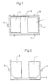
- FIG. 1 shows a plan view of a first embodiment of the invention.
- the Electric gear unit of the drive arrangement shown comprises a Generator 1 and a drive motor 3.
- Generator 1 and drive motor 3 are arranged together in a support frame 5.
- the gear unit can be installed close to the wheel in the vehicle chassis.
- Generator 1 is over Wave 7 with the internal combustion engine, not shown
- Drive arrangement coupled drive motor 3, which is preferably a so-called transverse flux machine is, as for example in "A electric single wheel drive for city buses of the future ", B. Wüst, R. Müller, A. Lange, in “Der Nah strig, 6/94, Alba garverlag, Dadoreldort, pp. 1-7" or DE 37 05 089 described is via output shaft 9 with the nearby arranged, not shown, connected drive wheels.
- Output shaft 9 can act directly on the drive wheels or on an axle gear for example the rear wheels. But it would also be possible that Output shaft 9 acts on a planetary gear arranged in the wheel hub, as disclosed for
- Electricity can also be provided from a drive motor Energy storage, such as a battery to feed.
- a drive motor Energy storage such as a battery to feed.
- the drive motors are supplied, for example, from the text "Drive systems with permanent magnet synchronous motors, automotive Engineering, February 1995, pp. 75-79 ".
- the outside of that surrounded by a support frame 5 Electric transmission unit arranged energy storage is not in Figure 1 shown in more detail.
- Fasteners are on the support frame 5, For example, attachment points 11 are provided. These attachment points match the attachment points of one conventional automatic transmission in the vehicle chassis. It is particularly easy, the summarized in the support frame 5 replace the electrical gear unit with an automatic transmission.
- the for an automatic transmission already used drive shaft 7 and Output shaft 9 must therefore only with the instead of the automatic transmission electrical gear unit can be connected.
- Carrier frame 5 also the electrical or electronic components, such as for example, inverters etc. are accommodated.
- electrical or electronic components such as for example, inverters etc.
- the present exemplary embodiment in the space 13 indicated by dash-dotted lines be arranged between generator 1 and drive motor 3.
- Figure 2 shows the embodiment of an electrical transmission unit according to Figure 1 in a side view. It is particularly easy to recognize Carrier frame 5, which accommodates both generator 1 and traction motor 3. Good can also be seen the drive shaft 7, the internal combustion engine and generator connects with each other and the output shaft 9, which from the drive motor to the Driving wheels work.
- Carrier frame 5 is in the present embodiment open trough-shaped. Of course, for the Those skilled in the art can also use other embodiments than the one shown open top frame 5, conceivable. For example, the carrier frame also completely closed or segmented from a skeleton be composed.
- FIG. 3 shows a further embodiment of an electrical transmission unit shown with carrier frame in plan view
- the electrical gear unit comprises a generator 1 and two traction motors 3.1, 3.2.
- everyone who Traction motors 3.1, 3.2 act on an output shaft 9.1, 9.2, which in turn the Drives wheels.
- the output shaft is designated as 7 in Figure 1, in the same reference numerals apply to the same components as in FIGS. 1 and 2.
- the embodiment shown in Figure 4 comprises several drive motors. Again, generator 1 and the drive motors 3.1 and 3.2 are in one common support frame 5 arranged. Generator 1 is by Drive shaft 7 driven by the internal combustion engine. The electric current is led to the traction motors or drive motors 3.1 and 3.2. The Drive motors 3.1 and 3.2 work together on the also in Carrier frame arranged summing gear 15. The two Drive motors 3.1 and 3.2 thus work on the summing gear 15 on the common output shaft 9, which in turn is connected to the drive wheels is
- FIGS. 5 and 6 show further variants of the invention with only one Drive motor 3 shown per transmission unit according to the invention.
- the drive motor 3 is gear 17 that on Drive shaft 9 acts, downstream.
- Gear 17 is like generator 1 and Drive motor 3 housed within the frame 5.
- Gear 17 can also be provided a torque converter.
- the Generator 1 is preceded by another gear 19. This gear 19 can be used to adjust the speed between gearbox and drive motor.
- FIG. 6 shows an arrangement of the invention, in which due to the Installation conditions an arrangement offset by any angle was chosen between generator 1 and drive motor 3. In the illustrated embodiment, this angle is 90 °.
- the 90 ° arrangement is particularly suitable for Vehicles with transversely installed internal combustion engine, which at conventional gearbox an angular drive between gearbox and axle would need.
- gearbox on the output side compared to the generator or the drive motor to offset any arbitrary angle.
- two such gear units could be arranged side by side, each individual transmission unit according to the invention in its own Carrier frame is arranged.
- FIGS. 7 to 11 show how the embodiments according to FIGS Figures 1 to 6, a variety of different arrangements of the individual components of the gear unit in a self-supporting Construction.
- the same components as in Figures 1 to 6 are also in Figures 7 to 11 with the same reference numerals.
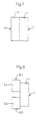
- Figure 7 shows a first embodiment of the self-supporting structure.
- the illustrated electrical gear unit of the drive arrangement comprises a generator 1 and a drive motor 3.
- generator 1 and Drive motor 3 are connected to each other in a self-supporting manner.
- the Gear unit can be installed close to the wheel in the vehicle chassis.
- Generator 1 is via shaft 7 with the internal combustion engine, not shown coupled to the drive arrangement.
- Drive motor 3 which is preferably a is so-called transverse flux machine, is via output shaft 9 with the in the nearby arranged, not shown, drive wheels connected.
- Output shaft 9 can act directly on the drive wheels or via one Axle gear on the rear wheels, for example. But it would also be possible that output shaft 9 on a planetary gear arranged in the wheel hub acts.
- Electricity can also be provided from a drive motor To supply energy storage, for example a battery.
- the Energy storage is not shown in Figure 7.
- the self-supporting Construction includes fasteners. These attachment points of the fasteners are as with the Construction with support frame arranged so that it with the Attachment points of a conventional automatic transmission in the Vehicle chassis match. It is particularly easy because of that replace the electrical gear unit with an automatic transmission. The for an automatic transmission already used drive shaft 7 and Output shaft 9 must then only with the instead of the automatic transmission electrical gear unit can be connected.
- Figure 8 shows a second embodiment of a self-supporting electrical Gear unit shown in top view.
- This embodiment draws are characterized in that the electrical gear unit a generator 1 and includes two traction motors 3.1, 3.2. Each of the traction motors 3.1, 3.2 acts an output shaft 9.1, 9.2, which in turn drives the wheels.
- the output shaft is designated as 7 in FIG. 7, otherwise the same applies to the same components same reference numerals as in Figures 1 to 7.
- FIG 9 is another embodiment of a self-supporting electrical Gear unit shown with several drive motors.
- Generator 1 will driven by drive shaft 7 from the internal combustion engine.
- the electric one Current is fed to the traction motors or drive motors 3.1 and 3.2.
- the drive motors 3.1 and 3.2 act together on Summation gear 15.
- the two drive motors 3.1 and 3.2 thus work via summation gear 15 on the common output shaft 9, which in turn is connected to the drive wheels.
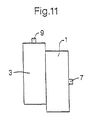
- Figures 10 and 11 are further variants of the self-supporting Embodiment with only one drive motor 3 per inventive Gear unit shown.
- the self-supporting Embodiment a generator 1 and drive motor 3.
- the Drive motor 3 is subordinate to gear 17, which acts on drive shaft 9.
- a torque converter can also be provided his.
- the generator 1 is preceded by another transmission 19. This Gear 19 can adjust the speed between gear and Serve drive motor.
- FIG 11 shows an arrangement of the invention, in which due to the Installation conditions an arrangement offset by any angle was chosen between generator 1 and drive motor 3. In the illustrated embodiment, this angle is 90 °.
- the 90 ° arrangement is particularly suitable for Vehicles with transversely installed internal combustion engine, which at conventional gearbox an angular drive between gearbox and axle would need.
- gearbox on the output side compared to the generator or the drive motor to offset any arbitrary angle.
- two such gear units could be arranged side by side, each individual transmission unit according to the invention in its own Carrier frame is arranged.
- an electric transmission unit is thus the first time presented that easily exchange with a conventional automatic transmission allowed.
- the possibility of pre-assembly should be mentioned. Due to the pre-assembly, the logical effort for the Users, for example the commercial vehicle manufacturer, considerably. In one more advantageous embodiment can be provided that the Cooling water pipes are also pre-assembled, so that the effort for this considerably simplified compared to conventional arrangements.
Landscapes
- Engineering & Computer Science (AREA)
- Transportation (AREA)
- Mechanical Engineering (AREA)
- Chemical & Material Sciences (AREA)
- Combustion & Propulsion (AREA)
- Power Engineering (AREA)
- Life Sciences & Earth Sciences (AREA)
- Sustainable Development (AREA)
- Sustainable Energy (AREA)
- Arrangement Of Transmissions (AREA)
- Hybrid Electric Vehicles (AREA)
- Electric Propulsion And Braking For Vehicles (AREA)
- Connection Of Motors, Electrical Generators, Mechanical Devices, And The Like (AREA)
Description
- Fig. 1
- eine Draufsicht auf eine Getriebeeinheit gemäß der Erfindung mit einem Trägerrahmen gemäß einer ersten Ausführungsform der Erfindung;
- Fig. 2
- eine Seitenansicht der ersten Ausführungsform der Getriebeeinheit mit Trägerrahmen gemäß Fig. 1;
- Fig. 3
- eine Draufsicht auf eine zweite Ausführungsform der Erfindung, wobei die in einem Trägerrahmen gelagerte Getriebeeinheit zwei Fahrmotoren aufweist;
- Fig. 4
- eine Draufsicht auf eine weitere Ausführungsform der Erfindung, wobei die Getriebeeinheit in einem Trägerrahmen gelagerte mehrere Fahrmotoren und ein Summiergetriebe umfaßt;
- Fig. 5
- eine Draufsicht auf eine Ausführungsform der Erfindung, wobei die in einem Trägerrahmen gelagerte Getriebeeinheit einen Fahrmotor und ein nachgeordnetes Getriebe umfaßt;
- Fig. 6
- eine Draufsicht auf eine weitere Ausführungsform der Erfindung, wobei die in einem Trägerrahmen gelagerte Getriebeeinheit einen Generator und einen um 90° hierzu versetzten Fahrmotor umfaßt;
- Fig. 7
- eine selbsttragende Getriebeeinheit umfassend einen Antriebsmotor und einen Generator;
- Fig. 8
- eine selbsttragende Getriebeeinheit umfassend zwei Fahrmotoren;
- Fig. 9
- eine selbsttrageride Getriebeeinheit umfassend mehrere Fahrmotoren und ein Summiergetriebe;
- Fig. 10
- eine selbsttragende Getriebeeinheit umfassend ein Fahrmotor und ein nachgeordnetes Getriebe;
- Fig. 11
- eine selbsttragende Getriebeeinheit umfassend einen Generator und einen um 90° hierzu versetzten Fahrmotor.
Claims (11)
- Elektrische Getriebeeinheit zur Montage in einem Fahrzeug mit mindestens einem Verbrennungsmotor, umfassend mindestens einen Antriebsmotor (3) und mindestens einen Generator (1), wobei die elektrische Getriebeeinheit austauschbar im Chassis eines Kraftfahrzeuges angeordnet ist,
dadurch gekennzeichnet, daß die Getriebeeinheit selbsttragend mit Befestigungspunkten (11) ausgebildet ist oder einen Trägerrahmen mit Befestigungspunkten (11) umfaßt und daß die Getriebeeinheit äußere Abmessungen aufweist, die denen eines Automatikgetriebes bezüglich der Einbaumaße entsprechen, wobei die Befestigungspunkte (11) derart angeordnet sind, daß die für ein Getriebe vorgesehenen Befestigungsstellen in einem Fahrzeuggestell für die elektrische Getriebeeinheit verwendet werden können. - Antriebsanordnung für ein Fahrzeug mit2.1 mindestens einem Verbrennungsmotor,2.2 mindestens einem Generator (1);2.3 mindestens einem Antriebsmotor (3), wobei2.4 mindestens ein Generator und mindestens ein Antriebsmotor mindestens zu einer austauschbaren elektrischen Getriebeeinheit zusammengefaßt sind,
dadurch gekennzeichnet, daß2.5 die elektrische Getriebeeinheit selbsttragend mit Befestigungspunkten (11) ausgebildet ist oder einen Trägerrahmen mit Befestigungspunkten (11) umfaßt und die elektrische Getriebeeinheit Abmessungen aufweist, die denen eines Automatikgetriebes bezüglich der Einbaumaße entsprechen und daß2.6 die Getriebeeinheit räumlich in der Nähe der anzutreibenden Achse und/oder Räder angeordnet ist, wobei2.7 die Befestigungspunkte (11) derart angeordnet sind, daß die für ein Getriebe vorgesehenen Befestigungsstellen in einem Fahrzeuggestell für die elektrische Getriebeeinheit verwendet werden können. - Antriebsanordnung nach Anspruch 2, dadurch gekennzeichnet, daß die elektrischen beziehungsweise elektronischen Komponenten für die Getriebeeinheit von der Getriebeeinheit umfaßt werden.
- Antriebsanordnung nach Anspruch 3, dadurch gekennzeichnet, daß die elektrischen beziehungsweise elektronischen Komponenten für die Getriebeeinheit an den Befestigungspunkten angeordnet sind.
- Antriebsanordnung nach einem der Ansprüche 2 bis 4, dadurch gekennzeichnet, daß die Getriebeeinheit ein dem Generator (1) vorgeschaltetes Getriebe zur Drehzahlanpassung von Generator (1) und Verbrennungsmotor umfaßt.
- Antriebsordnung nach einem der Ansprüche 2 bis 5, dadurch gekennzeichnet, daß die Getriebeeinheit mehrere Antriebsmotoren umfaßt.
- Antriebsanordnung nach Anspruch 6, dadurch gekennzeichnet, daß mehrere Antriebsmotoren über ein Summiergetriebe auf eine gemeinsame Abtriebswelle arbeiten.
- Antriebsanordnung gemäß Anspruch 6, dadurch gekennzeichnet, daß die elektrische Getriebeeinheit zwei Antriebsmotoren (3.1, 3.2) umfaßt, die derart angeordnet sind, daß über die Abtriebswellen (9.1, 9.2) die Räder/Achsen angetrieben werden können.
- Getriebeeinheit nach Anspruch 1 bzw. Antriebsanordnung nach einem der Ansprüche 2 bis 5, dadurch gekennzeichnet, daß dem Antriebsmotor ein Getriebe (15) nachgeschaltet ist.
- Getriebeeinheit nach Anspruch 1 bzw. Antriebsanordnung nach einem der Ansprüche 2 bis 9, dadurch gekennzeichnet, daß der oder die Antriebsmotor(en) und/oder das abtriebsseitige Getriebe gegenüber dem Generator um einen Winkel versetzt angeordnet ist.
- Getriebeeinheit nach Anspruch 1 bzw. Antriebsanordnung nach einem der Ansprüche 2 bis 10, dadurch gekennzeichnet, daß die Antriebsanordnung des weiteren einen Energiespeicher zur Versorgung der Antriebsmotoren umfaßt.
Priority Applications (1)
| Application Number | Priority Date | Filing Date | Title |
|---|---|---|---|
| EP02022197A EP1270304A3 (de) | 1997-07-10 | 1998-07-10 | Elektrische Getriebeeinheit |
Applications Claiming Priority (5)
| Application Number | Priority Date | Filing Date | Title |
|---|---|---|---|
| DE19729378 | 1997-07-10 | ||
| DE19729378 | 1997-07-10 | ||
| DE19756083 | 1997-12-17 | ||
| DE19756083A DE19756083A1 (de) | 1997-07-10 | 1997-12-17 | Elektrische Getriebeeinheit |
| PCT/EP1998/004306 WO1999002358A1 (de) | 1997-07-10 | 1998-07-10 | Elektrische getriebeeinheit |
Related Child Applications (1)
| Application Number | Title | Priority Date | Filing Date |
|---|---|---|---|
| EP02022197A Division EP1270304A3 (de) | 1997-07-10 | 1998-07-10 | Elektrische Getriebeeinheit |
Publications (2)
| Publication Number | Publication Date |
|---|---|
| EP0993385A1 EP0993385A1 (de) | 2000-04-19 |
| EP0993385B1 true EP0993385B1 (de) | 2003-04-09 |
Family
ID=26038154
Family Applications (1)
| Application Number | Title | Priority Date | Filing Date |
|---|---|---|---|
| EP98941316A Expired - Lifetime EP0993385B1 (de) | 1997-07-10 | 1998-07-10 | Elektrische getriebeeinheit |
Country Status (4)
| Country | Link |
|---|---|
| EP (1) | EP0993385B1 (de) |
| AT (1) | ATE236806T1 (de) |
| CA (1) | CA2296541A1 (de) |
| WO (1) | WO1999002358A1 (de) |
Families Citing this family (5)
| Publication number | Priority date | Publication date | Assignee | Title |
|---|---|---|---|---|
| US20010052433A1 (en) * | 2000-04-14 | 2001-12-20 | Harris Donald B. | Hybrid power supply module |
| US20020084120A1 (en) * | 2001-01-02 | 2002-07-04 | Beasley Leslie R. | Motor assembly with independent motor units |
| US20030070850A1 (en) | 2001-02-16 | 2003-04-17 | Cellex Power Products, Inc. | Hybrid power supply apparatus for battery replacement applications |
| ITMI20091616A1 (it) * | 2009-09-23 | 2011-03-24 | Sts Srl | Dispositivo riduttore o moltiplicatore di giri elettronico |
| CN103879283B (zh) * | 2014-03-10 | 2019-01-15 | 浙江吉利汽车研究院有限公司 | 一种电动车辆 |
Citations (1)
| Publication number | Priority date | Publication date | Assignee | Title |
|---|---|---|---|---|
| DE4230529A1 (de) * | 1992-09-12 | 1994-03-17 | Opel Adam Ag | Kraftfahrzeug mit auswechselbarem Heckmotormodul |
Family Cites Families (4)
| Publication number | Priority date | Publication date | Assignee | Title |
|---|---|---|---|---|
| US4593786A (en) * | 1982-05-03 | 1986-06-10 | John Tate | Self-contained power supply and support therefor |
| GB2176852B (en) * | 1985-06-20 | 1989-07-26 | Westinghouse Electric Corp | Transmission with a speed reducer and gear shifter |
| DE3620362A1 (de) * | 1986-06-18 | 1987-12-23 | Magnet Motor Gmbh | Kraftfahrzeug |
| DE4134160A1 (de) * | 1991-10-11 | 1993-04-22 | Mannesmann Ag | Kraftfahrzeug und verfahren zum betrieb dieses kraftfahrzeugs |
-
1998
- 1998-07-10 EP EP98941316A patent/EP0993385B1/de not_active Expired - Lifetime
- 1998-07-10 AT AT98941316T patent/ATE236806T1/de not_active IP Right Cessation
- 1998-07-10 CA CA002296541A patent/CA2296541A1/en not_active Abandoned
- 1998-07-10 WO PCT/EP1998/004306 patent/WO1999002358A1/de not_active Ceased
Patent Citations (1)
| Publication number | Priority date | Publication date | Assignee | Title |
|---|---|---|---|---|
| DE4230529A1 (de) * | 1992-09-12 | 1994-03-17 | Opel Adam Ag | Kraftfahrzeug mit auswechselbarem Heckmotormodul |
Also Published As
| Publication number | Publication date |
|---|---|
| ATE236806T1 (de) | 2003-04-15 |
| WO1999002358A1 (de) | 1999-01-21 |
| CA2296541A1 (en) | 1999-01-21 |
| EP0993385A1 (de) | 2000-04-19 |
Similar Documents
| Publication | Publication Date | Title |
|---|---|---|
| DE69702231T2 (de) | Serien- Hybrid- Fahrzeug und Antriebseinheit dafür | |
| EP1926622B1 (de) | Antriebssystem für ein landwirtschaftliches oder industrielles nutzfahrzeug | |
| DE102012025371B4 (de) | Kraftfahrzeug | |
| DE4335849C1 (de) | Antriebseinrichtung für ein Verkehrsmittel | |
| DE19850606B4 (de) | Kettenfahrzeug | |
| DE112020003857T5 (de) | Fahrzeugantriebsvorrichtung | |
| DE102010049608B4 (de) | Radantriebsanordnung und Antriebssystem mit Radantriebsanordnung | |
| EP0249806B1 (de) | Kraftfahrzeug | |
| DE2805932A1 (de) | Gesamtelektrischer, modularer traktor, insbesondere fuer die landwirtschaft | |
| DE102008030581A1 (de) | Triebstrang für ein Kraftfahrzeug und Verfahren zum Betreiben eines Triebstrangs eines Kraftfahrzeuges | |
| DE102007032635A1 (de) | Nutzung des Massenspielraums bei Schienenfahrzeugen mit Verbrennungsmotoren hoher Leistungsdichte | |
| DE102021203379A1 (de) | Kühlanordnung für eine elektrische antriebsbaugruppeeines arbeitsfahrzeugs | |
| DE102008061945A1 (de) | Elektrische Achsantriebseinheit mit variabler Momentenverteilung | |
| DE10222812A1 (de) | Elektrisches Lenk-Antriebssystem für ein Fahrzeug mit Radseitenlenkung | |
| EP2218603A1 (de) | Hybridantrieb | |
| EP0993385B1 (de) | Elektrische getriebeeinheit | |
| DE4306381C2 (de) | Hybridantrieb für ein Kraftfahrzeug | |
| EP0125320A1 (de) | Verwendung eines Fahrzeugs als Stromerzeugungsaggregat für fahrzeugfremde Stromverbraucher | |
| DE102020115665A1 (de) | Fahrzeugantrieb für Hybridfahrzeuge mit Brennkraftmaschinen und elektrischen Maschinen | |
| EP1270304A2 (de) | Elektrische Getriebeeinheit | |
| DE10129152B4 (de) | Antriebsbaugruppe und Antriebsvorrichtung für Fahrzeuge | |
| DE102020207101A1 (de) | Elektrischer Antrieb | |
| DE102021213150A1 (de) | Abdeckung für eine elektrische achsanordnung | |
| DE102021124284A1 (de) | Strebenbaugruppe für ein modul eines elektrifizierten fahrzeugs und stützverfahren | |
| DE102023103953A1 (de) | Elektrisch betreibbarer Achsantriebsstrang und Kit-of-Parts |
Legal Events
| Date | Code | Title | Description |
|---|---|---|---|
| PUAI | Public reference made under article 153(3) epc to a published international application that has entered the european phase |
Free format text: ORIGINAL CODE: 0009012 |
|
| 17P | Request for examination filed |
Effective date: 19991211 |
|
| AK | Designated contracting states |
Kind code of ref document: A1 Designated state(s): AT BE CH DE ES FR GB IT LI NL SE |
|
| 17Q | First examination report despatched |
Effective date: 20010827 |
|
| GRAH | Despatch of communication of intention to grant a patent |
Free format text: ORIGINAL CODE: EPIDOS IGRA |
|
| GRAH | Despatch of communication of intention to grant a patent |
Free format text: ORIGINAL CODE: EPIDOS IGRA |
|
| GRAA | (expected) grant |
Free format text: ORIGINAL CODE: 0009210 |
|
| AK | Designated contracting states |
Designated state(s): AT BE CH DE ES FR GB IT LI NL SE |
|
| PG25 | Lapsed in a contracting state [announced via postgrant information from national office to epo] |
Ref country code: NL Free format text: LAPSE BECAUSE OF FAILURE TO SUBMIT A TRANSLATION OF THE DESCRIPTION OR TO PAY THE FEE WITHIN THE PRESCRIBED TIME-LIMIT Effective date: 20030409 Ref country code: IT Free format text: LAPSE BECAUSE OF FAILURE TO SUBMIT A TRANSLATION OF THE DESCRIPTION OR TO PAY THE FEE WITHIN THE PRESCRIBED TIME-LIMIT;WARNING: LAPSES OF ITALIAN PATENTS WITH EFFECTIVE DATE BEFORE 2007 MAY HAVE OCCURRED AT ANY TIME BEFORE 2007. THE CORRECT EFFECTIVE DATE MAY BE DIFFERENT FROM THE ONE RECORDED. Effective date: 20030409 Ref country code: GB Free format text: LAPSE BECAUSE OF FAILURE TO SUBMIT A TRANSLATION OF THE DESCRIPTION OR TO PAY THE FEE WITHIN THE PRESCRIBED TIME-LIMIT Effective date: 20030409 Ref country code: FR Free format text: LAPSE BECAUSE OF FAILURE TO SUBMIT A TRANSLATION OF THE DESCRIPTION OR TO PAY THE FEE WITHIN THE PRESCRIBED TIME-LIMIT Effective date: 20030409 |
|
| REG | Reference to a national code |
Ref country code: GB Ref legal event code: FG4D Free format text: NOT ENGLISH |
|
| REG | Reference to a national code |
Ref country code: CH Ref legal event code: EP |
|
| PG25 | Lapsed in a contracting state [announced via postgrant information from national office to epo] |
Ref country code: SE Free format text: LAPSE BECAUSE OF FAILURE TO SUBMIT A TRANSLATION OF THE DESCRIPTION OR TO PAY THE FEE WITHIN THE PRESCRIBED TIME-LIMIT Effective date: 20030709 |
|
| PG25 | Lapsed in a contracting state [announced via postgrant information from national office to epo] |
Ref country code: AT Free format text: LAPSE BECAUSE OF NON-PAYMENT OF DUE FEES Effective date: 20030710 |
|
| PG25 | Lapsed in a contracting state [announced via postgrant information from national office to epo] |
Ref country code: LI Free format text: LAPSE BECAUSE OF NON-PAYMENT OF DUE FEES Effective date: 20030731 Ref country code: CH Free format text: LAPSE BECAUSE OF NON-PAYMENT OF DUE FEES Effective date: 20030731 Ref country code: BE Free format text: LAPSE BECAUSE OF NON-PAYMENT OF DUE FEES Effective date: 20030731 |
|
| NLV1 | Nl: lapsed or annulled due to failure to fulfill the requirements of art. 29p and 29m of the patents act | ||
| GBV | Gb: ep patent (uk) treated as always having been void in accordance with gb section 77(7)/1977 [no translation filed] |
Effective date: 20030409 |
|
| PG25 | Lapsed in a contracting state [announced via postgrant information from national office to epo] |
Ref country code: ES Free format text: LAPSE BECAUSE OF FAILURE TO SUBMIT A TRANSLATION OF THE DESCRIPTION OR TO PAY THE FEE WITHIN THE PRESCRIBED TIME-LIMIT Effective date: 20031030 |
|
| BERE | Be: lapsed |
Owner name: *VOITH TURBO G.M.B.H. & CO. K.G. Effective date: 20030731 |
|
| PLBE | No opposition filed within time limit |
Free format text: ORIGINAL CODE: 0009261 |
|
| STAA | Information on the status of an ep patent application or granted ep patent |
Free format text: STATUS: NO OPPOSITION FILED WITHIN TIME LIMIT |
|
| REG | Reference to a national code |
Ref country code: CH Ref legal event code: PL |
|
| EN | Fr: translation not filed | ||
| 26N | No opposition filed |
Effective date: 20040112 |
|
| PGFP | Annual fee paid to national office [announced via postgrant information from national office to epo] |
Ref country code: DE Payment date: 20110804 Year of fee payment: 14 |
|
| PG25 | Lapsed in a contracting state [announced via postgrant information from national office to epo] |
Ref country code: DE Free format text: LAPSE BECAUSE OF NON-PAYMENT OF DUE FEES Effective date: 20130201 |
|
| REG | Reference to a national code |
Ref country code: DE Ref legal event code: R119 Ref document number: 59807878 Country of ref document: DE Effective date: 20130201 |