EP0994201A2 - Procédé de traitement de la surface d'outils - Google Patents
Procédé de traitement de la surface d'outils Download PDFInfo
- Publication number
- EP0994201A2 EP0994201A2 EP99120242A EP99120242A EP0994201A2 EP 0994201 A2 EP0994201 A2 EP 0994201A2 EP 99120242 A EP99120242 A EP 99120242A EP 99120242 A EP99120242 A EP 99120242A EP 0994201 A2 EP0994201 A2 EP 0994201A2
- Authority
- EP
- European Patent Office
- Prior art keywords
- layer
- carbide
- carbides
- primary
- cvd
- Prior art date
- Legal status (The legal status is an assumption and is not a legal conclusion. Google has not performed a legal analysis and makes no representation as to the accuracy of the status listed.)
- Withdrawn
Links
- 238000000034 method Methods 0.000 title claims abstract description 50
- 238000004381 surface treatment Methods 0.000 title claims description 5
- 150000001247 metal acetylides Chemical class 0.000 claims abstract description 68
- 239000000463 material Substances 0.000 claims abstract description 63
- 229910000831 Steel Inorganic materials 0.000 claims abstract description 59
- 239000010959 steel Substances 0.000 claims abstract description 59
- 239000011159 matrix material Substances 0.000 claims abstract description 39
- 230000008569 process Effects 0.000 claims abstract description 27
- 238000000151 deposition Methods 0.000 claims abstract description 10
- 239000010410 layer Substances 0.000 claims description 143
- 238000000576 coating method Methods 0.000 claims description 31
- 239000011248 coating agent Substances 0.000 claims description 23
- 239000007789 gas Substances 0.000 claims description 11
- 239000000853 adhesive Substances 0.000 claims description 10
- 230000001070 adhesive effect Effects 0.000 claims description 10
- 230000015572 biosynthetic process Effects 0.000 claims description 10
- 230000008021 deposition Effects 0.000 claims description 9
- 229910001315 Tool steel Inorganic materials 0.000 claims description 8
- 239000000314 lubricant Substances 0.000 claims description 6
- 238000005461 lubrication Methods 0.000 claims description 6
- 238000005275 alloying Methods 0.000 claims description 4
- 238000004873 anchoring Methods 0.000 claims description 4
- 238000009499 grossing Methods 0.000 claims description 4
- 239000007788 liquid Substances 0.000 claims description 4
- 238000005121 nitriding Methods 0.000 claims description 4
- 238000007789 sealing Methods 0.000 claims description 4
- 229910045601 alloy Inorganic materials 0.000 claims description 3
- 239000000956 alloy Substances 0.000 claims description 3
- 230000012010 growth Effects 0.000 claims description 3
- 239000007787 solid Substances 0.000 claims description 3
- 229910052582 BN Inorganic materials 0.000 claims description 2
- PZNSFCLAULLKQX-UHFFFAOYSA-N Boron nitride Chemical compound N#B PZNSFCLAULLKQX-UHFFFAOYSA-N 0.000 claims description 2
- CWQXQMHSOZUFJS-UHFFFAOYSA-N molybdenum disulfide Chemical compound S=[Mo]=S CWQXQMHSOZUFJS-UHFFFAOYSA-N 0.000 claims description 2
- 229910052982 molybdenum disulfide Inorganic materials 0.000 claims description 2
- 230000036961 partial effect Effects 0.000 claims description 2
- 239000000470 constituent Substances 0.000 claims 3
- 238000006243 chemical reaction Methods 0.000 claims 1
- 238000005530 etching Methods 0.000 claims 1
- 239000012791 sliding layer Substances 0.000 claims 1
- 230000007547 defect Effects 0.000 description 12
- 230000000694 effects Effects 0.000 description 9
- 239000000203 mixture Substances 0.000 description 9
- 239000012071 phase Substances 0.000 description 8
- 239000011324 bead Substances 0.000 description 7
- 238000005498 polishing Methods 0.000 description 7
- 230000002829 reductive effect Effects 0.000 description 7
- 238000005520 cutting process Methods 0.000 description 6
- 238000011065 in-situ storage Methods 0.000 description 6
- 238000003754 machining Methods 0.000 description 6
- 230000035882 stress Effects 0.000 description 6
- 239000000758 substrate Substances 0.000 description 6
- 239000003792 electrolyte Substances 0.000 description 5
- 239000002131 composite material Substances 0.000 description 4
- 238000005516 engineering process Methods 0.000 description 4
- 230000001965 increasing effect Effects 0.000 description 4
- 239000004033 plastic Substances 0.000 description 4
- 229920003023 plastic Polymers 0.000 description 4
- 238000012545 processing Methods 0.000 description 4
- 238000011282 treatment Methods 0.000 description 4
- 238000011144 upstream manufacturing Methods 0.000 description 4
- HEMHJVSKTPXQMS-UHFFFAOYSA-M Sodium hydroxide Chemical compound [OH-].[Na+] HEMHJVSKTPXQMS-UHFFFAOYSA-M 0.000 description 3
- RTAQQCXQSZGOHL-UHFFFAOYSA-N Titanium Chemical compound [Ti] RTAQQCXQSZGOHL-UHFFFAOYSA-N 0.000 description 3
- 230000006378 damage Effects 0.000 description 3
- 239000007791 liquid phase Substances 0.000 description 3
- 239000010936 titanium Substances 0.000 description 3
- 229910052719 titanium Inorganic materials 0.000 description 3
- IJGRMHOSHXDMSA-UHFFFAOYSA-N Atomic nitrogen Chemical compound N#N IJGRMHOSHXDMSA-UHFFFAOYSA-N 0.000 description 2
- 229910000997 High-speed steel Inorganic materials 0.000 description 2
- 239000000919 ceramic Substances 0.000 description 2
- 238000004140 cleaning Methods 0.000 description 2
- 239000010432 diamond Substances 0.000 description 2
- 229910003460 diamond Inorganic materials 0.000 description 2
- 229910052751 metal Inorganic materials 0.000 description 2
- 239000002184 metal Substances 0.000 description 2
- 239000012429 reaction media Substances 0.000 description 2
- 238000007788 roughening Methods 0.000 description 2
- 239000000126 substance Substances 0.000 description 2
- 238000012876 topography Methods 0.000 description 2
- 229920001817 Agar Polymers 0.000 description 1
- 229910018072 Al 2 O 3 Inorganic materials 0.000 description 1
- 229910000851 Alloy steel Inorganic materials 0.000 description 1
- ZOXJGFHDIHLPTG-UHFFFAOYSA-N Boron Chemical compound [B] ZOXJGFHDIHLPTG-UHFFFAOYSA-N 0.000 description 1
- OKTJSMMVPCPJKN-UHFFFAOYSA-N Carbon Chemical compound [C] OKTJSMMVPCPJKN-UHFFFAOYSA-N 0.000 description 1
- ZAMOUSCENKQFHK-UHFFFAOYSA-N Chlorine atom Chemical compound [Cl] ZAMOUSCENKQFHK-UHFFFAOYSA-N 0.000 description 1
- VYZAMTAEIAYCRO-UHFFFAOYSA-N Chromium Chemical compound [Cr] VYZAMTAEIAYCRO-UHFFFAOYSA-N 0.000 description 1
- 239000012670 alkaline solution Substances 0.000 description 1
- 229910052782 aluminium Inorganic materials 0.000 description 1
- XAGFODPZIPBFFR-UHFFFAOYSA-N aluminium Chemical compound [Al] XAGFODPZIPBFFR-UHFFFAOYSA-N 0.000 description 1
- 230000009286 beneficial effect Effects 0.000 description 1
- 230000008901 benefit Effects 0.000 description 1
- 238000005422 blasting Methods 0.000 description 1
- 229910052796 boron Inorganic materials 0.000 description 1
- 229910052799 carbon Inorganic materials 0.000 description 1
- 239000003518 caustics Substances 0.000 description 1
- 239000000460 chlorine Substances 0.000 description 1
- 229910052801 chlorine Inorganic materials 0.000 description 1
- 229910052804 chromium Inorganic materials 0.000 description 1
- 239000011651 chromium Substances 0.000 description 1
- 230000001143 conditioned effect Effects 0.000 description 1
- 230000003750 conditioning effect Effects 0.000 description 1
- 238000010276 construction Methods 0.000 description 1
- 238000005336 cracking Methods 0.000 description 1
- 230000001419 dependent effect Effects 0.000 description 1
- 230000009189 diving Effects 0.000 description 1
- 238000001035 drying Methods 0.000 description 1
- 230000006355 external stress Effects 0.000 description 1
- 230000002349 favourable effect Effects 0.000 description 1
- 239000010437 gem Substances 0.000 description 1
- 229910052735 hafnium Inorganic materials 0.000 description 1
- VBJZVLUMGGDVMO-UHFFFAOYSA-N hafnium atom Chemical compound [Hf] VBJZVLUMGGDVMO-UHFFFAOYSA-N 0.000 description 1
- 230000006872 improvement Effects 0.000 description 1
- 238000010348 incorporation Methods 0.000 description 1
- XEEYBQQBJWHFJM-UHFFFAOYSA-N iron Substances [Fe] XEEYBQQBJWHFJM-UHFFFAOYSA-N 0.000 description 1
- 229910052742 iron Inorganic materials 0.000 description 1
- JEIPFZHSYJVQDO-UHFFFAOYSA-N iron(III) oxide Inorganic materials O=[Fe]O[Fe]=O JEIPFZHSYJVQDO-UHFFFAOYSA-N 0.000 description 1
- 238000005304 joining Methods 0.000 description 1
- 239000002655 kraft paper Substances 0.000 description 1
- 230000009021 linear effect Effects 0.000 description 1
- 238000011068 loading method Methods 0.000 description 1
- 238000004519 manufacturing process Methods 0.000 description 1
- 230000003472 neutralizing effect Effects 0.000 description 1
- 229910052758 niobium Inorganic materials 0.000 description 1
- 239000010955 niobium Substances 0.000 description 1
- GUCVJGMIXFAOAE-UHFFFAOYSA-N niobium atom Chemical compound [Nb] GUCVJGMIXFAOAE-UHFFFAOYSA-N 0.000 description 1
- 150000004767 nitrides Chemical class 0.000 description 1
- 229910052757 nitrogen Inorganic materials 0.000 description 1
- 239000002245 particle Substances 0.000 description 1
- 230000002028 premature Effects 0.000 description 1
- 230000003405 preventing effect Effects 0.000 description 1
- 230000002035 prolonged effect Effects 0.000 description 1
- 239000011241 protective layer Substances 0.000 description 1
- 230000001603 reducing effect Effects 0.000 description 1
- 230000009467 reduction Effects 0.000 description 1
- 230000003578 releasing effect Effects 0.000 description 1
- 238000010099 solid forming Methods 0.000 description 1
- 239000000243 solution Substances 0.000 description 1
- 230000008093 supporting effect Effects 0.000 description 1
- 230000001629 suppression Effects 0.000 description 1
- 229910052715 tantalum Inorganic materials 0.000 description 1
- GUVRBAGPIYLISA-UHFFFAOYSA-N tantalum atom Chemical compound [Ta] GUVRBAGPIYLISA-UHFFFAOYSA-N 0.000 description 1
- XJDNKRIXUMDJCW-UHFFFAOYSA-J titanium tetrachloride Chemical compound Cl[Ti](Cl)(Cl)Cl XJDNKRIXUMDJCW-UHFFFAOYSA-J 0.000 description 1
- 238000012549 training Methods 0.000 description 1
- 230000007704 transition Effects 0.000 description 1
- 230000001960 triggered effect Effects 0.000 description 1
- WFKWXMTUELFFGS-UHFFFAOYSA-N tungsten Chemical compound [W] WFKWXMTUELFFGS-UHFFFAOYSA-N 0.000 description 1
- 229910052721 tungsten Inorganic materials 0.000 description 1
- 239000010937 tungsten Substances 0.000 description 1
- 229910052720 vanadium Inorganic materials 0.000 description 1
- LEONUFNNVUYDNQ-UHFFFAOYSA-N vanadium atom Chemical compound [V] LEONUFNNVUYDNQ-UHFFFAOYSA-N 0.000 description 1
- 238000003466 welding Methods 0.000 description 1
- -1 zicon Chemical compound 0.000 description 1
Images


Classifications
-
- C—CHEMISTRY; METALLURGY
- C23—COATING METALLIC MATERIAL; COATING MATERIAL WITH METALLIC MATERIAL; CHEMICAL SURFACE TREATMENT; DIFFUSION TREATMENT OF METALLIC MATERIAL; COATING BY VACUUM EVAPORATION, BY SPUTTERING, BY ION IMPLANTATION OR BY CHEMICAL VAPOUR DEPOSITION, IN GENERAL; INHIBITING CORROSION OF METALLIC MATERIAL OR INCRUSTATION IN GENERAL
- C23C—COATING METALLIC MATERIAL; COATING MATERIAL WITH METALLIC MATERIAL; SURFACE TREATMENT OF METALLIC MATERIAL BY DIFFUSION INTO THE SURFACE, BY CHEMICAL CONVERSION OR SUBSTITUTION; COATING BY VACUUM EVAPORATION, BY SPUTTERING, BY ION IMPLANTATION OR BY CHEMICAL VAPOUR DEPOSITION, IN GENERAL
- C23C14/00—Coating by vacuum evaporation, by sputtering or by ion implantation of the coating forming material
- C23C14/02—Pretreatment of the material to be coated
- C23C14/021—Cleaning or etching treatments
-
- C—CHEMISTRY; METALLURGY
- C23—COATING METALLIC MATERIAL; COATING MATERIAL WITH METALLIC MATERIAL; CHEMICAL SURFACE TREATMENT; DIFFUSION TREATMENT OF METALLIC MATERIAL; COATING BY VACUUM EVAPORATION, BY SPUTTERING, BY ION IMPLANTATION OR BY CHEMICAL VAPOUR DEPOSITION, IN GENERAL; INHIBITING CORROSION OF METALLIC MATERIAL OR INCRUSTATION IN GENERAL
- C23C—COATING METALLIC MATERIAL; COATING MATERIAL WITH METALLIC MATERIAL; SURFACE TREATMENT OF METALLIC MATERIAL BY DIFFUSION INTO THE SURFACE, BY CHEMICAL CONVERSION OR SUBSTITUTION; COATING BY VACUUM EVAPORATION, BY SPUTTERING, BY ION IMPLANTATION OR BY CHEMICAL VAPOUR DEPOSITION, IN GENERAL
- C23C16/00—Chemical coating by decomposition of gaseous compounds, without leaving reaction products of surface material in the coating, i.e. chemical vapour deposition [CVD] processes
- C23C16/02—Pretreatment of the material to be coated
- C23C16/0227—Pretreatment of the material to be coated by cleaning or etching
- C23C16/0236—Pretreatment of the material to be coated by cleaning or etching by etching with a reactive gas
-
- C—CHEMISTRY; METALLURGY
- C23—COATING METALLIC MATERIAL; COATING MATERIAL WITH METALLIC MATERIAL; CHEMICAL SURFACE TREATMENT; DIFFUSION TREATMENT OF METALLIC MATERIAL; COATING BY VACUUM EVAPORATION, BY SPUTTERING, BY ION IMPLANTATION OR BY CHEMICAL VAPOUR DEPOSITION, IN GENERAL; INHIBITING CORROSION OF METALLIC MATERIAL OR INCRUSTATION IN GENERAL
- C23F—NON-MECHANICAL REMOVAL OF METALLIC MATERIAL FROM SURFACE; INHIBITING CORROSION OF METALLIC MATERIAL OR INCRUSTATION IN GENERAL; MULTI-STEP PROCESSES FOR SURFACE TREATMENT OF METALLIC MATERIAL INVOLVING AT LEAST ONE PROCESS PROVIDED FOR IN CLASS C23 AND AT LEAST ONE PROCESS COVERED BY SUBCLASS C21D OR C22F OR CLASS C25
- C23F1/00—Etching metallic material by chemical means
Definitions
- the present invention relates to a method for surface treatment of tools made of tool steel, in their Matrix primary carbides are stored and tools, in whose steel matrix primary carbides are embedded, with a treated surface.
- high-performance tools have been coated with hard material for the purpose of maximum wear resistance. They exist e.g. B. of nitrides, carbides, carbonitrides and borides, formed at least from a metal from the group titanium, zicon, chromium, tungsten, tantalum, vanadium, niobium and hafnium, with at least one light element such as. For example, nitrogen, carbon, and the film deposition or boron. Is preferably carried out according to the CVD technique (CVD for C hemical V apour D eposition) or PVD (PVD for P hysical V apour D eposition).
- CVD technique CVD for C hemical V apour D eposition
- PVD PVD for P hysical V apour D eposition
- the tools are preferably made from ledeburitic cold work steels and high-performance high-speed steels (HSS). These steels can be adjusted to high hardness by suitable heat treatments and also have very hard carbides (in the steel matrix), which can be differentiated according to (large) primary and (small) secondary carbides. These carbides, especially the primary carbides, e.g. B. of the type M 7 C 3 , give these tool steels additional wear resistance, so that normally a large proportion of carbide is targeted by targeted steel alloy.
- HSS high-performance high-speed steels
- the present invention is based on the object identified, primary carbide-related defect potentials eliminate and provide a tool that an extremely resilient and wear-resistant Layer system of the highest reliability.
- the present invention relates to a method for surface treatment of tools made of tool steel, in their Steel matrix primary carbides are embedded, which is characterized in that uncovered on the surface and / or cut and / or protruding in relief Primary carbides forming a punctiform recessed surface detached or completely detached and a single or multi-layer on this surface Hard material layer is deposited.
- the present invention further relates to a tool made of tool steel, with primary carbides in its steel matrix are stored with a treated surface, which is characterized in that in the steel area near the edge the primary carbides at least by a predetermined amount 1 ⁇ m down to twice the layer thickness or entirely and the single or multi-layer CVD hard material layer these depressions or caverns together with components of the detached primary carbides perfectly fills out and thus punctiformly distributed, form-fitting There are layer anchorages in the base material, which the hard material layer additional shear strength and impart adhesive strength.
- the present invention also relates to a tool made of tool steel, with primary carbides in its steel matrix are stored with a treated surface, which is characterized in that in the steel area near the edge the primary carbides at least by a predetermined amount 1 ⁇ m to 4 ⁇ m and the PVD hard material layer lines or fills these depressions and thus point-distributed, form-fitting layer anchorages are present in the base material, which is the PVD hard material layer additional shear strength and Give adhesive strength.
- the load-bearing capacity of the composite system micro gearing is also to be increased between hard material layer and base material provided, as well as a nitriding of the edge Steel area.
- thermochemical Process specific gases set the primary carbides chemically and / or thermally to a predetermined Detach and or detach depth.
- the depth is in usually at least 1 ⁇ m to twice the layer thickness.
- the primary carbides are previously in one separate process galvanically in a liquid medium or chemically detached to a predetermined depth or detached.
- the depth should preferably be in the range of 1 ⁇ m are up to twice the layer thickness.
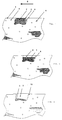
- FIG. 1 A still untreated surface of a tool is in Fig. 1 shown.
- machining-related cracks 7 formed also extend to the substrate surface.
- Reference numerals 5 indicates the machining direction.
- the primary carbide can also protrude from the substrate surface.
- Such a carbide relief 20 is shown in FIG. 11.
- the cut or uncovered primary carbides are removed to a predetermined depth after the mechanical processing of the functionally relevant work surfaces, that is to say after machining, lapping or polishing and before coating, and if appropriate also completely removed from the steel matrix close to the edge.
- the carbide can be removed in a separate treatment upstream of the coating or - as is only possible with the CVD process - also in the coating process itself.
- Electrolyte is the composition of the electrolyte to be chosen so that preferably only the primary carbides be dissolved or removed. Carbide removal and its Intensity, d. H. Speed and depth of cut about the chemical composition and concentration of the Electrolytes as well as current, bath temperature and Controlled diving time.
- area 8 is one shown electrolytically removed primary carbide.
- carbide removal in the liquid phase is that the items to be treated subsequently have different cleaning or neutralizing baths with subsequent intensive drying must go through, whereby the to be coated Surfaces rust or become contaminated in an uncontrolled manner can be what is not beneficial to the layer adhesion is.
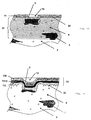
- PVD deposited layers are shown in FIGS. 4 and 5.
- the deposited hard material layer 11 is located on the substrate surface and forms trough-shaped depressions 12. It is typical of the PVD method that the gap 6 is not or only slightly filled, ie not is cemented "so that the notch effect persists.
- a load-increasing micro-toothing 22 and nitriding zone 23 are shown in Fig. 5.
- Fig. 8 shows an uncoated cutting edge 16 with an unfavorable primary carbide and processing-related gap 6.
- the shown in Fig. 9 PVD-coated cutting edge 17 shows the primary carbide, which is advantageously set back by partial detachment, but also shows, as in FIGS. 4 and 5, that gaps are not filled or cemented ", which creates a particularly critical defect formation here.
- Fig. 3 illustrates the advantages of carbide removal in CVD process.
- the edges 10 are also rounded to form a bead.
- the carbide detachment creates punctiform to small areas Deepening in the otherwise unchanged work surface, the depth of the carbides depending on Layer thickness, coating process, carbide formation and Stress is to be selected.
- the lowering depth should be in the Usually not significantly above 30% to 200% of the layer thickness go out, with reductions of about 1 to 2 microns represent the lower limit. Such amounts are quite possible the disadvantages of relief formation according to 5) and 6) mitigate enough, and the layer already a certain to provide additional support in the recesses.
- FIGS. 6 and 7 smoothen easily by diamond polishing. This is shown in Fig. 12, wherein a former bead 15 under Forming a rounded edge 21 has been smoothed is.
- the CVD-specific features explained under a) to f) allow defect-strategic measures to be taken within the broadest limits, especially specific to the base material and application.
- the steel composition and steel production as well as the dependent carbide formations (cast, forged or rolled), the type of stress (cutting, stamping, sheet metal forming, solid forming tools) and the workpiece material can be dealt with individually. So z. B. would - based on the "sealing effect" according to c) - make only a small carbide detachment if a sharp cutting edge is required.
- the has a defect-reduced PVD coating system are in steel area near the edge the primary carbides in predetermined Dimension reduced by at least 1 ⁇ m to 4 ⁇ m.
- the PVD hard material layer lines these recesses so that point-distributed, form-fitting layer anchorages are present in the base material, which is the PVD hard material layer additional shear strength and Give adhesive strength. This can be done by using a PVD coating upstream nitriding of the edge Steel range can also be increased.
- Example 1 Carbide removal for a PVD coating
- micro-roughening up to approx. 1/2 layer thickness can be carried out before or after the carbide removal and always before the PVD coating by fine-grain blasting with Al 2 O 3 or SiC particles.
- the steel area near the edge can be plasma nitrided to a depth of approx. 100 times the layer thickness.
- FIG. 13 An optimally designed tool surface with a PVD layer is shown schematically in Fig. 13.
- Carbide removal for CVD coatings is done in situ carried out, d. H. in the same coating process, in a temperature range of 800 - 1000 ° C in argon-hydrogen-HCl mixture.
- Time, temperature and gas composition decide on the removal intensity or depth and about the alloying, rounding, sealing and smoothing out the resulting carbide nests.
- the management of the Gas mixture under conditions of technical vacuum with correspondingly high gas speeds.
- the alloying and rounding or smoothing the carbide nests can be designed more or less intensively.
- the carbide nest walls being coated with components of the detached primary carbide are formed on the Edges of the depressions, roundings or linings, which, however, slightly bulge out into the substrate surface continue.
Landscapes
- Chemical & Material Sciences (AREA)
- Metallurgy (AREA)
- Chemical Kinetics & Catalysis (AREA)
- Engineering & Computer Science (AREA)
- Materials Engineering (AREA)
- Mechanical Engineering (AREA)
- Organic Chemistry (AREA)
- General Chemical & Material Sciences (AREA)
- Solid-Phase Diffusion Into Metallic Material Surfaces (AREA)
- Chemical Vapour Deposition (AREA)
- Other Surface Treatments For Metallic Materials (AREA)
- Powder Metallurgy (AREA)
- Cutting Tools, Boring Holders, And Turrets (AREA)
- Physical Vapour Deposition (AREA)
Applications Claiming Priority (2)
| Application Number | Priority Date | Filing Date | Title |
|---|---|---|---|
| DE19848025.3A DE19848025B4 (de) | 1998-10-17 | 1998-10-17 | Verfahren zur Oberflächenbehandlung von Werkzeugen und Werkzeuge mit behandelter Oberfläche |
| DE19848025 | 1998-10-17 |
Publications (2)
| Publication Number | Publication Date |
|---|---|
| EP0994201A2 true EP0994201A2 (fr) | 2000-04-19 |
| EP0994201A3 EP0994201A3 (fr) | 2002-08-07 |
Family
ID=7884874
Family Applications (1)
| Application Number | Title | Priority Date | Filing Date |
|---|---|---|---|
| EP99120242A Withdrawn EP0994201A3 (fr) | 1998-10-17 | 1999-10-11 | Procédé de traitement de la surface d'outils |
Country Status (4)
| Country | Link |
|---|---|
| US (1) | US20020025378A1 (fr) |
| EP (1) | EP0994201A3 (fr) |
| JP (1) | JP2000167720A (fr) |
| DE (1) | DE19848025B4 (fr) |
Cited By (1)
| Publication number | Priority date | Publication date | Assignee | Title |
|---|---|---|---|---|
| CN102181849A (zh) * | 2011-03-31 | 2011-09-14 | 大连交通大学 | 硬质合金刀具软涂层的制备方法 |
Families Citing this family (3)
| Publication number | Priority date | Publication date | Assignee | Title |
|---|---|---|---|---|
| DE102004057956A1 (de) * | 2004-11-30 | 2006-06-01 | Universität Augsburg | Verfahren zur Erhöhung der Verschleißfestigkeit von Hartstoffschichten, Vorrichtung zur Durchführung des Verfahrens und nach dem Verfahren hergestellte Hartstoffschichten |
| US20060226025A1 (en) * | 2005-03-16 | 2006-10-12 | Colorado School Of Mines | Electrochemical removal of die coatings |
| CN106077724B (zh) * | 2016-07-01 | 2018-08-21 | 江苏大学 | 一种固体润滑的金属切削刀具及其加工方法 |
Citations (1)
| Publication number | Priority date | Publication date | Assignee | Title |
|---|---|---|---|---|
| EP0447556A1 (fr) * | 1989-09-29 | 1991-09-25 | Sumitomo Electric Industries, Ltd. | Element dur rev tu en surface presentant d'excellentes caracteristiques de resistance a l'abrasion |
Family Cites Families (9)
| Publication number | Priority date | Publication date | Assignee | Title |
|---|---|---|---|---|
| US3171192A (en) * | 1961-09-22 | 1965-03-02 | Vitro Corp Of America | Article and method of fabricating same |
| CH540995A (de) * | 1971-03-22 | 1973-08-31 | Bbc Brown Boveri & Cie | Verfahren zum Aufbringen einer Schutzschicht auf einen Körper |
| US3767544A (en) * | 1971-09-02 | 1973-10-23 | Vermont American Corp | Surface treatment of high speed steel metal cutting tools and the product thereof |
| JPS5983718A (ja) * | 1982-11-05 | 1984-05-15 | Kobe Steel Ltd | 高速度鋼の表面処理方法 |
| JPS60154470A (ja) * | 1984-01-23 | 1985-08-14 | Toshiba Corp | 燃料電池 |
| US5314601A (en) * | 1989-06-30 | 1994-05-24 | Eltech Systems Corporation | Electrodes of improved service life |
| JP2770508B2 (ja) * | 1989-12-11 | 1998-07-02 | 住友電気工業株式会社 | 耐摩摺動部材 |
| US5560839A (en) * | 1994-06-27 | 1996-10-01 | Valenite Inc. | Methods of preparing cemented metal carbide substrates for deposition of adherent diamond coatings and products made therefrom |
| JPH10110720A (ja) * | 1996-10-08 | 1998-04-28 | Mitsubishi Motors Corp | 軸受け構造 |
-
1998
- 1998-10-17 DE DE19848025.3A patent/DE19848025B4/de not_active Expired - Fee Related
-
1999
- 1999-10-11 EP EP99120242A patent/EP0994201A3/fr not_active Withdrawn
- 1999-10-18 JP JP11295744A patent/JP2000167720A/ja active Pending
-
2001
- 2001-08-13 US US09/928,801 patent/US20020025378A1/en not_active Abandoned
Patent Citations (1)
| Publication number | Priority date | Publication date | Assignee | Title |
|---|---|---|---|---|
| EP0447556A1 (fr) * | 1989-09-29 | 1991-09-25 | Sumitomo Electric Industries, Ltd. | Element dur rev tu en surface presentant d'excellentes caracteristiques de resistance a l'abrasion |
Cited By (1)
| Publication number | Priority date | Publication date | Assignee | Title |
|---|---|---|---|---|
| CN102181849A (zh) * | 2011-03-31 | 2011-09-14 | 大连交通大学 | 硬质合金刀具软涂层的制备方法 |
Also Published As
| Publication number | Publication date |
|---|---|
| DE19848025A1 (de) | 2000-04-20 |
| DE19848025B4 (de) | 2015-02-05 |
| EP0994201A3 (fr) | 2002-08-07 |
| JP2000167720A (ja) | 2000-06-20 |
| US20020025378A1 (en) | 2002-02-28 |
Similar Documents
| Publication | Publication Date | Title |
|---|---|---|
| EP1721027B1 (fr) | Revetement pour outil de coupe et procede de production correspondant | |
| EP0925386B1 (fr) | Piece avec couche de protection contre l'usure | |
| DE102006029415B4 (de) | Verschleißfeste Beschichtung sowie Herstellverfahren hierfür | |
| EP2464761B1 (fr) | Segment de piston muni d'un revêtement. | |
| EP0155257B2 (fr) | Palier à contact lisse en métal composé | |
| DE4421144A1 (de) | Beschichtetes Werkzeug mit erhöhter Standzeit | |
| EP3155284A1 (fr) | Disque de frein pour véhicule automobile | |
| DE19824310C1 (de) | Gleitlager und Verfahren zu seiner Herstellung | |
| DE2263210B2 (de) | Verschleissteil aus hartmetall, insbesondere fuer werkzeuge | |
| DE112014005858B4 (de) | Alpha-Aluminiumoxid-Dünnschicht zum Bearbeiten von schwer zu zerspanendem Material und Gusseisen | |
| DE112014004132T5 (de) | Hartbeschichtung für Schneidwerkzeuge | |
| DE19621721A1 (de) | Kolbenring und Verfahren zu seiner Herstellung | |
| DE102004063816B3 (de) | Al2O3-Multilagenplatte | |
| EP2480701B1 (fr) | Revêtement d'outil | |
| DE3816310A1 (de) | Verfahren zur anreicherung von titan in der unmittelbaren oberflaechenzone eines bauteils aus einer mindestens 2,0 gew.-% titan enthaltenden nickelbasis-superlegierung und verwendung der nach dem verfahren angereicherten oberflaeche | |
| EP3221492B1 (fr) | Matériau de lame | |
| DE19848025B4 (de) | Verfahren zur Oberflächenbehandlung von Werkzeugen und Werkzeuge mit behandelter Oberfläche | |
| EP1504200B1 (fr) | Procede de production d' un element a glissement | |
| DE102006057484B4 (de) | Wälzlager mit einer Oberflächenbeschichtung | |
| AT413036B (de) | Hartmetallwendeschneidplatte mit diamantschicht | |
| EP1817442B1 (fr) | Outil pour enlever des copeaux | |
| EP0862543A2 (fr) | Outil de coupe, procede de revetement d'un outil de coupe et utilisation dudit outil de coupe | |
| DE4006550C1 (en) | Textured rolls for processing steel etc. - have electrolytical treated, surface deposited with chromium coated with nitride by PVD or CVD | |
| EP0662161B1 (fr) | Outil pour le traitement de surfaces d'elements de construction et substrat pour ledit outil | |
| EP1778893B1 (fr) | Plaquette amovible pourvue d'un revetement multicouche |
Legal Events
| Date | Code | Title | Description |
|---|---|---|---|
| PUAI | Public reference made under article 153(3) epc to a published international application that has entered the european phase |
Free format text: ORIGINAL CODE: 0009012 |
|
| AK | Designated contracting states |
Kind code of ref document: A2 Designated state(s): AT BE CH CY DE DK ES FI FR GB GR IE IT LI LU MC NL PT SE |
|
| AX | Request for extension of the european patent |
Free format text: AL;LT;LV;MK;RO;SI |
|
| PUAL | Search report despatched |
Free format text: ORIGINAL CODE: 0009013 |
|
| AK | Designated contracting states |
Kind code of ref document: A3 Designated state(s): AT BE CH CY DE DK ES FI FR GB GR IE IT LI LU MC NL PT SE |
|
| AX | Request for extension of the european patent |
Free format text: AL;LT;LV;MK;RO;SI |
|
| 17P | Request for examination filed |
Effective date: 20030203 |
|
| AKX | Designation fees paid |
Designated state(s): CH DE ES FR GB IT LI |
|
| 17Q | First examination report despatched |
Effective date: 20070301 |
|
| STAA | Information on the status of an ep patent application or granted ep patent |
Free format text: STATUS: THE APPLICATION IS DEEMED TO BE WITHDRAWN |
|
| 18D | Application deemed to be withdrawn |
Effective date: 20070912 |