EP0994436B1 - Tragbare elektro-optische Vorrichtung - Google Patents
Tragbare elektro-optische Vorrichtung Download PDFInfo
- Publication number
- EP0994436B1 EP0994436B1 EP98830611A EP98830611A EP0994436B1 EP 0994436 B1 EP0994436 B1 EP 0994436B1 EP 98830611 A EP98830611 A EP 98830611A EP 98830611 A EP98830611 A EP 98830611A EP 0994436 B1 EP0994436 B1 EP 0994436B1
- Authority
- EP
- European Patent Office
- Prior art keywords
- electro
- optical device
- frame
- board
- optical
- Prior art date
- Legal status (The legal status is an assumption and is not a legal conclusion. Google has not performed a legal analysis and makes no representation as to the accuracy of the status listed.)
- Expired - Lifetime
Links
Images
Classifications
-
- G—PHYSICS
- G06—COMPUTING OR CALCULATING; COUNTING
- G06K—GRAPHICAL DATA READING; PRESENTATION OF DATA; RECORD CARRIERS; HANDLING RECORD CARRIERS
- G06K7/00—Methods or arrangements for sensing record carriers, e.g. for reading patterns
- G06K7/10—Methods or arrangements for sensing record carriers, e.g. for reading patterns by electromagnetic radiation, e.g. optical sensing; by corpuscular radiation
- G06K7/10544—Methods or arrangements for sensing record carriers, e.g. for reading patterns by electromagnetic radiation, e.g. optical sensing; by corpuscular radiation by scanning of the records by radiation in the optical part of the electromagnetic spectrum
- G06K7/10821—Methods or arrangements for sensing record carriers, e.g. for reading patterns by electromagnetic radiation, e.g. optical sensing; by corpuscular radiation by scanning of the records by radiation in the optical part of the electromagnetic spectrum further details of bar or optical code scanning devices
- G06K7/10881—Methods or arrangements for sensing record carriers, e.g. for reading patterns by electromagnetic radiation, e.g. optical sensing; by corpuscular radiation by scanning of the records by radiation in the optical part of the electromagnetic spectrum further details of bar or optical code scanning devices constructional details of hand-held scanners
Definitions
- the present invention relates to a portable electro-optical device.
- Portable electro-optical devices comprising an optical/electronic module and an external casing which contains the module are known.
- Devices of this type consist, for example, of laser guns for reading optical codes.
- the optical/electronic module comprises an optical unit and an electronic unit for controlling the optical unit and processing the signal.
- the optical unit contains a laser source which emits a laser beam and optical components for focusing and driving the laser beam.
- the optical components comprise movable mirrors which, depending on the technology used, are connected to a stepper motor or mounted on a resilient support.
- the electronic unit contains electronic components which are mounted on a printed circuit (or board) which also carries the optical components.
- bearings made of visco-elastic material have been used, said bearings being arranged between the external casing and the board supporting the optical and electronic units.
- annular rubber bearings are generally used, being mounted on brackets fixed to the board and housed in seats formed in the casing.
- US 5,543,609 discloses a hand-held scanner including a scan module and a frame arranged between the scan module and the scanner.
- the scan module is supported by the frame.
- the scanner is also provided with shock-protecting means interposed between the external casing and the frame and with vibration-isolating means interposed between the frame and the scan module.
- the vibration-isolation means consist of elastomeric sleeves intended to cooperate with threaded fasteners engaging co-linear threaded bores formed either in both the sides and the rear of the scan module.
- the object of the present invention is to eliminate the above-mentioned drawbacks.
- said frame is provided with bearing lugs for said board and at least one resilient tongue designed to co-operate with at least one lug in order to retain vertically said board in said frame.
- said supporting structure is of the controlled deformation type and is capable of dissipating energy resulting from said impact stresses.
- said module comprises an optical unit and an electronic unit both mounted on a board and said board is housed in said supporting structure.
- said supporting structure comprises a frame which supports said board and is provided with pins for connection to said external casing.
- said board is provided with at least one hole and said frame is provided with at least one hollow stud designed to penetrate into said hole so as to be fixed to said board.
- said at least one element is preferably in the form of a tooth.
- visco-elastic elements are arranged between said support frame and said external casing.
- said visco-elastic elements are rubber bearings.
- said rubber bearings are ring-shaped and are mounted on said pins.
- said casing comprises a base and a cover, said base and cover being provided with respective half-seats designed to house said pins.
- said half-seats are designed to house said bearings as well.
- said support frame is made of semi-rigid material.
- it consists of a polymer material chosen from the group comprising: nylon, acetal resins, polycarbonates and the like.
- said support frame is made of rigid material.
- said support frame is made of substantially resilient material.
- said optical unit comprises a laser source which emits a laser beam and optical components for focusing and driving said laser beam.
- said optical unit comprises a diffused light source and a sensor of the CCD or CMOS type.
- the electro-optical device has the advantage that the optical/electronic module remains correctly positioned in the frame without damage to components and without the laser beam undergoing misalignment.
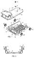
- Fig. 1 shows an optical/electronic module 1 and a supporting structure 10 of an electro-optical device.
- the electro-optical device consists, for example, of a laser gun for reading optical codes.
- the module 1 comprises an optical unit 3 and an electronic unit 40 (shown as a block in broken lines) mounted on a board 2.
- the optical unit 3 comprises a laser (diode) source which emits a laser beam and optical components for focusing and driving the laser beam, which in turn comprise a movable mirror (not shown).
- the optical unit could contain a light source of the LED type and sensors of the CCD and CMOS type.
- the electronic unit comprises electronic components and a printed circuit formed on the board 2 and connected to a cable by means of electrical connections (not shown).
- the board 2 has a hole 5 and two eyelets 4, only one of which can be seen in Fig. 1.
- the hole 5 is located close to one end of the board 2 and the eyelets 4 are spaced from the hole 5 and are located in the vicinity of the optical unit 3 on two longitudinal sides of the board 2.
- Fig. 1 also shows a washer 6 and a screw 7, the function of which will be illustrated further below.
- the supporting structure 10 comprises a support frame 11 and four ring-shaped bearings 12.
- the frame 11 is formed in the manner of a shell and has a bottom wall 13 and side walls 14.
- the wall 13 is provided with a hollow stud 15 designed to penetrate into the hole 5 of the board 2.
- Lugs 16 and 116 are provided at the corners between the wall 13 and the walls 14.
- the walls 14 are provided with resilient tongues 18 (Fig. 2) designed to co-operate with pairs of underlying lugs 116 situated in the vicinity of the optical unit 3, in order to retain the board 2 in the frame 11 in the vertical direction.
- the walls 14 are also provided with teeth 19, only one of which can be seen in Fig.
- Each wall 14 is further provided with a pair of pins 20 for supporting the ring bearings 12.
- the bearings 12 could have other shapes: oval, rectangular, etc.
- the frame 11 is provided with openings 113 which allow the cable with the electrical connections of the printed circuit to pass through.
- the frame 11 is made, for example, of a controlled-deformation material, such as a semi-rigid material, in particular a polymeric material chosen from the group comprising: nylon, acetal resins, polycarbonates and the like. These materials represent the best compromise between elasticity, rigidity and strength.
- a controlled-deformation material such as a semi-rigid material, in particular a polymeric material chosen from the group comprising: nylon, acetal resins, polycarbonates and the like. These materials represent the best compromise between elasticity, rigidity and strength.
- the ring bearings 12 are made of visco-elastic material, for example rubber.
- the frame 11 may be made of a rigid material, such as a metallic material, or a substantially resilient material.
- the bearings 12 are made of a material such as to provide the structure 10 with the desired characteristics of capacity for absorption and dissipation of the impact energy.
- the optical/electronic module 1 is mounted in the frame 11, by splaying the side walls 14 and positioning the board 2 on the lugs 16 so that the stud 15 enters into the hole 5 and the teeth 19 engage inside the eyelets 4.
- the board 2 is retained between the tongues 18 and the pairs of underlying tugs 116.
- the ring bearings 12 are mounted on the pins 20.
- connection provided between the board 2 and the frame 11 by means of the eyelets 4 and the teeth 19, the lugs 16 and 116 and the tongues 18, allow relative movements of the board and the frame and prevent the deformations of the frame from being transmitted to the board.
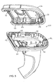
- Fig. 3 shows a casing 25 in the form of a gun, which is designed to contain the group formed by the supporting structure 10 and the optical/electronic module 1.
- the casing may have a banana shape or other shape.
- the casing 25 comprises a base 26 and a cover 27 provided, respectively, with four half-seats 28 and four half-seats 29 for the pins 20 and the bearings 12.
- the half-seats 28 and 29 are formed by means of interstices delimited by wall portions 30 and 31 with semicircular edges.
- the base 26 has three through-holes 32 and the cover 27 has three blind holes 33.
- the holes 32 receive inside them screws, not shown, which are screwed into the holes 33 in order to fix the cover 27 to the base 26.
- the group formed by the structure 10 and the module 1 is mounted inside the cover 27 so that the ring bearings 12 are housed in the half-seats 29. Then the cover 27 is positioned on the base 26 so as to house the bearings 12 in the half-seats 28 and finally the cover 27 is screwed to the base 26.
- the support frame and the bearings may be moulded together and form a single body.
- the external casing and the support frame may be moulded together and connected by means of resilient bridge-pieces.
Landscapes
- Physics & Mathematics (AREA)
- Engineering & Computer Science (AREA)
- Electromagnetism (AREA)
- Artificial Intelligence (AREA)
- Toxicology (AREA)
- General Health & Medical Sciences (AREA)
- Health & Medical Sciences (AREA)
- Computer Vision & Pattern Recognition (AREA)
- General Physics & Mathematics (AREA)
- Theoretical Computer Science (AREA)
- Devices For Indicating Variable Information By Combining Individual Elements (AREA)
- Studio Devices (AREA)
- Mounting Components In General For Electric Apparatus (AREA)
- Facsimile Heads (AREA)
- Optical Head (AREA)
Claims (19)
- Tragbare elektro-optische Einrichtung mit einem optischen/elektronischen Modul (1), einem externen Gehäuse (25), das zum Aufnehmen des Moduls (1) gestaltet ist, und einer Stützstruktur (10), die zwischen dem Modul (1) und dem externen Gehäuse (25) angeordnet ist, wobei die Stützstruktur (10) mit dem externen Gehäuse (25) verbunden ist und einen Rahmen (11) aufweist, wobei die Einrichtung ferner eine Platte (2) umfaßt, die von dem Rahmen (11) gehalten ist, dadurch gekennzeichnet, daß das optische/elektrische Modul (1) auf der Platte (2) montiert ist und daß der Rahmen (11) wenigstens ein Element (19) umfaßt, das dazu gestaltet ist, mit wenigstens einer in der Platte (2) ausgebildeten Öse (4) in Eingriff zu kommen, um die Platte (2) in dem Rahmen (11) in Längsrichtung zu halten.
- Elektro-optische Einrichtung nach Anspruch 1, dadurch gekennzeichnet, daß der Rahmen (11) Haltenasen (16; 116) zum Halten der Platte (2) sowie wenigstens eine nachgiebige Zunge (18) aufweist, die dazu gestaltet ist, mit wenigstens einer Nase (116) zusammenzuwirken, um die Platte (2) in dem Rahmen (11) vertikal zu halten.
- Elektro-optische Einrichtung nach einem der vorangehenden Ansprüche, dadurch ge-kennzeichnet, daß der Rahmen (11) eine Bodenwand (13) und zwei Seitenwände (14) aufweist, wobei das wenigstens eine Element (19) in wenigstens einer der Seitenwände (14) vorgesehen ist.
- Elektro-optische Einrichtung nach einem der vorangehenden Ansprüche, dadurch ge-kennzeichnet, daß die Stützstruktur (10) kontrolliert verformbar ist und Energie infolge von Schlagbeanspruchung aufnehmen kann.
- Elektro-optische Einrichtung nach einem der vorangehenden Ansprüche, dadurch gekennzeichnet, daß das Modul (1) eine optische Einheit (3) und eine elektronische Einheit (40) aufweist, die beide auf der Platte (2) montiert sind.
- Elektro-optische Einrichtung nach einem der vorangehenden Ansprüche, dadurch gekennzeichnet, daß der Rahmen (11) Stifte (20) zur Verbindung mit dem externen Gehäuse (25) aufweist.
- Elektro-optische Einrichtung nach einem der vorangehenden Ansprüche, dadurch gekennzeichnet, daß die Platte (20) wenigstens ein Loch (5) und der Rahmen (11) wenigstens einen hohlen Zapfen (15) aufweist, wobei der Zapfen so gestaltet ist, daß er in das Loch (5) eindringen kann, um an der Platte (2) befestigt zu werden.
- Elektro-optische Einrichtung nach einem der vorangehenden Ansprüche, dadurch gekennzeichnet, daß das wenigstens eine Element in der Form eines Zahns (19) ausgebildet ist.
- Elektro-optische Einrichtung nach einem der vorangehenden Ansprüche, dadurch gekennzeichnet, daß viskoelastische Elemente (12) zwischen dem Stützrahmen (11) und dem externen Gehäuse (25) angeordnet sind.
- Elektro-optische Einrichtung nach Anspruch 9, dadurch gekennzeichnet , daß die viskoelastischen Elemente (12) Gummilager sind.
- Elektro-optische Einrichtung nach den Ansprüchen 6 und 10, dadurch gekennzeichnet, daß die Gummilager (12) ringförmig sind und an den Stiften (20) angebracht sind
- Elektro-optische Einrichtung nach Anspruch 6, dadurch gekennzeichnet, daß das Gehäuse (25) einen Boden (26) und einen Deckel (27) aufweist, wobei der Boden (26) und der Deckel (27) jeweils mit Halb-Sitzen (28, 29) ausgestattet sind, die so gestaltet sind, daß sie die Stifte (20) aufnehmen können.
- Elektro-optische Einrichtung nach den Ansprüchen 10 und 12, dadurch gekennzeichnet, daß die Halb-Sitze (28, 29) so gestaltet sind, daß sie auch die Lager (12) aufnehmen können.
- Elektro-optische Einrichtung nach einem der vorangehenden Ansprüche, dadurch ge-kennzeichnet, daß der Stützrahmen (11) aus einem halbstarren Material hergestellt ist.
- Elektro-optische Einrichtung nach Anspruch 14, dadurch gekennzeichnet, daß das Material Kunststoff ist und aus der folgenden Gruppe ausgewählt ist: Nylon, Azetalharze und Polykarbonate.
- Elektro-optische Einrichtung nach einem der vorangehenden Ansprüche, dadurch gekennzeichnet, daß der Stützrahmen (11) aus einem starren Material hergestellt ist.
- Elektro-optische Einrichtung nach einem der vorangehenden Ansprüche, dadurch gekennzeichnet, daß der Stützrahmen (11) aus einem im wesentlichen nachgiebigen Material hergestellt ist.
- Elektro-optische Einrichtung nach Anspruch 5, dadurch gekennzeichnet, daß die optische Einheit (3) eine Laserquelle umfaßt, die einen Laserstrahl aussendet, sowie optische Komponenten zum Fokussieren und Lenken des Laserstrahls.
- Elektro-optische Einrichtung nach Anspruch 5, dadurch gekennzeichnet, daß die optische Einheit (3) eine Quelle diffusen Lichts und einen Sensor des CCD- oder CMOS-Typs aufweist.
Priority Applications (4)
| Application Number | Priority Date | Filing Date | Title |
|---|---|---|---|
| DE69837662T DE69837662T2 (de) | 1998-10-15 | 1998-10-15 | Tragbare elektro-optische Vorrichtung |
| EP98830611A EP0994436B1 (de) | 1998-10-15 | 1998-10-15 | Tragbare elektro-optische Vorrichtung |
| AT98830611T ATE360857T1 (de) | 1998-10-15 | 1998-10-15 | Tragbare elektro-optische vorrichtung |
| US09/362,988 US6442180B1 (en) | 1998-10-15 | 1999-07-30 | Portable electro-optical device |
Applications Claiming Priority (1)
| Application Number | Priority Date | Filing Date | Title |
|---|---|---|---|
| EP98830611A EP0994436B1 (de) | 1998-10-15 | 1998-10-15 | Tragbare elektro-optische Vorrichtung |
Publications (2)
| Publication Number | Publication Date |
|---|---|
| EP0994436A1 EP0994436A1 (de) | 2000-04-19 |
| EP0994436B1 true EP0994436B1 (de) | 2007-04-25 |
Family
ID=8236833
Family Applications (1)
| Application Number | Title | Priority Date | Filing Date |
|---|---|---|---|
| EP98830611A Expired - Lifetime EP0994436B1 (de) | 1998-10-15 | 1998-10-15 | Tragbare elektro-optische Vorrichtung |
Country Status (4)
| Country | Link |
|---|---|
| US (1) | US6442180B1 (de) |
| EP (1) | EP0994436B1 (de) |
| AT (1) | ATE360857T1 (de) |
| DE (1) | DE69837662T2 (de) |
Families Citing this family (8)
| Publication number | Priority date | Publication date | Assignee | Title |
|---|---|---|---|---|
| DE10106542B4 (de) * | 2001-02-13 | 2004-10-21 | Datasound Gmbh | Lesegerät zur Abtastung eines kodierte Information enthaltenden Datenstreifens |
| US7012216B2 (en) * | 2002-02-08 | 2006-03-14 | Honeywell International | Hand-held laser welding wand having internal coolant and gas delivery conduits |
| US7550693B2 (en) * | 2005-02-04 | 2009-06-23 | Honeywell International Inc. | Hand-held laser welding wand with improved optical assembly serviceability features |
| DE102008009404B4 (de) * | 2008-02-15 | 2013-01-24 | Marson Technology Co., Ltd. | Allseitig strahlender Strichcodeleser |
| JP5809013B2 (ja) * | 2011-10-14 | 2015-11-10 | 株式会社キーエンス | 光学情報読取装置 |
| USD982585S1 (en) | 2013-12-05 | 2023-04-04 | Hand Held Products, Inc. | Indicia scanner |
| USD734339S1 (en) * | 2013-12-05 | 2015-07-14 | Hand Held Products, Inc. | Indicia scanner |
| USD826234S1 (en) | 2016-04-11 | 2018-08-21 | Hand Held Products, Inc. | Indicia scanner |
Family Cites Families (2)
| Publication number | Priority date | Publication date | Assignee | Title |
|---|---|---|---|---|
| US5198651A (en) * | 1991-05-03 | 1993-03-30 | Symbol Technologies, Inc. | Laser diode device incorporating structure with integral scanning motor |
| US5543609A (en) * | 1994-10-28 | 1996-08-06 | Symbol Technologies, Inc. | Arrangement for and method of providing shock protection and vibration isolation for a scan module |
-
1998
- 1998-10-15 EP EP98830611A patent/EP0994436B1/de not_active Expired - Lifetime
- 1998-10-15 AT AT98830611T patent/ATE360857T1/de not_active IP Right Cessation
- 1998-10-15 DE DE69837662T patent/DE69837662T2/de not_active Expired - Lifetime
-
1999
- 1999-07-30 US US09/362,988 patent/US6442180B1/en not_active Expired - Lifetime
Also Published As
| Publication number | Publication date |
|---|---|
| DE69837662D1 (de) | 2007-06-06 |
| EP0994436A1 (de) | 2000-04-19 |
| US6442180B1 (en) | 2002-08-27 |
| ATE360857T1 (de) | 2007-05-15 |
| DE69837662T2 (de) | 2007-12-27 |
Similar Documents
| Publication | Publication Date | Title |
|---|---|---|
| US5440111A (en) | Optical system for scanning and reading barcodes with manually controlled scan beam length | |
| US6239986B1 (en) | Housing body of electronic equipment | |
| ES2087857T3 (es) | Modulo explorador en miniatura para lectores de codigos de barras y similares. | |
| US6442180B1 (en) | Portable electro-optical device | |
| DE69232678D1 (de) | Ring scanner | |
| EP1632882A3 (de) | Strichcodeleser mit auf einer Leiterplatte montierbarem integriertem Scan-Komponentenmodul | |
| EP0698854A2 (de) | Tragbarer Abtaster | |
| EP0973119A3 (de) | Optischer Leser mit neigbarem Tisch auf dem eine optische Einheit befestigt ist | |
| US20060068624A1 (en) | Light grid with housing | |
| US10039196B2 (en) | Portable device | |
| KR950006024Y1 (ko) | 싱글렌즈 리플렉스 카메라 | |
| US10384541B2 (en) | Laser radar module and robot | |
| EP0905642A2 (de) | Lichtquellenmodul für eine Abtastanordnung und eine Abtastanordnung mit diesem Modul | |
| ES2078569T3 (es) | Procedimiento para el equipamiento de contadores electricos con un respectivo modulo externo, y pieza intermedia para la realizacion del procedimiento. | |
| US20220244623A1 (en) | Camera support structure and head-mounted display | |
| CN210166550U (zh) | 镜头模组 | |
| EP3477936B1 (de) | Bildgebungsvorrichtung | |
| US12248627B2 (en) | Electronic module for a wearable sensor system as well as wearable sensor system | |
| EP0410565A2 (de) | Stromversorgungsgerät | |
| US5726813A (en) | Optical apparatus with replacement semiconductor laser | |
| JP2005339830A (ja) | 電気部品用ソケット装置 | |
| EP3454540A1 (de) | Bildherstellungsvorrichtung | |
| KR20220127960A (ko) | 인쇄회로기판의 다층 실장 가능한 카메라모듈 | |
| JP2008277141A (ja) | コネクタ用部品、コネクタシステム、および電子機器 | |
| US11546517B2 (en) | Drive device including magnet units arranged in Halbach array, shake correction device, and image capturing apparatus |
Legal Events
| Date | Code | Title | Description |
|---|---|---|---|
| PUAI | Public reference made under article 153(3) epc to a published international application that has entered the european phase |
Free format text: ORIGINAL CODE: 0009012 |
|
| AK | Designated contracting states |
Kind code of ref document: A1 Designated state(s): AT BE CH DE DK ES FR GB IT LI NL PT SE |
|
| AX | Request for extension of the european patent |
Free format text: AL;LT;LV;MK;RO;SI |
|
| 17P | Request for examination filed |
Effective date: 20000325 |
|
| 17Q | First examination report despatched |
Effective date: 20000628 |
|
| AKX | Designation fees paid |
Free format text: AT BE CH DE DK ES FR GB IT LI NL PT SE |
|
| GRAP | Despatch of communication of intention to grant a patent |
Free format text: ORIGINAL CODE: EPIDOSNIGR1 |
|
| GRAS | Grant fee paid |
Free format text: ORIGINAL CODE: EPIDOSNIGR3 |
|
| GRAA | (expected) grant |
Free format text: ORIGINAL CODE: 0009210 |
|
| AK | Designated contracting states |
Kind code of ref document: B1 Designated state(s): AT BE CH DE DK ES FR GB IT LI NL PT SE |
|
| PG25 | Lapsed in a contracting state [announced via postgrant information from national office to epo] |
Ref country code: LI Free format text: LAPSE BECAUSE OF FAILURE TO SUBMIT A TRANSLATION OF THE DESCRIPTION OR TO PAY THE FEE WITHIN THE PRESCRIBED TIME-LIMIT Effective date: 20070425 Ref country code: CH Free format text: LAPSE BECAUSE OF FAILURE TO SUBMIT A TRANSLATION OF THE DESCRIPTION OR TO PAY THE FEE WITHIN THE PRESCRIBED TIME-LIMIT Effective date: 20070425 |
|
| REG | Reference to a national code |
Ref country code: GB Ref legal event code: FG4D |
|
| REG | Reference to a national code |
Ref country code: CH Ref legal event code: EP |
|
| REF | Corresponds to: |
Ref document number: 69837662 Country of ref document: DE Date of ref document: 20070606 Kind code of ref document: P |
|
| PG25 | Lapsed in a contracting state [announced via postgrant information from national office to epo] |
Ref country code: SE Free format text: LAPSE BECAUSE OF FAILURE TO SUBMIT A TRANSLATION OF THE DESCRIPTION OR TO PAY THE FEE WITHIN THE PRESCRIBED TIME-LIMIT Effective date: 20070725 |
|
| PG25 | Lapsed in a contracting state [announced via postgrant information from national office to epo] |
Ref country code: ES Free format text: LAPSE BECAUSE OF FAILURE TO SUBMIT A TRANSLATION OF THE DESCRIPTION OR TO PAY THE FEE WITHIN THE PRESCRIBED TIME-LIMIT Effective date: 20070805 |
|
| PG25 | Lapsed in a contracting state [announced via postgrant information from national office to epo] |
Ref country code: PT Free format text: LAPSE BECAUSE OF FAILURE TO SUBMIT A TRANSLATION OF THE DESCRIPTION OR TO PAY THE FEE WITHIN THE PRESCRIBED TIME-LIMIT Effective date: 20070925 |
|
| RAP2 | Party data changed (patent owner data changed or rights of a patent transferred) |
Owner name: DATALOGIC SCANNING GROUP S.R.L. |
|
| REG | Reference to a national code |
Ref country code: CH Ref legal event code: PL |
|
| NLV1 | Nl: lapsed or annulled due to failure to fulfill the requirements of art. 29p and 29m of the patents act | ||
| PG25 | Lapsed in a contracting state [announced via postgrant information from national office to epo] |
Ref country code: AT Free format text: LAPSE BECAUSE OF FAILURE TO SUBMIT A TRANSLATION OF THE DESCRIPTION OR TO PAY THE FEE WITHIN THE PRESCRIBED TIME-LIMIT Effective date: 20070425 |
|
| EN | Fr: translation not filed | ||
| PG25 | Lapsed in a contracting state [announced via postgrant information from national office to epo] |
Ref country code: BE Free format text: LAPSE BECAUSE OF FAILURE TO SUBMIT A TRANSLATION OF THE DESCRIPTION OR TO PAY THE FEE WITHIN THE PRESCRIBED TIME-LIMIT Effective date: 20070425 |
|
| PG25 | Lapsed in a contracting state [announced via postgrant information from national office to epo] |
Ref country code: NL Free format text: LAPSE BECAUSE OF FAILURE TO SUBMIT A TRANSLATION OF THE DESCRIPTION OR TO PAY THE FEE WITHIN THE PRESCRIBED TIME-LIMIT Effective date: 20070425 Ref country code: DK Free format text: LAPSE BECAUSE OF FAILURE TO SUBMIT A TRANSLATION OF THE DESCRIPTION OR TO PAY THE FEE WITHIN THE PRESCRIBED TIME-LIMIT Effective date: 20070425 |
|
| PLBE | No opposition filed within time limit |
Free format text: ORIGINAL CODE: 0009261 |
|
| STAA | Information on the status of an ep patent application or granted ep patent |
Free format text: STATUS: NO OPPOSITION FILED WITHIN TIME LIMIT |
|
| 26N | No opposition filed |
Effective date: 20080128 |
|
| PG25 | Lapsed in a contracting state [announced via postgrant information from national office to epo] |
Ref country code: IT Free format text: LAPSE BECAUSE OF FAILURE TO SUBMIT A TRANSLATION OF THE DESCRIPTION OR TO PAY THE FEE WITHIN THE PRESCRIBED TIME-LIMIT Effective date: 20070425 Ref country code: FR Free format text: LAPSE BECAUSE OF FAILURE TO SUBMIT A TRANSLATION OF THE DESCRIPTION OR TO PAY THE FEE WITHIN THE PRESCRIBED TIME-LIMIT Effective date: 20071221 |
|
| PG25 | Lapsed in a contracting state [announced via postgrant information from national office to epo] |
Ref country code: FR Free format text: LAPSE BECAUSE OF FAILURE TO SUBMIT A TRANSLATION OF THE DESCRIPTION OR TO PAY THE FEE WITHIN THE PRESCRIBED TIME-LIMIT Effective date: 20070425 |
|
| PGFP | Annual fee paid to national office [announced via postgrant information from national office to epo] |
Ref country code: DE Payment date: 20151022 Year of fee payment: 18 Ref country code: GB Payment date: 20151021 Year of fee payment: 18 |
|
| REG | Reference to a national code |
Ref country code: DE Ref legal event code: R119 Ref document number: 69837662 Country of ref document: DE |
|
| GBPC | Gb: european patent ceased through non-payment of renewal fee |
Effective date: 20161015 |
|
| PG25 | Lapsed in a contracting state [announced via postgrant information from national office to epo] |
Ref country code: DE Free format text: LAPSE BECAUSE OF NON-PAYMENT OF DUE FEES Effective date: 20170503 Ref country code: GB Free format text: LAPSE BECAUSE OF NON-PAYMENT OF DUE FEES Effective date: 20161015 |