EP0905642A2 - Lichtquellenmodul für eine Abtastanordnung und eine Abtastanordnung mit diesem Modul - Google Patents
Lichtquellenmodul für eine Abtastanordnung und eine Abtastanordnung mit diesem Modul Download PDFInfo
- Publication number
- EP0905642A2 EP0905642A2 EP98304263A EP98304263A EP0905642A2 EP 0905642 A2 EP0905642 A2 EP 0905642A2 EP 98304263 A EP98304263 A EP 98304263A EP 98304263 A EP98304263 A EP 98304263A EP 0905642 A2 EP0905642 A2 EP 0905642A2
- Authority
- EP
- European Patent Office
- Prior art keywords
- housing
- scanning
- light source
- aperture
- laser
- Prior art date
- Legal status (The legal status is an assumption and is not a legal conclusion. Google has not performed a legal analysis and makes no representation as to the accuracy of the status listed.)
- Granted
Links
Images










Classifications
-
- G—PHYSICS
- G06—COMPUTING OR CALCULATING; COUNTING
- G06K—GRAPHICAL DATA READING; PRESENTATION OF DATA; RECORD CARRIERS; HANDLING RECORD CARRIERS
- G06K7/00—Methods or arrangements for sensing record carriers, e.g. for reading patterns
- G06K7/10—Methods or arrangements for sensing record carriers, e.g. for reading patterns by electromagnetic radiation, e.g. optical sensing; by corpuscular radiation
- G06K7/10544—Methods or arrangements for sensing record carriers, e.g. for reading patterns by electromagnetic radiation, e.g. optical sensing; by corpuscular radiation by scanning of the records by radiation in the optical part of the electromagnetic spectrum
- G06K7/10554—Moving beam scanning
- G06K7/10564—Light sources
Definitions
- the invention relates to a light source module for a scanning apparatus such as a bar code reader, and to a scanning apparatus with the light source module.
- POS systems point-of-sale systems
- a bar code reader reads a bar code provided on an article.
- check-out work is carried out only by scanning a beam emitted from a bar code reader.
- the work of operator is reduced by using a bar code reader.
- a bar code reader generally includes a light source for emitting a beam, an arrangement for generating a scanning beam by reflecting the beam from the light source, such as a rotating polygon mirror, a plurality of mirrors for reflecting the scanning beam and for dividing the scanning beam to provide a set of scanning lines outside of the bar code reader.
- the return beams reflected by a bar code on an article are condensed by a concave mirror or a condenser lens onto a light receiving device, such as a photodiode which generates an electrical signal corresponding to the return beams received by the light receiving device.
- These elements are sealingly contained within a housing to provide an optical unit.
- Such an apparatus for reading a bar code is a kind of a scanner apparatus, similar to a scanner device in a laser printer or a copy machine, and is often referred to a POS scanner or a bar code scanner.
- a laser diode is often used as a light source because of its compactness, low power consumption, and cost while a gas laser beam (for example, He-Ne laser beam) was originally used.
- a laser diode has a problem that its life is shorter than a gas laser so that a bar code reader with a laser diode must be designed and used while considering replacement of the light source. Further, there is a problem that static electricity may damage a semiconductor laser.
- a light source is provided by a VLD (Visible Laser Diode) module which includes a laser beam source, a lens and an aperture for shaping a beam.
- VLD Vehicle Laser Diode
- the VLD module When replacing a laser diode, the VLD module is replaced with the laser diode.
- the VLD module is contained within the housing of the optical unit.
- the housing of the optical unit must be opened to replace the VLD module. This work must be carried out in a clean room to prevent dust, which may harmfully effect-the optical characteristics of the scanner, from entering the optical unit.
- the bar code reader to be mended cannot be used during the replacement of the VLD module.
- a light source module or a VLD module for a scanner apparatus, such as a bar code reader, or a scanning device in a laser printer or a copy machine, which is improved so that the light source module can be replaced, without dust entering the optical unit of the scanner apparatus, wherever the scanner apparatus is used.
- a scanner apparatus such as a bar code reader, or a scanning device in a laser printer or a copy machine, which includes the light source module.
- a light source module which has a laser diode and a circuit board.
- the circuit board includes the laser diode, a driver circuit for the laser diode, and a connector for receiving a power supply for driving the laser diode from an electric power source.
- a lens and an aperture shapes the laser beam emitted by the laser diode.
- a housing made of electrically insulating material contains the lens, the aperture and the circuit board except for a portion of the circuit board where the connector is mounted.
- Such a light source module may be replaced more easily. Moreover, the possibility of damage to the laser diode by static electricity may be removed or reduced, since the operator can replace the light source module without touching the laser diode.
- a scanning apparatus which comprises:
- a scanner for emitting a scanning beam comprises:
- the optical unit preferably includes a scanning mirror for producing a scanning beam, a plurality of mirrors for reflecting the scanning beam and for dividing the scanning beam into first and second sets of scanning beam segments, an optical receiver element for receiving the return beam reflected by a bar code to produce an electrical signal responsive to the return beam, and a housing for enclosing the scanning mirror, the plurality of mirrors, and the optical receiver element, the housing including an aperture, and first and second openings through which the first and second sets of scanning beam segments propagate outside of the housing to provide fist and second sets of scanning lines outside of the scanner.
- the light source is secured to the exterior of the housing to direct the light beam to the scanning mirror through the aperture provided in the housing.
- a bar code scanner for reading a bar code comprises:
- a bar code scanner for reading a bar code comprises:
- an embodiment of the present invention is applied to a bar code reader.
- an embodiment of the present invention can also be applied, for example, to a scanner device in a laser printer or a copy machine, etc, .
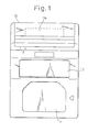
- Figure 1 is a front view of a bar code scanner incorporating an embodiment of the present invention.
- Figure 2 is a side section showing the internal arrangement of the bar code scanner.
- the bar code scanner is of an upright type and is mounted to a top surface 10 of a table such as a cashier counter.
- the housing of the scanner includes first and second openings 11 and 12 through which first and second scanning beams propagate outside of the housing, respectively.
- the first opening is perpendicular to the top surface 10.
- the first scanning beam horizontally propagates through the first opening 11 while the second scanning beam propagates obliquely downwardly through the second opening 12.
- the first and second beams intersect in front of the first opening 11.
- a bar code (not shown) on an article (not shown) is irradiated by at least one of the first and second beams when the bar code passes the reading area where the first and second beams intersect in front of the bar code reader.
- a bar code reader with a single opening cannot read a bar code if an operator does not orient the bar code to the window accurately.
- the provision of two sets of openings and beams enables the scanner to read the bar code if an operator does not orient the bar code to the first or second opening accurately.
- the display 13 includes first and second indicators 13a and 13b, respectively.
- the first and second indicators 13a and 13b are oriented to the operator of the scanner and the customer.
- the first and second indicators 13a and 13b may indicate the same information.
- the scanner further includes an optical unit 14 and a VLD (Visible Laser Diode) module 15, as a light source module.
- VLD Vehicle Laser Diode
- the VLD module 15 is mounted outside of the optical unit 14 by screws 16 (only one of which is shown in the drawings).
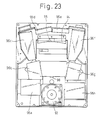
- a polygon mirror 93 within the optical unit 14, a polygon mirror 93, a plurality of mirrors 96a to 96h for providing a set of scanning lines outside of the scanner by reflecting the scanning beam from the polygon mirror 93, and a concave mirror 94 for condensing the reflected beam from the bar code to an optical receiver 98 such as a photodiode are provided.
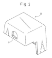
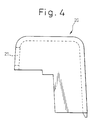
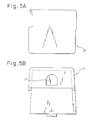
- the VLD module 15 includes a housing portion 20 shown in Figures 3 to 5B, and a cover 30 shown in Figures 6A to 8, both of which are made of molded resin.
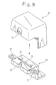
- the housing portion 20 includes an aperture 21 through which a laser beam is emitted from a laser diode contained in the housing 20 and 30 to the polygon mirror 93 as described hereinafter. It should be noted that although the housing portion 20 is shown in Figures 3, 4, 5 and 9, so that the aperture 21 is laterally oriented, the VLD module 15 attached to the optical unit 14 so that the aperture 21 is oriented to the bottom of the unit 14 as shown in Figure 20. In this specification, “top” and “bottom” are defined as the orientation shown in the drawings.
- the cover 30 comprises a base 31, and a pair of mounting members 32 extending from the sides of the base 31.
- the base 31 includes a ridged portion 33 on the base 31, a pair of through holes 34, a cutout 36 for positioning the VLD module to the optical unit 14, and a hook 35 adjacent to the cutout 36.
- Each of the mounting members 32 includes a through hole 32a into which a screw 16 ( Figure 2) is inserted to secure the VLD module to the optical unit 14.
- the cover 30 is connected to the housing portion 20 to close the opening of the housing portion 20, as shown in Figure 9, to provide a housing of the VLD module 15.
- the mount 40 for securing the laser beam source inside of the housing of the VLD module.
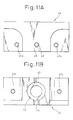
- the mount 40 includes two pairs of threaded holes 41a and 41b and a recess 45 adapted to fit the ridged portion 33 on the top surface of the base 31 of the cover 30, and may be made of die cast aluminum.
- the threaded holes 41a receive screws 71 ( Figure 18) which are inserted into the through holes 34 of the cover 30 to secure the mount 40 to the base 31 of the cover 30.
- the threaded holes 41b receive screws 63 ( Figures 16A and 16B) to secure a printed circuit board as mentioned hereinafter.
- the mount 40 further includes a bore 42 into which a lens holder 50 (Figures 13 to 15) is fitted, and a threaded hole 43 into which a screw 64 ( Figures 16A and 16C) is threaded to lock the lens holder 50.
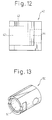
- the lens holder 50 is shaped in the form of a cylinder which includes a bore 51 and a flattened portion 52 to which the tip of the screw 64 abuts to lock the holder 50.
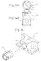
- the lens holder 50 holds an aperture plate 53 which includes an aperture 53a and a lens 54 which is fixed to the inside of the bore 51 ( Figures 14A and 14B).
- the aperture 53a shapes the beam to provide a desirable beam section.
- the configuration of the aperture 53a can be selected according to the desirable section of the laser beam while the aperture 53a has a rectangular configuration in the embodiment shown in Figures 14A and 14B.
- the lens 54 adjusts the focal point of the beam.
- the aperture plate 53 and the lens 54 adjust the diameter of the laser beam.
- the lens holder 50 is slidably fitted into the bore 42 of the mount 40 as shown Figure 15.
- the movement of the lens holder 50 within the bore 42 in the longitudinal direction shown by an arrow A in Figure 15 changes the position of the focal point of the laser beam within the reading area in front of the bar code reader.
- Changing the position of the focal point adjusts the diameter of the laser beam within the reading area.
- the adjustment of the lens beam diameter is a critical issue since the diameter is the factor which defines the capability of reading a bar code (resolution for reading). The smaller the diameter, within an appropriate range, the narrower the bars of a bar code which can be read.
- the VLD module 15 comprises the lens holder as means for shaping the laser beam separately from the mount 40, which facilitates the adjustment of the diameter of the laser beam.
- a circuit board 61 is attached to the mount 40 by the pair of screws 63 threaded into the holes 41b of the mount 40.
- the circuit board 61 includes a laser diode 62 secured to the circuit board 61, and a driver circuit (not shown) for driving the diode laser 62.
- the circuit board 61 is attached to the mount 40 so that the optical axis of the beam from the laser diode 62 is aligned with that of the lens holder 50, in particular, that of the aperture 53a and the lens 54 held by the lens holder 50.
- a laser diode has a characteristic that the power of the emitted beam is not uniform from one to the other.
- a variable resistor 65 is provided for adjustment of the beam power emitted from the laser diode 62 so that the fluctuation in capability of reading between the scanners decreases.
- a connector 66 for connecting the laser diode 62 to a power source, is also provided on the circuit board 61.
- the circuit board 61 except for the connector 66, the mount 40 and the lens holder 50 are contained within the housing 20 and 30 to provide the VLD module 15.
- the mount 40 is disposed on the cover 30 in place by the fitting between the recess 45 ( Figure 10) provided in the mount 40 and the ridged portion 33 on the top surface of the base 31 of the cover 30.
- the mount 40 is secured to the cover 30 by screws 71 which are inserted into the through holes 34 of the cover 30 and threaded into the threaded holes 41a of the mount 40.
- the laser diode 62 is disposed relative to the mount 40 and the lens holder 50.
- the laser diode 62 is contained within the housing 20 and 30 which are made of molded resin, such as ABS (acrylonitrile-butadien-styrene) resin.
- ABS acrylonitrile-butadien-styrene
- the lens holder is also contained within the housing 20 and 30 to reduce an external force on the lens holder.
- This feature of the invention is advantageous in that the lens holder does not move during the replacement of the VLD module 15, which prevents a change in the diameter of the laser beam.
- the optical unit 14 includes a housing portion 14a and cover 14b which are connected to each other to provide a housing of the optical unil 14.
- the-housing portion 14a and the cover 14b are sealingly connected at line 83 so that dust or small particles cannot enter therethrough.
- the cover 14b includes first and second openings 11 and 12 which are sealingly and transparently covered by first and second glass plates 81 and 82, respectively.
- first and second scanning beams propagate through the first and second glass plates 81 and 82, respectively.
- the VLD module 15 is secured to the top of the housing portion 14a of the optical unit 14 by screws 16 ( Figures 19 and 20).
- the damper 17 between the VLD module 15 and optical unit 14 ( Figure 20) prevents dust from entering the optical unit 14 through a possible gap therebetween, and prevents vibration of the scanner from being transmitted to the VLD module 15.
- a horizontal protrusion 91 for positioning the VLD module 15.
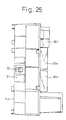
- an aperture 92 ( Figures 25 and 26) is provided through the outer wall to open into inside of the housing of the optical unit 14.
- An aperture 95 ( Figure 23) is provided through the condensing concave mirror 94 at the center thereof so that the apertures 92 and 95 provide a passage through which the laser beam propagates from the VLD module 15, which is mounted to the housing portion 14a of the optical unit 14, to the polygon mirror 95.
- the aperture 92 is closed by a glass plate 92a ( Figure 24) which is attached to the inner surface of the housing portion 14a.
- the glass plate 92a is obliquely provided relative to the optical axis of the VLD module 15 to prevent total reflection of the laser beam at the glass plate.
- the aperture 92 may not be closed by the glass plate 92a since the damper 71 prevents dust from entering.
- the laser beam entering the optical unit 14 through the apertures 92 and 95 is reflected by the rotating polygon mirror 93, which includes four mirrors in this embodiment, so that the beam scans the mirrors 96a to 96h.
- the scanning beam from the polygon mirror 93 is divided into a set of scanning beam segments when the beam scans the respective mirrors 96a to 96b so that a set of scanning lines are provided outside of the scanner.
- the mirrors 96a to 96h are referred to as beam dividing mirrors in this specification.
- the dividing mirrors 96a to 96h are oriented to produce first and second sets of scanning lines outside of the scanner through the first and second openings 11 and 12, respectively. Another set of beam dividing mirrors may be provided and attached to the cover 14b.
- the scanning beam is diffusely reflected by a bar code. A portion of each reflected beam returns along the coincident light path of the emitted beam. Thus, the return beam is reflected by the polygon mirror 93 toward the aperture 95 which is provided through the concave mirror 94 for condensing the return beam onto the optical sensor 98.
- the optical sensor 98 generates an electrical signal corresponding to the return beam to a signal processor (not shown).
- the laser diode 62 is directly oriented to the polygon mirror 93 without a additional small mirror which is often provided around the concave mirror in some previously-proposed scanners.
- positioning between the laser source 63, additional mirror, and the polygon mirror 93 is not necessary.
- the aperture 92 is obliquely formed in the housing portion 14a as shown in Figure 24 so that the laser beam runs to the polygon mirror 93 along a line which slants from vertical line.
- the polygon mirror 93 reflects the beam vertically toward the dividing mirrors 96a to 96h.
- Figures 25 and 26 show a top and sectional views of the housing portion 14a, respectively, to which the VLD module 15 is mounted.
- the aperture 92 is provided substantially at the center of the housing portion 14a.
- the housing portion 14a has a recess 103 on the outside surface of the back wall thereof.
- the recess 103 accommodates a control circuit board (not shown) for controlling the operation of the scanner.
- the circuit board 61 of the VLD module 15 is connected to the control circuit board by a flat cable 101.
- Figures 28 and 29 are a side and top views of the housing portion 14a.
- the control circuit board and the VLD module cannot be directly connected to each other since the surface including the recess 103 to which the control circuit board is mounted and the surface to which the VLD module 15 is mounted are substantially perpendicular to each other as shown in Figures 28 and 29. Therefore, the control circuit board and the VLD module 15, are connected through the flat cable 101.
- the provision of the connector 66 outside of the housing 20 and 30 facilitates the attachment of the flat cable 101 to the connector 66.
- one end of the flat cable 101 is connected to the connector 66 and the other end 102 is connected to the control circuit board.
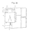
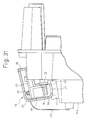
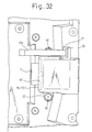
- FIGs 30 to 32 show enlarged details of the VLD module 15 mounted to the housing portion 14a.
- the VLD module 15 emits the laser beam as shown by an arrow B as shown Figure 31.
- the damper 17 includes a passage 17a along which allow B which allows the laser beam propagates through the damper into the aperture 92.
- the VLD module is provided within the optical unit 14.
- the VLD module must be formed as small as possible.
- the VLD module includes a laser diode only included in a housing, and necessary electrical circuits, such as an electric voltage transformer, a driver circuit and an output control circuit, are provided outside of the VLD module.
- FIGs 33 and 34 show block diagrams of electrical circuitry for a VLD module embodying the present invention and a previous proposal, respectively.
- electric power is supplied to the laser diode (VLD) from a power source 110, such as a commercial electric line, through a transformer circuit, a driver circuit and output control circuit for the laser diode which are provided on a board 120 separate from a VLD module 122 as shown in Figure 34.
- a driver circuit and a output control circuit are provided on an additional board 114, which also corresponds to the circuit board 61, separate from a board for a transformer circuit 112 ( Figure 33).
- the circuit board 61 is contained within the housing 20 and 30 to provide the VLD module 15.
- the power of the beam emitted from a laser diode relative to the input electric current is not uniform from one laser diode to another.
- the driver and output control circuits are separately provided from the VLD module. Therefore, the output of the laser diode must be adjusted through the adjustment of the input electric current by the variable resistor 65 and must be carried out wherever the VLD module 15 is replaced.
- the VLD module 15 includes the driver and output control circuits in the VLD module 15.
Landscapes
- Physics & Mathematics (AREA)
- Electromagnetism (AREA)
- Engineering & Computer Science (AREA)
- Health & Medical Sciences (AREA)
- General Health & Medical Sciences (AREA)
- Toxicology (AREA)
- Artificial Intelligence (AREA)
- Computer Vision & Pattern Recognition (AREA)
- General Physics & Mathematics (AREA)
- Theoretical Computer Science (AREA)
- Mechanical Optical Scanning Systems (AREA)
- Semiconductor Lasers (AREA)
Applications Claiming Priority (3)
| Application Number | Priority Date | Filing Date | Title |
|---|---|---|---|
| JP9264741A JPH11112097A (ja) | 1997-09-30 | 1997-09-30 | 光源モジュールおよび光走査装置 |
| JP264741/97 | 1997-09-30 | ||
| JP26474197 | 1997-09-30 |
Publications (3)
| Publication Number | Publication Date |
|---|---|
| EP0905642A2 true EP0905642A2 (de) | 1999-03-31 |
| EP0905642A3 EP0905642A3 (de) | 2002-01-02 |
| EP0905642B1 EP0905642B1 (de) | 2006-08-02 |
Family
ID=17407539
Family Applications (1)
| Application Number | Title | Priority Date | Filing Date |
|---|---|---|---|
| EP98304263A Expired - Lifetime EP0905642B1 (de) | 1997-09-30 | 1998-05-29 | Lichtquellenmodul für eine Abtastanordnung und eine Abtastanordnung mit diesem Modul |
Country Status (5)
| Country | Link |
|---|---|
| US (2) | US6283373B1 (de) |
| EP (1) | EP0905642B1 (de) |
| JP (1) | JPH11112097A (de) |
| CN (3) | CN1305294C (de) |
| DE (1) | DE69835405T2 (de) |
Families Citing this family (12)
| Publication number | Priority date | Publication date | Assignee | Title |
|---|---|---|---|---|
| JPH11112097A (ja) * | 1997-09-30 | 1999-04-23 | Fujitsu Ltd | 光源モジュールおよび光走査装置 |
| JP2003174293A (ja) * | 2001-12-04 | 2003-06-20 | Pentax Corp | ガイド部材及び発光素子の基板取付方法 |
| JP2007223301A (ja) * | 2006-01-27 | 2007-09-06 | Ricoh Co Ltd | 画像形成装置 |
| JP4884035B2 (ja) * | 2006-03-08 | 2012-02-22 | 株式会社リコー | 光書き込み装置 |
| US8269111B2 (en) * | 2006-10-25 | 2012-09-18 | George Scifo | Scrunch-it earpiece/wire organizer and method of using same |
| US20100044435A1 (en) * | 2008-08-22 | 2010-02-25 | Sven Ahlberg | Handheld scanning device with triple data acquisition functionality |
| WO2013140308A1 (en) * | 2012-03-22 | 2013-09-26 | Primesense Ltd. | Diffraction-based sensing of mirror position |
| CN103279729B (zh) * | 2013-05-21 | 2016-01-20 | 苏州斯普锐智能系统有限公司 | 一种具有遮光零件的条码扫描器 |
| EP3089417A1 (de) | 2015-04-30 | 2016-11-02 | Thomson Licensing | Vorrichtung und verfahren zur reduzierung der spitzen-durchschnitts-rate in einem signal |
| US10012831B2 (en) | 2015-08-03 | 2018-07-03 | Apple Inc. | Optical monitoring of scan parameters |
| US11681019B2 (en) | 2019-09-18 | 2023-06-20 | Apple Inc. | Optical module with stray light baffle |
| US11506762B1 (en) | 2019-09-24 | 2022-11-22 | Apple Inc. | Optical module comprising an optical waveguide with reference light path |
Family Cites Families (24)
| Publication number | Priority date | Publication date | Assignee | Title |
|---|---|---|---|---|
| US726813A (en) * | 1903-02-14 | 1903-04-28 | Francois X Brunelle | Automatic boiler-feed controller. |
| US5218188A (en) * | 1989-10-24 | 1993-06-08 | Norand Corporation | Compact hand-held RF data terminal |
| US5202817A (en) * | 1989-06-07 | 1993-04-13 | Norand Corporation | Hand-held data capture system with interchangeable modules |
| US4926433A (en) | 1987-10-19 | 1990-05-15 | Ricoh Company, Ltd. | Semiconductor laser unit |
| US5254844A (en) * | 1988-05-11 | 1993-10-19 | Symbol Technologies, Inc. | Mirrorless scanners with movable laser, optical and sensor components |
| US5015831A (en) * | 1988-11-07 | 1991-05-14 | Photographic Sciences Corporation | Scan modules for bar code readers and the like in which scan elements are flexurally supported |
| US5872354A (en) * | 1989-01-31 | 1999-02-16 | Norand Corporation | Hand-held data capture system with interchangable modules including autofocusing data file reader using the slope of the image signal to determine focus |
| US5589679A (en) * | 1989-10-30 | 1996-12-31 | Symbol Technologies, Inc. | Parallelepiped-shaped optical scanning module |
| US5115120A (en) * | 1990-06-26 | 1992-05-19 | Photographic Sciences Corporation | Scan modules for bar code readers and in which scan elements are flexurally supported |
| US5392150A (en) * | 1991-05-15 | 1995-02-21 | Nippondenso Co., Ltd. | Optical information reading device |
| EP0533110B1 (de) * | 1991-09-19 | 1995-03-15 | Eastman Kodak Company | Laserdiode mit Kartenrandverbinder |
| JPH0645706A (ja) | 1992-07-24 | 1994-02-18 | Nec Corp | 半導体レーザモジュール |
| US5629510A (en) * | 1992-12-04 | 1997-05-13 | Psc Inc. | Bar code scanning and reading apparatus with an oscillating scanning engine |
| JPH07134259A (ja) | 1993-11-12 | 1995-05-23 | Nec Corp | レーザ走査光学装置 |
| JPH07254160A (ja) * | 1994-03-14 | 1995-10-03 | Fujitsu Ltd | 光学装置及び光源ユニット |
| NL9401302A (nl) * | 1994-08-11 | 1996-03-01 | Scantech Bv | Barcode scanner. |
| JPH08211317A (ja) * | 1995-02-06 | 1996-08-20 | Canon Inc | 光偏向走査装置 |
| JPH08236873A (ja) | 1995-02-28 | 1996-09-13 | Canon Inc | 光源装置 |
| JPH08248285A (ja) | 1995-03-13 | 1996-09-27 | Nec Corp | 光源装置 |
| JP3441580B2 (ja) * | 1995-12-14 | 2003-09-02 | 富士通株式会社 | 読取装置 |
| US5920861A (en) * | 1997-02-25 | 1999-07-06 | Intertrust Technologies Corp. | Techniques for defining using and manipulating rights management data structures |
| US5920061A (en) * | 1997-05-29 | 1999-07-06 | Metanetics Corporation | Portable data collection device including imaging assembly with modular high density dataform reader assembly |
| JPH11112097A (ja) * | 1997-09-30 | 1999-04-23 | Fujitsu Ltd | 光源モジュールおよび光走査装置 |
| CN2356314Y (zh) * | 1998-12-27 | 1999-12-29 | 浙江大学现代光学仪器研究所 | 激光扫描力显微镜 |
-
1997
- 1997-09-30 JP JP9264741A patent/JPH11112097A/ja active Pending
-
1998
- 1998-05-28 US US09/084,954 patent/US6283373B1/en not_active Expired - Lifetime
- 1998-05-29 DE DE69835405T patent/DE69835405T2/de not_active Expired - Lifetime
- 1998-05-29 EP EP98304263A patent/EP0905642B1/de not_active Expired - Lifetime
- 1998-06-19 CN CNB03159722XA patent/CN1305294C/zh not_active Expired - Fee Related
- 1998-06-19 CN CNB98114943XA patent/CN1254947C/zh not_active Expired - Fee Related
- 1998-06-19 CN CNB2006101007145A patent/CN100440244C/zh not_active Expired - Fee Related
-
2001
- 2001-05-15 US US09/854,689 patent/US6840452B2/en not_active Expired - Fee Related
Also Published As
| Publication number | Publication date |
|---|---|
| DE69835405T2 (de) | 2006-12-21 |
| CN100440244C (zh) | 2008-12-03 |
| CN1881233A (zh) | 2006-12-20 |
| EP0905642A3 (de) | 2002-01-02 |
| JPH11112097A (ja) | 1999-04-23 |
| US6840452B2 (en) | 2005-01-11 |
| CN1305294C (zh) | 2007-03-14 |
| US6283373B1 (en) | 2001-09-04 |
| EP0905642B1 (de) | 2006-08-02 |
| CN1213244A (zh) | 1999-04-07 |
| DE69835405D1 (de) | 2006-09-14 |
| CN1509062A (zh) | 2004-06-30 |
| US20010023894A1 (en) | 2001-09-27 |
| CN1254947C (zh) | 2006-05-03 |
Similar Documents
| Publication | Publication Date | Title |
|---|---|---|
| EP0085804B1 (de) | Schmaler, mit Einzel- und Doppelfenstern versehener, tragbarer Laserabtastkopf zum Lesen von Strichkodensymbolen | |
| US5015831A (en) | Scan modules for bar code readers and the like in which scan elements are flexurally supported | |
| EP0653723B1 (de) | Abtastelement mit Stosschutz | |
| US5396055A (en) | Hand held bar code reader with keyboard, display and processor | |
| EP0905642B1 (de) | Lichtquellenmodul für eine Abtastanordnung und eine Abtastanordnung mit diesem Modul | |
| US4758717A (en) | Narrow-bodied, single-and twin-windowed portable laser scanning head for reading bar code symbols | |
| US4736095A (en) | Narrow-bodied, single- and twin-windowed portable laser scanning head for reading bar code symbols | |
| US4673805A (en) | Narrow-bodied, single- and twin-windowed portable scanning head for reading bar code symbols | |
| US4845350A (en) | Narrow-bodied, single-and twin-windowed portable laser scanning head for reading bar code symbols | |
| JP2732459B2 (ja) | バーコード読取り装置用スキャンモジュール | |
| US5047617A (en) | Narrow-bodied, single- and twin-windowed portable laser scanning head for reading bar code symbols | |
| US5180904A (en) | Bar code scanner with automatic de-activation of scan upon bar code recognition | |
| US5017765A (en) | Hand held bar code scanner with automatic scanner deenergization | |
| US20200226335A1 (en) | Indicia reader acoustic for multiple mounting positions | |
| US7552874B2 (en) | Optical scanner | |
| US6161758A (en) | Modular bar code scanner and scale assembly | |
| JP3579670B2 (ja) | 光源モジュールおよび光走査装置 | |
| EP0378766A2 (de) | Abtastplattenmodul für Laserabtaster | |
| JP2589960Y2 (ja) | バーコードリーダの電気部品取付装置 | |
| JP2796481B2 (ja) | 2次元シンボル情報の読取り装置 | |
| JP3229553B2 (ja) | バーコードリーダの光路変更装置 | |
| JPH0765099A (ja) | 光学系機器のユニット構造 | |
| JPH03194511A (ja) | 光学装置 |
Legal Events
| Date | Code | Title | Description |
|---|---|---|---|
| PUAI | Public reference made under article 153(3) epc to a published international application that has entered the european phase |
Free format text: ORIGINAL CODE: 0009012 |
|
| AK | Designated contracting states |
Kind code of ref document: A2 Designated state(s): AT BE CH CY DE DK ES FI FR GB GR IE IT LI LU MC NL PT SE Kind code of ref document: A2 Designated state(s): DE FR GB |
|
| AX | Request for extension of the european patent |
Free format text: AL;LT;LV;MK;RO;SI |
|
| RIC1 | Information provided on ipc code assigned before grant |
Free format text: 7G 06K 7/10 A, 7H 01S 3/025 B, 7H 01S 5/022 B |
|
| PUAL | Search report despatched |
Free format text: ORIGINAL CODE: 0009013 |
|
| AK | Designated contracting states |
Kind code of ref document: A3 Designated state(s): AT BE CH CY DE DK ES FI FR GB GR IE IT LI LU MC NL PT SE |
|
| AX | Request for extension of the european patent |
Free format text: AL;LT;LV;MK;RO;SI |
|
| 17P | Request for examination filed |
Effective date: 20020211 |
|
| AKX | Designation fees paid |
Free format text: DE FR GB |
|
| 17Q | First examination report despatched |
Effective date: 20050318 |
|
| GRAP | Despatch of communication of intention to grant a patent |
Free format text: ORIGINAL CODE: EPIDOSNIGR1 |
|
| RIC1 | Information provided on ipc code assigned before grant |
Ipc: H01S 5/022 20060101ALI20060214BHEP Ipc: H01S 3/02 20060101ALI20060214BHEP Ipc: G06K 7/10 20060101AFI20060214BHEP |
|
| GRAS | Grant fee paid |
Free format text: ORIGINAL CODE: EPIDOSNIGR3 |
|
| GRAA | (expected) grant |
Free format text: ORIGINAL CODE: 0009210 |
|
| AK | Designated contracting states |
Kind code of ref document: B1 Designated state(s): DE FR GB |
|
| REG | Reference to a national code |
Ref country code: GB Ref legal event code: FG4D |
|
| REF | Corresponds to: |
Ref document number: 69835405 Country of ref document: DE Date of ref document: 20060914 Kind code of ref document: P |
|
| ET | Fr: translation filed | ||
| PLBE | No opposition filed within time limit |
Free format text: ORIGINAL CODE: 0009261 |
|
| STAA | Information on the status of an ep patent application or granted ep patent |
Free format text: STATUS: NO OPPOSITION FILED WITHIN TIME LIMIT |
|
| 26N | No opposition filed |
Effective date: 20070503 |
|
| REG | Reference to a national code |
Ref country code: FR Ref legal event code: PLFP Year of fee payment: 18 |
|
| PGFP | Annual fee paid to national office [announced via postgrant information from national office to epo] |
Ref country code: DE Payment date: 20150527 Year of fee payment: 18 Ref country code: GB Payment date: 20150527 Year of fee payment: 18 |
|
| PGFP | Annual fee paid to national office [announced via postgrant information from national office to epo] |
Ref country code: FR Payment date: 20150508 Year of fee payment: 18 |
|
| REG | Reference to a national code |
Ref country code: DE Ref legal event code: R119 Ref document number: 69835405 Country of ref document: DE |
|
| GBPC | Gb: european patent ceased through non-payment of renewal fee |
Effective date: 20160529 |
|
| REG | Reference to a national code |
Ref country code: FR Ref legal event code: ST Effective date: 20170131 |
|
| PG25 | Lapsed in a contracting state [announced via postgrant information from national office to epo] |
Ref country code: DE Free format text: LAPSE BECAUSE OF NON-PAYMENT OF DUE FEES Effective date: 20161201 Ref country code: FR Free format text: LAPSE BECAUSE OF NON-PAYMENT OF DUE FEES Effective date: 20160531 |
|
| PG25 | Lapsed in a contracting state [announced via postgrant information from national office to epo] |
Ref country code: GB Free format text: LAPSE BECAUSE OF NON-PAYMENT OF DUE FEES Effective date: 20160529 |