EP0994460A2 - Synthétiseur détectant la hauteur d'une note et la position à laquelle une corde est grattée sur un instrument à cordes pour la génération de notes - Google Patents
Synthétiseur détectant la hauteur d'une note et la position à laquelle une corde est grattée sur un instrument à cordes pour la génération de notes Download PDFInfo
- Publication number
- EP0994460A2 EP0994460A2 EP99125405A EP99125405A EP0994460A2 EP 0994460 A2 EP0994460 A2 EP 0994460A2 EP 99125405 A EP99125405 A EP 99125405A EP 99125405 A EP99125405 A EP 99125405A EP 0994460 A2 EP0994460 A2 EP 0994460A2
- Authority
- EP
- European Patent Office
- Prior art keywords
- pitch
- data
- acoustic vibration
- plucking
- detector
- Prior art date
- Legal status (The legal status is an assumption and is not a legal conclusion. Google has not performed a legal analysis and makes no representation as to the accuracy of the status listed.)
- Granted
Links
Images


Classifications
-
- G—PHYSICS
- G10—MUSICAL INSTRUMENTS; ACOUSTICS
- G10H—ELECTROPHONIC MUSICAL INSTRUMENTS; INSTRUMENTS IN WHICH THE TONES ARE GENERATED BY ELECTROMECHANICAL MEANS OR ELECTRONIC GENERATORS, OR IN WHICH THE TONES ARE SYNTHESISED FROM A DATA STORE
- G10H3/00—Instruments in which the tones are generated by electromechanical means
- G10H3/12—Instruments in which the tones are generated by electromechanical means using mechanical resonant generators, e.g. strings or percussive instruments, the tones of which are picked up by electromechanical transducers, the electrical signals being further manipulated or amplified and subsequently converted to sound by a loudspeaker or equivalent instrument
- G10H3/125—Extracting or recognising the pitch or fundamental frequency of the picked up signal
-
- G—PHYSICS
- G10—MUSICAL INSTRUMENTS; ACOUSTICS
- G10H—ELECTROPHONIC MUSICAL INSTRUMENTS; INSTRUMENTS IN WHICH THE TONES ARE GENERATED BY ELECTROMECHANICAL MEANS OR ELECTRONIC GENERATORS, OR IN WHICH THE TONES ARE SYNTHESISED FROM A DATA STORE
- G10H3/00—Instruments in which the tones are generated by electromechanical means
- G10H3/12—Instruments in which the tones are generated by electromechanical means using mechanical resonant generators, e.g. strings or percussive instruments, the tones of which are picked up by electromechanical transducers, the electrical signals being further manipulated or amplified and subsequently converted to sound by a loudspeaker or equivalent instrument
- G10H3/14—Instruments in which the tones are generated by electromechanical means using mechanical resonant generators, e.g. strings or percussive instruments, the tones of which are picked up by electromechanical transducers, the electrical signals being further manipulated or amplified and subsequently converted to sound by a loudspeaker or equivalent instrument using mechanically actuated vibrators with pick-up means
- G10H3/18—Instruments in which the tones are generated by electromechanical means using mechanical resonant generators, e.g. strings or percussive instruments, the tones of which are picked up by electromechanical transducers, the electrical signals being further manipulated or amplified and subsequently converted to sound by a loudspeaker or equivalent instrument using mechanically actuated vibrators with pick-up means using a string, e.g. electric guitar
- G10H3/186—Means for processing the signal picked up from the strings
- G10H3/188—Means for processing the signal picked up from the strings for converting the signal to digital format
-
- G—PHYSICS
- G10—MUSICAL INSTRUMENTS; ACOUSTICS
- G10H—ELECTROPHONIC MUSICAL INSTRUMENTS; INSTRUMENTS IN WHICH THE TONES ARE GENERATED BY ELECTROMECHANICAL MEANS OR ELECTRONIC GENERATORS, OR IN WHICH THE TONES ARE SYNTHESISED FROM A DATA STORE
- G10H2210/00—Aspects or methods of musical processing having intrinsic musical character, i.e. involving musical theory or musical parameters or relying on musical knowledge, as applied in electrophonic musical tools or instruments
- G10H2210/031—Musical analysis, i.e. isolation, extraction or identification of musical elements or musical parameters from a raw acoustic signal or from an encoded audio signal
- G10H2210/066—Musical analysis, i.e. isolation, extraction or identification of musical elements or musical parameters from a raw acoustic signal or from an encoded audio signal for pitch analysis as part of wider processing for musical purposes, e.g. transcription, musical performance evaluation; Pitch recognition, e.g. in polyphonic sounds; Estimation or use of missing fundamental
-
- G—PHYSICS
- G10—MUSICAL INSTRUMENTS; ACOUSTICS
- G10H—ELECTROPHONIC MUSICAL INSTRUMENTS; INSTRUMENTS IN WHICH THE TONES ARE GENERATED BY ELECTROMECHANICAL MEANS OR ELECTRONIC GENERATORS, OR IN WHICH THE TONES ARE SYNTHESISED FROM A DATA STORE
- G10H2210/00—Aspects or methods of musical processing having intrinsic musical character, i.e. involving musical theory or musical parameters or relying on musical knowledge, as applied in electrophonic musical tools or instruments
- G10H2210/155—Musical effects
- G10H2210/195—Modulation effects, i.e. smooth non-discontinuous variations over a time interval, e.g. within a note, melody or musical transition, of any sound parameter, e.g. amplitude, pitch, spectral response or playback speed
- G10H2210/221—Glissando, i.e. pitch smoothly sliding from one note to another, e.g. gliss, glide, slide, bend, smear or sweep
- G10H2210/225—Portamento, i.e. smooth continuously variable pitch-bend, without emphasis of each chromatic pitch during the pitch change, which only stops at the end of the pitch shift, as obtained, e.g. by a MIDI pitch wheel or trombone
-
- G—PHYSICS
- G10—MUSICAL INSTRUMENTS; ACOUSTICS
- G10H—ELECTROPHONIC MUSICAL INSTRUMENTS; INSTRUMENTS IN WHICH THE TONES ARE GENERATED BY ELECTROMECHANICAL MEANS OR ELECTRONIC GENERATORS, OR IN WHICH THE TONES ARE SYNTHESISED FROM A DATA STORE
- G10H2210/00—Aspects or methods of musical processing having intrinsic musical character, i.e. involving musical theory or musical parameters or relying on musical knowledge, as applied in electrophonic musical tools or instruments
- G10H2210/325—Musical pitch modification
- G10H2210/331—Note pitch correction, i.e. modifying a note pitch or replacing it by the closest one in a given scale
-
- G—PHYSICS
- G10—MUSICAL INSTRUMENTS; ACOUSTICS
- G10H—ELECTROPHONIC MUSICAL INSTRUMENTS; INSTRUMENTS IN WHICH THE TONES ARE GENERATED BY ELECTROMECHANICAL MEANS OR ELECTRONIC GENERATORS, OR IN WHICH THE TONES ARE SYNTHESISED FROM A DATA STORE
- G10H2240/00—Data organisation or data communication aspects, specifically adapted for electrophonic musical tools or instruments
- G10H2240/011—Files or data streams containing coded musical information, e.g. for transmission
- G10H2240/046—File format, i.e. specific or non-standard musical file format used in or adapted for electrophonic musical instruments, e.g. in wavetables
- G10H2240/056—MIDI or other note-oriented file format
-
- G—PHYSICS
- G10—MUSICAL INSTRUMENTS; ACOUSTICS
- G10H—ELECTROPHONIC MUSICAL INSTRUMENTS; INSTRUMENTS IN WHICH THE TONES ARE GENERATED BY ELECTROMECHANICAL MEANS OR ELECTRONIC GENERATORS, OR IN WHICH THE TONES ARE SYNTHESISED FROM A DATA STORE
- G10H2250/00—Aspects of algorithms or signal processing methods without intrinsic musical character, yet specifically adapted for or used in electrophonic musical processing
- G10H2250/311—Neural networks for electrophonic musical instruments or musical processing, e.g. for musical recognition or control, automatic composition or improvisation
-
- G—PHYSICS
- G10—MUSICAL INSTRUMENTS; ACOUSTICS
- G10H—ELECTROPHONIC MUSICAL INSTRUMENTS; INSTRUMENTS IN WHICH THE TONES ARE GENERATED BY ELECTROMECHANICAL MEANS OR ELECTRONIC GENERATORS, OR IN WHICH THE TONES ARE SYNTHESISED FROM A DATA STORE
- G10H2250/00—Aspects of algorithms or signal processing methods without intrinsic musical character, yet specifically adapted for or used in electrophonic musical processing
- G10H2250/541—Details of musical waveform synthesis, i.e. audio waveshape processing from individual wavetable samples, independently of their origin or of the sound they represent
- G10H2250/621—Waveform interpolation
- G10H2250/625—Interwave interpolation, i.e. interpolating between two different waveforms, e.g. timbre or pitch or giving one waveform the shape of another while preserving its frequency or vice versa
Definitions
- guitar synthesizer in which a pitch of the guitar is detected in order to drive a tone generator based on the detected pitch so that a tone is synthesized in response to manual performance of the guitar.
- a vibration of a played string is detected by a pickup, and the detected vibration signal is fed to a pitch detector.
- the pitch detector detects the pitch of the input vibration signal by extracting therefrom a fundamental frequency component.
- the player often articulates multiple fingers simultaneously to hold multiple strings.
- the fingering position is sometimes changed so quickly that the actual fingered position of the string may move off the regular position at the fret.
- the actual length of the string is deviated from the regular length.
- the vibration period is unintentionally changed so that the pitch detected by the pitch detector may be shifted as well.
- pitch quantization is executed in the prior art, wherein the shifted pitch is corrected to a regular pitch.
- the player sometimes performs a choking method.
- the second purpose of the present invention is to provide a pitch detection device and method by which accurate pitch data can be derived at a high speed.
- the third purpose of the present invention is to provide a pitch detection device and method by which the accurate pitch can be derived when the player performs unintentional or unconscious pitch-bend, while a natural pitch shift can be ensured when the player intentionally performs the pitch-bend.
- a plucking point detecting device comprises pickup means for picking up the acoustic vibration to convert the same into a waveform signal which contains a pair of peaks distributed at a variable time interval depending on the plucking point, detector means for processing the waveform signal to measure the time interval between the pair of the peaks so as to detect the plucking point, and controller means for controlling the tone generator according to the detected plucking point to change the timbre of the tone generator in response to the plucking point.
- the selector means comprises means operative during an initial period immediately after the acoustic vibration is commenced for selecting the first output, and being operative after the initial period has passed for selecting the second output.
- the selector means comprises means for switching from the first output to the second output when the second detector means succeedingly becomes effective to produce the second output after the first detector means precedingly becomes effective to produce the first output.
- the selector means comprises means operative when the first detector means fails to produce the first output for selecting the second output in place of the missing first output.
- the pitch detecting device includes variation detector means connected to either of the first detector means and the second detector means for detecting variation of the pitch of the acoustic vibration, quantizer means connected between the selector means and the tone generator and being operative when the detected variation falls within a predetermined range for quantizing the selected one of the first output and the second output to a fixed pitch so as to remove unintentional fluctuation of the acoustic vibration, and controller means operative when the detected variation falls out of the predetermined range for disabling the quantizer means to feed the selected one of the first output and the second output as it is to the tone generator to thereby reserve intentional deviation of the acoustic vibration.
- either of the first detector means and the second detector means includes means for detecting the pitch of the acoustic vibration commenced by plucking a stringed acoustic instrument at a variable plucking point, and means for detecting the plucking point according to the waveform signal so that a timbre of the musical tone can be controlled according to the detected plucking point.
- a pitch detecting device in an electronic musical apparatus having an acoustic instrument manually operable to commence an acoustic vibration and a tone generator responsive to the acoustic vibration to generate a musical tone having a pitch corresponding to that of the acoustic vibration, a pitch detecting device comprises pickup means for picking up the acoustic vibration to convert the same into a waveform signal, detector means for processing the waveform signal to successively detect a pitch of the acoustic vibration, quantizer means for successively quantizing the detected pitch and feeding the quantized pitch to the tone generator so that the tone generator can generate the musical tone having the successively quantized pitch, and controller means operative depending on a specific condition of the acoustic vibration for temporarily disabling the quantizer means so as to feed detected pitch as it is to the tone generator so that the generated musical tone temporarily maintains the detected pitch which reflects the specific condition of the acoustic vibration.
- the controller means comprises means for detecting variation of the successively detected pitch, and means operative when the detected variation falls within a predetermined range under a normal condition for enabling the quantizer means and being operative when the detected variation falls out of the predetermined range under a specific condition for disabling the quantizer means.
- the controller means comprises means operative during an initial period from the commencement of the acoustic vibration for disabling the quantizer means, and being operative after the initial period has passed for enabling the quantizer means.
- the first pitch detector means detects the pitch of the input waveform signal or vibration signal at high speed
- the second pitch detector means detects the pitch of the input vibration signal according to a pitch detection algorithm different from that of the first pitch detector means.
- the quantizer means is controlled to stop the pitch quantization in case that the pitch bending is detected.
- the present invention relates to a pitch detection device for detecting a pitch from a vibration waveform, and a plucking point detection device for detecting a plucking point in a stringed instrument such as guitar.
- the guitar is referred to as an example, and the pitch detection device and the plucking point detection device for the guitar will be explained.
- a guitar 1 is an electric guitar, in which six steel strings are extended between a bridge 4 and a machine head 8.
- the guitar 1 is provided at three predetermined positions on the guitar body with three pickups 2, by which the vibration of the strings are picked up.
- the output of the pickups 2 is a composite signal containing vibrations from the six strings.
- the composite signal is fed out from an output jack 6.
- each vibration waveform of the six steel strings should be picked up independently so that a six-string pickup 3 is provided under the strings.
- This pickup 3 picks up respective vibration waveforms of the six strings independently from each other.
- the outputs of the pickup 3 are sent via a connector cable 7 to the guitar synthesizer, in which the pitch detection device for each vibration waveform and the plucking point detection device are provided according to the present invention.
- FIG. 3 is a schematic block diagram of detection blocks contained in the guitar synthesizer employing the pitch detection device and the plucking point detection device according to the present invention.
- the six-string pickup 3 disposed under the six strings picks up the respective vibration waveform signals of the six strings independently from each other.
- the picked up vibration waveform signals are distributed to an AD converter 10.
- the AD converter 10 converts the vibration waveform signals of the six strings into corresponding digital data by time-sharing processing. At every sampling timing, the converted digital data are outputted to those of an envelope follower 11, a first pitch detector 13, and a second pitch detector 12.
- the envelope follower 11 detects an envelope of each digitized waveform signal. Upon this detection of the envelope, a note-on or note-off event and a velocity are sensed. The results of the detection of the note-on or note-off event and the velocity are distributed to those of the first pitch detector 13, the second pitch detector 12, and a MIDI output circuit 19.
- the second pitch detector 12 detects the pitch of the inputted waveform signal by sensing a zero-cross point according to a relatively slow algorithm.
- the first pitch detector 13 detects the pitch of the same waveform signal using a neural network 15. Interval time data or duration data between successive peaks contained in the waveform signal is detected by a pulse generator 14 and the detected duration data is distributed to the neural network 15, which multiplies the inputted duration data with weight coefficients read out from a weight coefficient memory 16 in order to calculate the pitch data and the playing position (plucking point) data corresponding to the performance of the guitar.
- the pitch data produced by the first and second pitch detectors 13, 12 are fed to a comparator 17.
- the comparator 17 selects one of the pitch data outputted from the detectors 12 and 13.
- the comparator 17 outputs earlier one of the pitch data, and distributes the selected pitch data to a quantizer 18.
- the quantizer 18 distributes the inputted pitch data from the comparator 17 to the MIDI output circuit 19.
- the comparator 17 also outputs the plucking point data, and this data is distributed to the MIDI output circuit 19 as it is.
- the MIDI output circuit 19 is provided with information from a controller 21 to specify a MIDI message format used for transformation of the playing position data (the plucking point data). The information is set by operating switches, and the playing position data is converted into a MIDI message such as a program change, a control change or a parameter control in order to change a timbre.
- the MIDI output circuit 19 also converts events such as note-on, note-off, pitch-bend into a MIDI signal.
- the converted MIDI signal is distributed to an external tone generator (TG) 20.
- the controller 21 is connected to all blocks in addition to the MIDI output device 19 (though not shown explicitly in the figure), and controls required setups in the blocks.
- the tone generator 20 synthesizes and reproduces a musical tone according to the inputted MIDI signal. If the playing position data is sent in the form of a program change data, the tone generator 20 changes the timbre specified by an inputted timbre number contained in the program change data. If the playing position data is sent in the form of the parameter control data, timbre parameters are modified similarly. However, if the playing position data is sent in the form of the control change data, a timbre control parameter to be modified is not known so that assignment of the control change data to a particular timbre control parameter is determined by a TG controller 22.
- the vibration of the string is picked up by the six-string pickup 3, and the sensed waveform signal is sent to the AD converter 10.
- the digital sampling data of the waveform signal converted by the AD converter 10 is distributed to the envelope follower 11.
- the envelope of the digitized waveform signal is detected by the envelope follower 11 so that beginning of a tone (note-on) by the picking, ending of the tone (note-off) on ceasing of the string vibration, and velocity data (volume) of the tone are sensed.
- the sensed results are distributed to those of the MIDI output circuit 19 and the first and second pitch detectors 13 and 12.
- the first pitch detector 13 generates pitch data at high speed using the neural network 15, and also generates the playing (plucking) position data.
- the comparator 17 receives the first pitch data and the plucking position data generated by the first pitch detector 13 as well as the second pitch data generated by the second pitch detector 12. Normally, the first pitch detector 13 generates the first pitch data and the plucking position data faster than the second pitch data. The first pitch data from the first pitch detector 13 normally enters the comparator 17 earlier than the second pitch data. According to the order of the data arrival to the comparator 17, the first pitch data and the plucking position data are distributed to the quantizer 18. Then, the first pitch data is quantized by the quantizer 18. The plucking position data and the quantized first pitch data are fed to the MIDI output circuit 19.
- the comparator 17 sends the second pitch data detected by the second pitch detector 12 in place of the first pitch data. After that, the same operation is carried out as described above. In this case, the comparator 17 commands the neural network 15 to learn the pitch detecting process so that the first pitch detector can output the same result as the second pitch data derived by the second pitch detector 12. The comparator 17 switches the output selection so that the first pitch detector 13 effectively detects the pitch only in an early phase, and then the second pitch data detected by the second pitch detector is utilized.
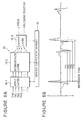
- Figure 4A illustrates an acoustic model of the guitar, wherein BRIDGE corresponds to the bridge 4 shown in Figure 1, PICKUP corresponds to the six-string pickup 3 and FRET corresponds to each fret 5.
- FINGERED FRET designates one fret 5 on which the player's finger is placed.
- PLUCKING POSITION denotes the playing position where the string is picked. The string length between FINGERED FRET and PLUCKING POSITION is assumed D 1. The vibration propagates therebetween in a time t 1.
- the string length between PLUCKING POSITION and PICKUP is denoted by D 2, and the vibration transmission time therebetween is denoted by t 2.
- the string length between BRIDGE and PICKUP is assumed to be D 3, and the vibration transmission time therebetween is represented by t 3.
- the open length of the string is denoted by D 0
- the string length between BRIDGE and FINGERED FRET is denoted by DF
- DP the string length between BRIDGE and PLUCKING POSITION
- the string is picked at PLUCKING POSITION, a pulsive vibration wave is produced at PLUCKING POSITION and is transmitted in opposite directions.
- the rightward transmission of the vibration pulse is shown in Figure 4B, and the leftward transmission is shown in Figure 4C.
- the PICKUP detects a positive pulse or peak R 1 as illustrated on the time axis t in Figure 5.
- the pulse passed over PICKUP location is reflected at BRIDGE with phase inversion. Then, the pulse travels leftward and reaches PICKUP again at time TR 2.
- the reflected and returning pulse is detected at the time TR 2, which is illustrated as a negative pulse R 2 on the time axis t in Figure 5.
- the pulse is propagated further leftward, and is reflected at FINGERED FRET with phase inversion to thereby return rightward.
- the pulse reaches PICKUP for the third time.
- the pulse is detected by PICKUP at time TR 3, which is illustrated as a positive pulse R 3 on the time axis t in Figure 5.
- the pulse is transmitted between BRIDGE and FINGERED FRET repeatedly along the string in such a manner.
- the pulse is detected at time TL 2, which is illustrated as a positive pulse L 2 on the time axis t in Figure 5. Thereafter, the pulse is transmitted between BRIDGE and FINGERED FRET repeatedly along the string.
- the pitch namely the frequency of the vibration of the string, is determined by the length DF between BRIDGE and FINGERED FRET. It is understood, with reference to Figure 5, that the time interval or period TF between the pulse or peak R 1 detected by PICKUP and the next pulse or peak R 3 corresponds to the time required for the pulse to propagate the distance 2 ⁇ DF . Thus, the time interval TF corresponds to a period of the vibration generated in the string.
- Figure 6A illustrates a model of the neural network 15, which is comprised of at least three layers including an input layer 15-1, an intermediate layer 15-2 and an output layer 15-3, and further a weight coefficient memory 16.
- the neural network 15 learns in advance to generate pitch data based on input waveform data. The learning result is stored in the weight coefficient memory 16.
- each of the pulse peak timing data TN 0, TP 1, TN 1, TN 2 ... measured from a reference time shown in Figure 6B is inputted to the input layer 15-1.
- the input layer 15-1 multiplies the inputted data by weight coefficients react out from the weight coefficient memory 16.
- the intermediate layer 15-2 multiplies the outputted data from the input layer 15-1 by weight coefficients read out from the weight coefficient memory 16.
- the output layer 15-3 multiplies the outputted data from the intermediate layer 15-2 by weight coefficients read out from the weight coefficient memory 16.
- the neural network 15 may not be fed with the timing data of the peaks of the pulse, but may be fed with area data of the pulse or peak level data.
- the reference time in Figure 6B is set to the peak timing of the first detected pulse. However, the reference time may be determined in terms of a center of gravity of the pulse, or a timing when the pulse crosses a certain threshold level.
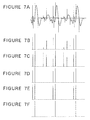
- the steepness data D which can be used in the pitch detection is processed to extract significant ones.
- an envelope data ENV 1 is multiplied by a constant coefficient F1 to derive reference envelope data ( ENV 1 ⁇ F 1).
- the steepness data D is compared with the reference envelope data ( ENV 1 ⁇ F 1). This comparison is illustrated in Figure 7C, wherein the steepness data D is shown in solid lines while the reference envelope data ( ENV 1 ⁇ F 1) is shown in dashed lines. With the comparison of the steepness data D and the reference envelope data ( ENV 1 ⁇ F 1), the data of a greater level is left as being valid.
- the relevant steepness data D is deleted, and the reference envelope data ( ENV 1 ⁇ F 1) is defined as a new envelope data ENV 1. Then, the steepness data left as being valid is multiplied with the coefficient F1 to derive a new reference envelope data ( ENV 1 ⁇ F 1) to be used for next comparison with next steepness data D . Thereafter, the same comparison procedure is repeated.
- the valid steepness data D is extracted as shown in Figure 7D. As illustrated in Figure 7D, four of the steepness data D having smaller values are deleted. However, in this stage, the pitch cannot be detected from the left steepness data D . Further extraction procedure for the left steepness data D is continued.
- the further extraction process is similar to the previous extraction procedure as described above, except that reference envelope data ( ENV 2 ⁇ F 2) (multiplied with a coefficient F2) is used here.
- the reference envelope data ( ENV 2 ⁇ F 2) is illustrated in dashed lines adjacent to corresponding ones of the steepness data D shown in solid lines.
- unwanted steepness data D are further deleted so that the final steepness data D are derived as shown in Figure 7F.
- the pitch of the tone can be detected accurately by measuring the duration between a pair of the final steepness data D shown in Figure 7F.
- the detected pitch data is distributed to the comparator 17.
- the input data is digitized as sampling data A 0, A 1, A 2, A 3 ... at sampling timings P 0, P 1, P 2, P 3 ... as shown in Figure 8B.
- the zero-cross timings and the sampling data timings may not coincide with each other. Therefore, the zero-cross points are determined using interpolation.
- the steepness of the waveform signal at zero-cross is evaluated so that the zero-cross points should be measured accurately.
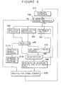
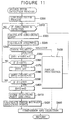
- the signal processing executed in the arrangement shown in Figure 3 is illustrated in Figure 9.
- the process is comprised of several subprocesses, and the subprocesses are executed repeatedly in loop.
- the envelope follower 11 executes the process of steps S10 to S30.
- the envelope of the vibration waveform signal is picked up in step S10.
- step S20 it is tested whether the detected envelope level is greater than a threshold level or not. If the string of the guitar is picked to issue a note-on event, the envelope exceeds the threshold level so that the test result shows "yes". Then, the velocity is determined from the detected envelope.
- step S20 results in "no", so that the procedure branches to step S100, where the same procedure is executed for a next string.
- the processing shown in Figure 9 is repeated for the six strings one by one.
- step S20 If the result of the test in step S20 is "yes", the first pitch detection processing in step S50 and the second pitch detection processing in step S40 are started, so that the three processings in steps S30, S40, and S50 are executed in parallel.
- the operations of the first and the second pitch detectors 13 and 12 are executed respectively in the first and the second pitch detection processings in steps S50 and S40. These detection processings respectively produce their output results.
- step S60 it is tested which of the first and second pitch detection processings outputs the pitch data faster than the other. If the first pitch detection process in step S50 outputs the pitch data faster, the selected first pitch detection data and the plucking position data are sent to the quantization process in step S80.
- the selection of the pitch data in step S60 is executed by the comparator 17 shown in Figure 3. If the first pitch detection process in step S50 fails to detect the first pitch data, the failure is noticed to the comparator 17 in step S60. Upon the failure, the second pitch data from the second pitch detection process is selected in place of the first pitch data. The selected second pitch data is sent to the quantization process in step S80 together with default plucking position data derived in step S70. Since the first pitch detection process is executed by the neural network, the pitch can be detected at high speed even at the initial period of the vibration wave after the note-on event. On the other hand, the second pitch detection process accurately detects the pitch by extracting the zero-cross points of the fundamental pitch.
- the detection accuracy is not so good as the first pitch detection process especially in an initial term just after the note-on event, but after that term, the detection accuracy becomes better than that of the first pitch detection.
- the comparison in step S60 it is possible to output the first pitch data detected by the first pitch detection process in the initial duration just after the note-on event, and thereafter the second pitch data from the second pitch detection process is selected in order to provide accurate pitch information at high speed. Otherwise, it is possible to substitute the first pitch data from, the first pitch detection process with the second pitch data from the second pitch detection process as soon as the second pitch detection process starts to output the pitch data.
- step S50 If the first pitch detection in step S50 fails to produce an output, the procedure branches from step S60 to step S110 in order to teach the neural network.
- a learning controller instructs the neural network 15 to execute learning. The actual learning is done in step S120.
- the learning is executed by a back-propagation method using the pitch data generated by the second pitch detecting process.
- the pitch can be detected by the first pitch detection process when a next similar data is inputted. After these processes are done, the procedure goes forward to step S100, where the similar process is executed for the remaining strings.
- step S200 The pulse detection in step S200 is repeated until a pulse is actually detected.
- step S220 the procedure branches to S250, in which it is tested whether a 110% time length of the open string vibration period is elapsed from the beginning of the step S200. This test is done with watching an output of a timer, which is reset at the beginning of the first pitch detection process. If the time is elapsed in step S250, the failure of the first pitch detection is noticed in step S260 to the comparison process of step S60, because the first pitch detection process should detect a pitch in the first period of the vibration.
- step S60 After the first pitch detection processing described above is finished, the comparison in step S60 is launched.
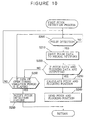
- the second pitch detection process is shown in a flowchart of Figure 11. Upon commencing the second pitch detection, unnecessary frequency components are eliminated by applying low-pass filtering process to the input vibration signal in step S300. Then, a zero-cross of the input vibration signal is detected in step S310. If the zero-cross is detected, the interpolating process illustrated in Figure 8B is conducted in step S320 in order to determine the accurate zero-cross point. Further in step S330, the steepness data is calculated in terms of the angle by which the vibration waveform crosses the time axis in step S330. In step S340, the polarity of the calculated steepness data is tested. If the steepness data is positive, the coefficient F1 is multiplied with the envelope data ENV 1 to derive new envelope data ENV 1 in step S350.
- step S360 it is tested whether the value of the steepness data D exceeds the calculated envelope data ENV 1 or not. If the result of this test is "yes", the steepness data D is set to a new envelope data ENV 1 in step S370 for use in a next loop. If the value of the steepness data D does not exceed the envelope data ENV 1 ("no" result in step S360), the procedure returns to step S310, where the steepness data D at the next zero-cross is calculated, and the steepness data D will be compared again with the envelope data ENV 1 in step S360. These processings are shown in Figures 7B, 7C and 7D.
- a new envelope data ENV 2 is calculated by multiplying the coefficient F2 with old ENV 2 in step S380. Then, in step S390, it is tested whether the value of the steepness data D exceeds the calculated envelope data ENV 2 or not. If the result of this test is "yes", the steepness data D is set to a new envelope data ENV 2 in step S400 for use in the next loop. In step S410, the detected zero-cross point and the envelope data ENV 2 are stored in a memory. In this case, the envelope data ENV 2 is equivalent to the steepness data D . This process is shown in Figures 7E and 7F.
- step S420 when two or more of the data are stored, the pitch is calculated and outputted by measuring the intermediate interval between the zero-cross points. If the stored zero-cross points are just two, it means that the pitch is detected in one period of the string vibration. The detection reliability is low in the initial phase of the detecting process, hence it is desirable to postpone the output in order to achieve more accurate data process such as average calculation.
- step S80 The quantization process in step S80 will be explained in detail hereunder.
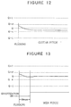
- the pitch shift or pitch transition after picking of a string of the guitar is shown in Figure 12.
- a level Q in the figure denotes a regular pitch
- Q + 1 and Q - 1 respectively denote half step (semitone) higher and lower pitches.
- the finger may move off in the direction perpendicular to the string.
- the pitch in stable phase offsets from Q as shown in Figure 12.
- a range Q ⁇ d including the pitch Q as the central level is quantized to the normal value Q . This sort of the process is called the quantization.
- the conventional pitch quantization is illustrated in Figure 14, wherein the pitch detector outputs the pitch data, and the quantization mode is tested if it is "on” or “off” in step S500.
- the quantization mode can be set according to the user's intention. If the user sets the mode to "off”, the procedure branches to step S520, in which the input pitch data is translated into MIDI data for output. Otherwise, if the quantization mode is "on”, the procedure branches to step S510, where the input pitch data is added with a value 0.5, and then the integer portion of the added result is output as a pitch data P .
- the value "0.5" means the half of semitone (quarter-tone) here.
- the quantization is actually carried out in this step S510.
- step S520 the pitch data is converted into the MIDI data format, and the derived MIDI data is outputted.
- the quantizing process is commenced with 40 msec delay after the note-on event to preserve the pitch fall phenomenon.
- This treatment is illustrated in Figure 13, wherein the quantizing is executed with some interpolation to smoothly shift to the regular pitch level Q . Otherwise, the pitch might change stepwise at the beginning of the quantization.
- the resulted final pitch data is converted into MIDI data for output.
- the preset delay in the quantizing is not limited to 40 msec, and it may be 20 to 100 msec.
- the quantization described above refines the tone of the "attack" phase.
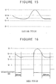
- the quantization is executed even in case that the player intentionally performs bending or choking of the string, the pitch will be changed stepwise due to the quantization and the tone may sound unnatural.
- it is expedient to turn off the quantization if the string bending is performed as shown in Figure 15, wherein the player performs the string bending after the note-on.
- the natural pitch-bending tone can be reproduced, but the pitch cannot be corrected in case that the unintentional offset fingering occurs. If the pitch is not stable, it is difficult to play chord.
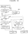
- step S580 After the smoothening interpolation by an interpolator in step S580, the pitch data is converted into the MIDI data format, and the derived MIDI data is outputted in step S590. If the quantization mode is set in "auto”, a pitch-bend detector detects existence of any pitch-bending in step S560. If the pitch returns within the range Q ⁇ d , this detection results in "no” so that the quantization of step S570 is executed. On the other hand, if the pitch changes over the range Q ⁇ d , the pitch bending detection results in "yes”, and the automatic quantization processing illustrated in Figure 16 is executed.
- step S660 results in "no" so that the quantizing process is turned on for the pitch quantization. If the player bends or chokes the string at this stage, the pitch data shifts out of the range Q ⁇ d.
- step S620 results in "yes", and then the turning off of the timer is tested in step S630.
- step S640 the interpolation is executed in step S640.
- step S650 the timer is set to 220 msec in step S650.
- step S660 the timer is detected as being turned on, so that the quantization process is disabled. As described above, if the pitch bending is detected for the pitch data P (step S620), the quantization process is disabled, and the inputted pitch data P is outputted as it is.
- step S630 results in "no"
- the timer is set to 220 msec again.
- step S660 results in "no" after the 220 msec count of the timer, so that the quantization is enabled. Therefore, the quantization process shown in Figure 17 is carried out in step S570, and then the smoothening interpolation process is done in step S580 so that the pitch data converted into the MIDI data is outputted.
- the accurate pitch data can be derived at high speed.
- the 40 msec period set to the timer upon note-on in Figure 18 may be altered to 20 to 100 msec, while the 220 msec period set to the timer upon pitch bending detection can be modified within a range of 100 to 1000 msec.
- the guitar with steel strings is assumed.
- the string may be composed of nylon.
- the pickup to detect the string vibration may be other types such as a piezo pickup mounted in the bridge of the instrument.
- the first pitch detector to detect the pitch at high speed may be other types which do not employ the neural network, and the detection result may be outputted just after every vibration signal input. In the explanation above, the pitch of the string vibration is detected.
- the present invention is not limited to that extent, and can be applied to any other pitch detection processes on external voice and external sound.
- the invention of the pitch detecting method can employ first and second pitch detectors of various types utilizing specific methods such as autocorrelation method and other zero-cross detection methods.
- FIG 19 shows another embodiment of the inventive electronic musical apparatus.
- This embodiment basically has the same construction as that of the previous embodiment shown in Figure 3. Therefore, corresponding blocks are denoted by the same reference numerals as those of the previous embodiment to facilitate understanding of this embodiment.
- the electronic musical apparatus is implemented by a computer system in which all of the functional blocks except for the acoustic instrument such as guitar are integrated altogether in the form of software modules, and are controlled by the controller 21 made of CPU through a system bus (not shown).
- the system is operated according to an application program loaded into the controller 21 by means of a machine-readable media 25 such as an optical memory disc and a magnetic memory disc.
- the second detector 12 is operated in parallel to the first detector 13 for processing the same waveform signal according to a slow algorithm so as to stably produce a second output representative of the pitch of the acoustic vibration.
- the selector in the form of the comparator 17 is operated for selectively feeding one of the first output and the second output to the tone generator 20 so that the first detector 13 and the second detector 12 can cooperate complementarily with each other to ensure responsive and stable detection of the pitch of the acoustic vibration.
- the first detector 13 is operated for calculating a time interval between two peaks successively contained in the waveform signal according to the fast algorithm so as to roughly detect the pitch, while the second detector 12 is operated for calculating an average of time intervals among three or more peaks successively contained in the waveform signal according to the slow algorithm so as to finely detect the pitch.
- the selector 17 is operated during an initial period immediately after the acoustic vibration is commenced for selecting the first output, and is operated after the initial period has passed for selecting the second output.
- the selector 17 is operated for switching from the first output to the second output when the second detector 12 succeedingly becomes effective to produce the second output after the first detector 13 precedingly becomes effective to produce the first output.
- the selector 17 is operated when the first detector 13 fails to produce the first output for selecting the second output in place of the missing first output.
- the first detector 13 operates the neural network 15 for learning the processing of the waveform signal according to teaching information to improve detection of the pitch, and the selector 17 is operated when the first detector 13 does not operate well for providing the second output as the teaching information to the first detector 13.
- the variation detector in the controller 21 connected to either of the first detector 13 and the second detector 12 is operated for detecting variation of the pitch of the acoustic vibration.
- the quantizer 18 connected between the selector 17 and the tone generator 20 is operated when the detected variation falls within a predetermined range for quantizing the selected one of the first output and the second output to a fixed pitch so as to remove unintentional fluctuation of the acoustic vibration.
- the controller 21 is operated when the detected variation falls out of the predetermined range for disabling the quantizer 18 to feed the selected one of the first output and the second output as it is to the tone generator 20 to thereby reserve intentional deviation of the acoustic vibration.
- the quantizer 18 is operated for quantizing the selected one of the first output and the second output to fix the pitch of the musical tone so as to remove fluctuation of the acoustic vibration.
- the controller 21 is operated during an initial period from the commencing of the acoustic vibration for suppressing the quantizer 18 to feed the selected one of the first output and the second output as it is to the tone generator 20 so that the musical tone reserves an attack part of the acoustic vibration.
- Either of the first detector 13 and the second detector 12 is operated for detecting the pitch of the acoustic vibration commenced by plucking a stringed acoustic instrument at a variable plucking point, and for detecting the plucking point according to the waveform signal so that a timbre of the musical tone can be controlled according to the detected plucking point.
- the controller 21 is operated depending on a specific condition of the acoustic vibration for temporarily disabling the quantizer 18 so as to feed the detected pitch as it is to the tone generator 20 so that the generated musical tone temporarily maintains the detected pitch which reflects the specific condition of the acoustic vibration.
- the controller 21 is operated for detecting variation of the successively detected pitch.
- the controller 21 is operated when the detected variation falls within a predetermined range under a normal condition for enabling the quantizer 18 , and is operated when the detected variation falls out of the predetermined range under a specific condition for disabling the quantizer 18.
- the controller 21 is operated during an initial period from the commencement of the acoustic vibration for disabling the quantizer 18, and is operated after the initial period has passed for enabling the quantizer 18.
Landscapes
- Engineering & Computer Science (AREA)
- Physics & Mathematics (AREA)
- Acoustics & Sound (AREA)
- Multimedia (AREA)
- Signal Processing (AREA)
- Electrophonic Musical Instruments (AREA)
- Measurement Of Mechanical Vibrations Or Ultrasonic Waves (AREA)
Applications Claiming Priority (3)
| Application Number | Priority Date | Filing Date | Title |
|---|---|---|---|
| JP7173038A JP2805598B2 (ja) | 1995-06-16 | 1995-06-16 | 演奏位置検出方法およびピッチ検出方法 |
| JP17303895 | 1995-06-16 | ||
| EP96109542A EP0749107B1 (fr) | 1995-06-16 | 1996-06-13 | Synthétiseur détectant la hauteur et le point de départ d'une note d'instrument à cordes pour la génération de notes |
Related Parent Applications (2)
| Application Number | Title | Priority Date | Filing Date |
|---|---|---|---|
| EP96109542A Division EP0749107B1 (fr) | 1995-06-16 | 1996-06-13 | Synthétiseur détectant la hauteur et le point de départ d'une note d'instrument à cordes pour la génération de notes |
| EP96109542A Division-Into EP0749107B1 (fr) | 1995-06-16 | 1996-06-13 | Synthétiseur détectant la hauteur et le point de départ d'une note d'instrument à cordes pour la génération de notes |
Publications (3)
| Publication Number | Publication Date |
|---|---|
| EP0994460A2 true EP0994460A2 (fr) | 2000-04-19 |
| EP0994460A3 EP0994460A3 (fr) | 2000-05-03 |
| EP0994460B1 EP0994460B1 (fr) | 2001-10-04 |
Family
ID=15953059
Family Applications (3)
| Application Number | Title | Priority Date | Filing Date |
|---|---|---|---|
| EP96109542A Expired - Lifetime EP0749107B1 (fr) | 1995-06-16 | 1996-06-13 | Synthétiseur détectant la hauteur et le point de départ d'une note d'instrument à cordes pour la génération de notes |
| EP99125405A Expired - Lifetime EP0994460B1 (fr) | 1995-06-16 | 1996-06-13 | Synthétiseur détectant la hauteur d'une note et la position à laquelle une corde est grattée sur un instrument à cordes pour la génération de notes |
| EP99125444A Expired - Lifetime EP0987678B1 (fr) | 1995-06-16 | 1996-06-13 | Synthétiseur détectant la hauteur d'une note et la position grattée sur un instrument à cordes pour la génération de notes |
Family Applications Before (1)
| Application Number | Title | Priority Date | Filing Date |
|---|---|---|---|
| EP96109542A Expired - Lifetime EP0749107B1 (fr) | 1995-06-16 | 1996-06-13 | Synthétiseur détectant la hauteur et le point de départ d'une note d'instrument à cordes pour la génération de notes |
Family Applications After (1)
| Application Number | Title | Priority Date | Filing Date |
|---|---|---|---|
| EP99125444A Expired - Lifetime EP0987678B1 (fr) | 1995-06-16 | 1996-06-13 | Synthétiseur détectant la hauteur d'une note et la position grattée sur un instrument à cordes pour la génération de notes |
Country Status (5)
| Country | Link |
|---|---|
| US (1) | US5717155A (fr) |
| EP (3) | EP0749107B1 (fr) |
| JP (1) | JP2805598B2 (fr) |
| KR (1) | KR100308865B1 (fr) |
| DE (3) | DE69615284T2 (fr) |
Families Citing this family (24)
| Publication number | Priority date | Publication date | Assignee | Title |
|---|---|---|---|---|
| JP3534932B2 (ja) * | 1996-01-26 | 2004-06-07 | ローランド株式会社 | 電子弦楽器の楽音制御装置 |
| JP3424787B2 (ja) * | 1996-03-12 | 2003-07-07 | ヤマハ株式会社 | 演奏情報検出装置 |
| DE19649296C2 (de) * | 1996-11-28 | 2002-01-17 | Blue Chip Music Gmbh | Verfahren zur Tonhöhenerkennung bei zupf- oder schlagerregten Saiteninstrumenten |
| GB9722985D0 (en) * | 1996-12-20 | 1998-01-07 | Univ York | Tuning of musical instruments |
| US6610917B2 (en) * | 1998-05-15 | 2003-08-26 | Lester F. Ludwig | Activity indication, external source, and processing loop provisions for driven vibrating-element environments |
| JP4084470B2 (ja) * | 1998-08-25 | 2008-04-30 | 株式会社コルグ | 調律器 |
| JP2001218204A (ja) * | 2000-01-31 | 2001-08-10 | Canon Inc | データ処理方法及び装置並びに記憶媒体 |
| JP2002258860A (ja) * | 2001-03-05 | 2002-09-11 | Roland Corp | 電子楽器 |
| JP3671876B2 (ja) * | 2001-06-29 | 2005-07-13 | ヤマハ株式会社 | 楽音発生装置 |
| EP1793370B1 (fr) * | 2001-08-31 | 2009-06-03 | Kabushiki Kaisha Kenwood | Appareil et procédé pour la création de signaux de fréquence fondamentale constante et appareil et procédé pour synthétiser des signaux de parole utilisant ces signaux de fréquence fondamentale constante |
| JP3941707B2 (ja) * | 2003-02-17 | 2007-07-04 | ヤマハ株式会社 | 電子楽器 |
| RU2248532C1 (ru) * | 2003-08-14 | 2005-03-20 | Бакин Виктор Александрович | Электромеханическое программируемое приспособление для игры на гитаре "бекар"(варианты) |
| JP4198046B2 (ja) * | 2003-12-26 | 2008-12-17 | ローランド株式会社 | 電子弦楽器 |
| US20060048635A1 (en) * | 2004-09-09 | 2006-03-09 | Jack Campbell | System for digitally transmitting audio data from individual electric guitar strings |
| JP4296433B2 (ja) * | 2005-06-20 | 2009-07-15 | カシオ計算機株式会社 | 入力制御装置および入力制御プログラム |
| US7563975B2 (en) * | 2005-09-14 | 2009-07-21 | Mattel, Inc. | Music production system |
| AU2009206663A1 (en) * | 2008-01-24 | 2009-07-30 | 745 Llc | Method and apparatus for stringed controllers and/or instruments |
| JP5605192B2 (ja) * | 2010-12-02 | 2014-10-15 | ヤマハ株式会社 | 楽音信号合成方法、プログラムおよび楽音信号合成装置 |
| JP6171347B2 (ja) | 2013-01-08 | 2017-08-02 | カシオ計算機株式会社 | 電子弦楽器、楽音生成方法及びプログラム |
| US9243950B2 (en) | 2013-03-15 | 2016-01-26 | First Principles, Inc. | Method and device for analyzing resonance |
| JP2014238550A (ja) * | 2013-06-10 | 2014-12-18 | カシオ計算機株式会社 | 楽音発生装置、楽音発生方法及びプログラム |
| US9626947B1 (en) * | 2015-10-21 | 2017-04-18 | Kesumo, Llc | Fret scanners and pickups for stringed instruments |
| WO2017182533A1 (fr) * | 2016-04-19 | 2017-10-26 | Universiteit Gent | Procédé et système pour jouer des instruments de musique |
| JP6852786B2 (ja) | 2017-04-20 | 2021-03-31 | ヤマハ株式会社 | 機械学習装置、情報処理装置及び出力装置 |
Family Cites Families (12)
| Publication number | Priority date | Publication date | Assignee | Title |
|---|---|---|---|---|
| US4151775A (en) * | 1977-08-31 | 1979-05-01 | Merriman George W | Electrical apparatus for determining the pitch or fundamental frequency of a musical note |
| JPS5587196A (en) * | 1978-12-23 | 1980-07-01 | Nippon Musical Instruments Mfg | External music tone input type electronic musical instrument |
| JPS6090396A (ja) * | 1983-10-24 | 1985-05-21 | セイコーインスツルメンツ株式会社 | 音声認識式音程採譜装置 |
| US4723468A (en) * | 1985-10-26 | 1988-02-09 | Nippon Gakki Seizo Kabushiki Kaisha | Electronic stringed instrument |
| JPH07101344B2 (ja) * | 1987-04-22 | 1995-11-01 | ヤマハ株式会社 | 電子弦楽器 |
| JPH01177082A (ja) * | 1987-12-28 | 1989-07-13 | Casio Comput Co Ltd | 音高決定装置 |
| JP2734521B2 (ja) * | 1988-03-31 | 1998-03-30 | カシオ計算機株式会社 | 楽音制御装置 |
| JP3020504B2 (ja) * | 1988-06-10 | 2000-03-15 | カシオ計算機株式会社 | 楽音制御装置 |
| US5001960A (en) * | 1988-06-10 | 1991-03-26 | Casio Computer Co., Ltd. | Apparatus for controlling reproduction on pitch variation of an input waveform signal |
| JP2775633B2 (ja) * | 1988-12-23 | 1998-07-16 | カシオ計算機株式会社 | 楽音制御装置 |
| US5138924A (en) * | 1989-08-10 | 1992-08-18 | Yamaha Corporation | Electronic musical instrument utilizing a neural network |
| JPH0594191A (ja) * | 1991-10-01 | 1993-04-16 | Roland Corp | 電気弦楽器用ピツクアツプの周波数特性補償装置 |
-
1995
- 1995-06-16 JP JP7173038A patent/JP2805598B2/ja not_active Expired - Fee Related
-
1996
- 1996-06-13 DE DE69615284T patent/DE69615284T2/de not_active Expired - Lifetime
- 1996-06-13 EP EP96109542A patent/EP0749107B1/fr not_active Expired - Lifetime
- 1996-06-13 EP EP99125405A patent/EP0994460B1/fr not_active Expired - Lifetime
- 1996-06-13 US US08/662,474 patent/US5717155A/en not_active Expired - Lifetime
- 1996-06-13 DE DE69615716T patent/DE69615716T2/de not_active Expired - Fee Related
- 1996-06-13 DE DE69614723T patent/DE69614723T2/de not_active Expired - Fee Related
- 1996-06-13 EP EP99125444A patent/EP0987678B1/fr not_active Expired - Lifetime
- 1996-06-15 KR KR1019960021666A patent/KR100308865B1/ko not_active Expired - Fee Related
Also Published As
| Publication number | Publication date |
|---|---|
| EP0994460A3 (fr) | 2000-05-03 |
| KR100308865B1 (ko) | 2001-12-17 |
| KR970002841A (ko) | 1997-01-28 |
| US5717155A (en) | 1998-02-10 |
| EP0987678A3 (fr) | 2000-04-05 |
| EP0749107A2 (fr) | 1996-12-18 |
| DE69615716D1 (de) | 2001-11-08 |
| EP0749107B1 (fr) | 2001-09-19 |
| JPH096339A (ja) | 1997-01-10 |
| EP0749107A3 (fr) | 1997-01-08 |
| DE69614723T2 (de) | 2002-06-27 |
| DE69615284T2 (de) | 2002-06-27 |
| EP0987678A2 (fr) | 2000-03-22 |
| JP2805598B2 (ja) | 1998-09-30 |
| DE69615284D1 (de) | 2001-10-25 |
| EP0987678B1 (fr) | 2001-08-22 |
| EP0994460B1 (fr) | 2001-10-04 |
| DE69614723D1 (de) | 2001-09-27 |
| DE69615716T2 (de) | 2002-07-11 |
Similar Documents
| Publication | Publication Date | Title |
|---|---|---|
| EP0994460B1 (fr) | Synthétiseur détectant la hauteur d'une note et la position à laquelle une corde est grattée sur un instrument à cordes pour la génération de notes | |
| US7124084B2 (en) | Singing voice-synthesizing method and apparatus and storage medium | |
| KR920010919B1 (ko) | 전자 현악기 | |
| US5014589A (en) | Control apparatus for electronic musical instrument for generating musical tone having tone pitch corresponding to input waveform signal | |
| JPH09127937A (ja) | 楽音パラメータ制御装置 | |
| JP3653854B2 (ja) | 弦楽器型電子楽器 | |
| US5001960A (en) | Apparatus for controlling reproduction on pitch variation of an input waveform signal | |
| US5048391A (en) | Electronic musical instrument for generating musical tones on the basis of characteristics of input waveform signal | |
| JPH1039863A (ja) | 自動伴奏装置 | |
| US5945621A (en) | Musical tone control apparatus with envelope processing | |
| JP2532424B2 (ja) | 波形信号入力制御装置 | |
| JP3307162B2 (ja) | 音楽制御装置 | |
| JP2611263B2 (ja) | 発音制御装置 | |
| JP3020504B2 (ja) | 楽音制御装置 | |
| JP2661066B2 (ja) | 発音制御装置 | |
| JP2591001B2 (ja) | 電子弦楽器 | |
| JP3471480B2 (ja) | テンポ制御装置 | |
| JP2661065B2 (ja) | 発音制御装置 | |
| JP2605773B2 (ja) | 電子弦楽器 | |
| JP2591000B2 (ja) | 電子弦楽器 | |
| JP2759149B2 (ja) | 楽音制御装置 | |
| JPH09319365A (ja) | 弦楽器用ピッチ検出装置 | |
| JPH08272363A (ja) | テンポ制御装置 | |
| JPH05232950A (ja) | 電子弦楽器 | |
| JPH08254980A (ja) | 演奏データ記録装置 |
Legal Events
| Date | Code | Title | Description |
|---|---|---|---|
| PUAI | Public reference made under article 153(3) epc to a published international application that has entered the european phase |
Free format text: ORIGINAL CODE: 0009012 |
|
| PUAL | Search report despatched |
Free format text: ORIGINAL CODE: 0009013 |
|
| 17P | Request for examination filed |
Effective date: 19991220 |
|
| AC | Divisional application: reference to earlier application |
Ref document number: 749107 Country of ref document: EP |
|
| AK | Designated contracting states |
Kind code of ref document: A2 Designated state(s): DE GB IT |
|
| AK | Designated contracting states |
Kind code of ref document: A3 Designated state(s): DE GB IT |
|
| 17Q | First examination report despatched |
Effective date: 20000918 |
|
| GRAG | Despatch of communication of intention to grant |
Free format text: ORIGINAL CODE: EPIDOS AGRA |
|
| AKX | Designation fees paid |
Free format text: DE GB IT |
|
| GRAG | Despatch of communication of intention to grant |
Free format text: ORIGINAL CODE: EPIDOS AGRA |
|
| GRAH | Despatch of communication of intention to grant a patent |
Free format text: ORIGINAL CODE: EPIDOS IGRA |
|
| GRAH | Despatch of communication of intention to grant a patent |
Free format text: ORIGINAL CODE: EPIDOS IGRA |
|
| GRAA | (expected) grant |
Free format text: ORIGINAL CODE: 0009210 |
|
| AC | Divisional application: reference to earlier application |
Ref document number: 749107 Country of ref document: EP |
|
| AK | Designated contracting states |
Kind code of ref document: B1 Designated state(s): DE GB IT |
|
| REF | Corresponds to: |
Ref document number: 69615716 Country of ref document: DE Date of ref document: 20011108 |
|
| REG | Reference to a national code |
Ref country code: GB Ref legal event code: IF02 |
|
| PLBE | No opposition filed within time limit |
Free format text: ORIGINAL CODE: 0009261 |
|
| STAA | Information on the status of an ep patent application or granted ep patent |
Free format text: STATUS: NO OPPOSITION FILED WITHIN TIME LIMIT |
|
| 26N | No opposition filed | ||
| PGFP | Annual fee paid to national office [announced via postgrant information from national office to epo] |
Ref country code: GB Payment date: 20040609 Year of fee payment: 9 |
|
| PGFP | Annual fee paid to national office [announced via postgrant information from national office to epo] |
Ref country code: DE Payment date: 20040624 Year of fee payment: 9 |
|
| PG25 | Lapsed in a contracting state [announced via postgrant information from national office to epo] |
Ref country code: IT Free format text: LAPSE BECAUSE OF NON-PAYMENT OF DUE FEES Effective date: 20050613 Ref country code: GB Free format text: LAPSE BECAUSE OF NON-PAYMENT OF DUE FEES Effective date: 20050613 |
|
| PG25 | Lapsed in a contracting state [announced via postgrant information from national office to epo] |
Ref country code: DE Free format text: LAPSE BECAUSE OF NON-PAYMENT OF DUE FEES Effective date: 20060103 |
|
| GBPC | Gb: european patent ceased through non-payment of renewal fee |
Effective date: 20050613 |