EP0994466A2 - Magneto-optische Kopfvorrichtung mit integrierter Hilfslinse und magneto-optischer Wiedergabekopf und die magneto-optische Kopfvorrichtung benutzende Aufzeichnungs - und Wiedergabevorrichtung - Google Patents
Magneto-optische Kopfvorrichtung mit integrierter Hilfslinse und magneto-optischer Wiedergabekopf und die magneto-optische Kopfvorrichtung benutzende Aufzeichnungs - und Wiedergabevorrichtung Download PDFInfo
- Publication number
- EP0994466A2 EP0994466A2 EP99120477A EP99120477A EP0994466A2 EP 0994466 A2 EP0994466 A2 EP 0994466A2 EP 99120477 A EP99120477 A EP 99120477A EP 99120477 A EP99120477 A EP 99120477A EP 0994466 A2 EP0994466 A2 EP 0994466A2
- Authority
- EP
- European Patent Office
- Prior art keywords
- recording
- head
- magneto
- magnetic
- recording medium
- Prior art date
- Legal status (The legal status is an assumption and is not a legal conclusion. Google has not performed a legal analysis and makes no representation as to the accuracy of the status listed.)
- Withdrawn
Links
- 230000003287 optical effect Effects 0.000 claims description 42
- 239000011521 glass Substances 0.000 claims description 7
- 239000000463 material Substances 0.000 claims description 7
- 239000011248 coating agent Substances 0.000 claims description 4
- 238000000576 coating method Methods 0.000 claims description 4
- 230000003247 decreasing effect Effects 0.000 abstract description 8
- 238000000034 method Methods 0.000 description 26
- 239000000758 substrate Substances 0.000 description 21
- 239000007787 solid Substances 0.000 description 11
- 238000004519 manufacturing process Methods 0.000 description 8
- 101100298998 Caenorhabditis elegans pbs-3 gene Proteins 0.000 description 5
- 238000001514 detection method Methods 0.000 description 5
- 239000000284 extract Substances 0.000 description 5
- 238000007654 immersion Methods 0.000 description 5
- 230000005415 magnetization Effects 0.000 description 5
- 230000004907 flux Effects 0.000 description 4
- 230000006870 function Effects 0.000 description 4
- 230000001939 inductive effect Effects 0.000 description 4
- 230000008859 change Effects 0.000 description 3
- 239000002131 composite material Substances 0.000 description 3
- 230000007423 decrease Effects 0.000 description 3
- 230000008569 process Effects 0.000 description 3
- 230000001360 synchronised effect Effects 0.000 description 3
- 239000010409 thin film Substances 0.000 description 3
- 230000000694 effects Effects 0.000 description 2
- 239000011347 resin Substances 0.000 description 2
- 229920005989 resin Polymers 0.000 description 2
- 238000011144 upstream manufacturing Methods 0.000 description 2
- 230000003321 amplification Effects 0.000 description 1
- 238000010586 diagram Methods 0.000 description 1
- 230000001678 irradiating effect Effects 0.000 description 1
- 238000003199 nucleic acid amplification method Methods 0.000 description 1
- 239000012782 phase change material Substances 0.000 description 1
- 230000010287 polarization Effects 0.000 description 1
- 229920006395 saturated elastomer Polymers 0.000 description 1
- 230000004304 visual acuity Effects 0.000 description 1
Images





Classifications
-
- G—PHYSICS
- G11—INFORMATION STORAGE
- G11B—INFORMATION STORAGE BASED ON RELATIVE MOVEMENT BETWEEN RECORD CARRIER AND TRANSDUCER
- G11B5/00—Recording by magnetisation or demagnetisation of a record carrier; Reproducing by magnetic means; Record carriers therefor
-
- G—PHYSICS
- G11—INFORMATION STORAGE
- G11B—INFORMATION STORAGE BASED ON RELATIVE MOVEMENT BETWEEN RECORD CARRIER AND TRANSDUCER
- G11B11/00—Recording on or reproducing from the same record carrier wherein for these two operations the methods are covered by different main groups of groups G11B3/00 - G11B7/00 or by different subgroups of group G11B9/00; Record carriers therefor
- G11B11/10—Recording on or reproducing from the same record carrier wherein for these two operations the methods are covered by different main groups of groups G11B3/00 - G11B7/00 or by different subgroups of group G11B9/00; Record carriers therefor using recording by magnetic means or other means for magnetisation or demagnetisation of a record carrier, e.g. light induced spin magnetisation; Demagnetisation by thermal or stress means in the presence or not of an orienting magnetic field
- G11B11/105—Recording on or reproducing from the same record carrier wherein for these two operations the methods are covered by different main groups of groups G11B3/00 - G11B7/00 or by different subgroups of group G11B9/00; Record carriers therefor using recording by magnetic means or other means for magnetisation or demagnetisation of a record carrier, e.g. light induced spin magnetisation; Demagnetisation by thermal or stress means in the presence or not of an orienting magnetic field using a beam of light or a magnetic field for recording by change of magnetisation and a beam of light for reproducing, i.e. magneto-optical, e.g. light-induced thermomagnetic recording, spin magnetisation recording, Kerr or Faraday effect reproducing
-
- B—PERFORMING OPERATIONS; TRANSPORTING
- B82—NANOTECHNOLOGY
- B82Y—SPECIFIC USES OR APPLICATIONS OF NANOSTRUCTURES; MEASUREMENT OR ANALYSIS OF NANOSTRUCTURES; MANUFACTURE OR TREATMENT OF NANOSTRUCTURES
- B82Y10/00—Nanotechnology for information processing, storage or transmission, e.g. quantum computing or single electron logic
-
- B—PERFORMING OPERATIONS; TRANSPORTING
- B82—NANOTECHNOLOGY
- B82Y—SPECIFIC USES OR APPLICATIONS OF NANOSTRUCTURES; MEASUREMENT OR ANALYSIS OF NANOSTRUCTURES; MANUFACTURE OR TREATMENT OF NANOSTRUCTURES
- B82Y25/00—Nanomagnetism, e.g. magnetoimpedance, anisotropic magnetoresistance, giant magnetoresistance or tunneling magnetoresistance
-
- G—PHYSICS
- G11—INFORMATION STORAGE
- G11B—INFORMATION STORAGE BASED ON RELATIVE MOVEMENT BETWEEN RECORD CARRIER AND TRANSDUCER
- G11B11/00—Recording on or reproducing from the same record carrier wherein for these two operations the methods are covered by different main groups of groups G11B3/00 - G11B7/00 or by different subgroups of group G11B9/00; Record carriers therefor
- G11B11/10—Recording on or reproducing from the same record carrier wherein for these two operations the methods are covered by different main groups of groups G11B3/00 - G11B7/00 or by different subgroups of group G11B9/00; Record carriers therefor using recording by magnetic means or other means for magnetisation or demagnetisation of a record carrier, e.g. light induced spin magnetisation; Demagnetisation by thermal or stress means in the presence or not of an orienting magnetic field
- G11B11/105—Recording on or reproducing from the same record carrier wherein for these two operations the methods are covered by different main groups of groups G11B3/00 - G11B7/00 or by different subgroups of group G11B9/00; Record carriers therefor using recording by magnetic means or other means for magnetisation or demagnetisation of a record carrier, e.g. light induced spin magnetisation; Demagnetisation by thermal or stress means in the presence or not of an orienting magnetic field using a beam of light or a magnetic field for recording by change of magnetisation and a beam of light for reproducing, i.e. magneto-optical, e.g. light-induced thermomagnetic recording, spin magnetisation recording, Kerr or Faraday effect reproducing
- G11B11/10532—Heads
- G11B11/10534—Heads for recording by magnetising, demagnetising or transfer of magnetisation, by radiation, e.g. for thermomagnetic recording
- G11B11/10536—Heads for recording by magnetising, demagnetising or transfer of magnetisation, by radiation, e.g. for thermomagnetic recording using thermic beams, e.g. lasers
-
- G—PHYSICS
- G11—INFORMATION STORAGE
- G11B—INFORMATION STORAGE BASED ON RELATIVE MOVEMENT BETWEEN RECORD CARRIER AND TRANSDUCER
- G11B11/00—Recording on or reproducing from the same record carrier wherein for these two operations the methods are covered by different main groups of groups G11B3/00 - G11B7/00 or by different subgroups of group G11B9/00; Record carriers therefor
- G11B11/10—Recording on or reproducing from the same record carrier wherein for these two operations the methods are covered by different main groups of groups G11B3/00 - G11B7/00 or by different subgroups of group G11B9/00; Record carriers therefor using recording by magnetic means or other means for magnetisation or demagnetisation of a record carrier, e.g. light induced spin magnetisation; Demagnetisation by thermal or stress means in the presence or not of an orienting magnetic field
- G11B11/105—Recording on or reproducing from the same record carrier wherein for these two operations the methods are covered by different main groups of groups G11B3/00 - G11B7/00 or by different subgroups of group G11B9/00; Record carriers therefor using recording by magnetic means or other means for magnetisation or demagnetisation of a record carrier, e.g. light induced spin magnetisation; Demagnetisation by thermal or stress means in the presence or not of an orienting magnetic field using a beam of light or a magnetic field for recording by change of magnetisation and a beam of light for reproducing, i.e. magneto-optical, e.g. light-induced thermomagnetic recording, spin magnetisation recording, Kerr or Faraday effect reproducing
- G11B11/1055—Disposition or mounting of transducers relative to record carriers
- G11B11/10552—Arrangements of transducers relative to each other, e.g. coupled heads, optical and magnetic head on the same base
- G11B11/10554—Arrangements of transducers relative to each other, e.g. coupled heads, optical and magnetic head on the same base the transducers being disposed on the same side of the carrier
-
- G—PHYSICS
- G11—INFORMATION STORAGE
- G11B—INFORMATION STORAGE BASED ON RELATIVE MOVEMENT BETWEEN RECORD CARRIER AND TRANSDUCER
- G11B11/00—Recording on or reproducing from the same record carrier wherein for these two operations the methods are covered by different main groups of groups G11B3/00 - G11B7/00 or by different subgroups of group G11B9/00; Record carriers therefor
- G11B11/10—Recording on or reproducing from the same record carrier wherein for these two operations the methods are covered by different main groups of groups G11B3/00 - G11B7/00 or by different subgroups of group G11B9/00; Record carriers therefor using recording by magnetic means or other means for magnetisation or demagnetisation of a record carrier, e.g. light induced spin magnetisation; Demagnetisation by thermal or stress means in the presence or not of an orienting magnetic field
- G11B11/105—Recording on or reproducing from the same record carrier wherein for these two operations the methods are covered by different main groups of groups G11B3/00 - G11B7/00 or by different subgroups of group G11B9/00; Record carriers therefor using recording by magnetic means or other means for magnetisation or demagnetisation of a record carrier, e.g. light induced spin magnetisation; Demagnetisation by thermal or stress means in the presence or not of an orienting magnetic field using a beam of light or a magnetic field for recording by change of magnetisation and a beam of light for reproducing, i.e. magneto-optical, e.g. light-induced thermomagnetic recording, spin magnetisation recording, Kerr or Faraday effect reproducing
- G11B11/1055—Disposition or mounting of transducers relative to record carriers
- G11B11/1058—Flying heads
-
- G—PHYSICS
- G11—INFORMATION STORAGE
- G11B—INFORMATION STORAGE BASED ON RELATIVE MOVEMENT BETWEEN RECORD CARRIER AND TRANSDUCER
- G11B5/00—Recording by magnetisation or demagnetisation of a record carrier; Reproducing by magnetic means; Record carriers therefor
- G11B5/127—Structure or manufacture of heads, e.g. inductive
- G11B5/17—Construction or disposition of windings
-
- G—PHYSICS
- G11—INFORMATION STORAGE
- G11B—INFORMATION STORAGE BASED ON RELATIVE MOVEMENT BETWEEN RECORD CARRIER AND TRANSDUCER
- G11B7/00—Recording or reproducing by optical means, e.g. recording using a thermal beam of optical radiation by modifying optical properties or the physical structure, reproducing using an optical beam at lower power by sensing optical properties; Record carriers therefor
- G11B7/12—Heads, e.g. forming of the optical beam spot or modulation of the optical beam
- G11B7/122—Flying-type heads, e.g. analogous to Winchester type in magnetic recording
-
- G—PHYSICS
- G11—INFORMATION STORAGE
- G11B—INFORMATION STORAGE BASED ON RELATIVE MOVEMENT BETWEEN RECORD CARRIER AND TRANSDUCER
- G11B7/00—Recording or reproducing by optical means, e.g. recording using a thermal beam of optical radiation by modifying optical properties or the physical structure, reproducing using an optical beam at lower power by sensing optical properties; Record carriers therefor
- G11B7/12—Heads, e.g. forming of the optical beam spot or modulation of the optical beam
- G11B7/135—Means for guiding the beam from the source to the record carrier or from the record carrier to the detector
- G11B7/1372—Lenses
-
- G—PHYSICS
- G11—INFORMATION STORAGE
- G11B—INFORMATION STORAGE BASED ON RELATIVE MOVEMENT BETWEEN RECORD CARRIER AND TRANSDUCER
- G11B11/00—Recording on or reproducing from the same record carrier wherein for these two operations the methods are covered by different main groups of groups G11B3/00 - G11B7/00 or by different subgroups of group G11B9/00; Record carriers therefor
- G11B11/10—Recording on or reproducing from the same record carrier wherein for these two operations the methods are covered by different main groups of groups G11B3/00 - G11B7/00 or by different subgroups of group G11B9/00; Record carriers therefor using recording by magnetic means or other means for magnetisation or demagnetisation of a record carrier, e.g. light induced spin magnetisation; Demagnetisation by thermal or stress means in the presence or not of an orienting magnetic field
- G11B11/105—Recording on or reproducing from the same record carrier wherein for these two operations the methods are covered by different main groups of groups G11B3/00 - G11B7/00 or by different subgroups of group G11B9/00; Record carriers therefor using recording by magnetic means or other means for magnetisation or demagnetisation of a record carrier, e.g. light induced spin magnetisation; Demagnetisation by thermal or stress means in the presence or not of an orienting magnetic field using a beam of light or a magnetic field for recording by change of magnetisation and a beam of light for reproducing, i.e. magneto-optical, e.g. light-induced thermomagnetic recording, spin magnetisation recording, Kerr or Faraday effect reproducing
- G11B11/10532—Heads
- G11B11/10541—Heads for reproducing
- G11B11/10543—Heads for reproducing using optical beam of radiation
-
- G—PHYSICS
- G11—INFORMATION STORAGE
- G11B—INFORMATION STORAGE BASED ON RELATIVE MOVEMENT BETWEEN RECORD CARRIER AND TRANSDUCER
- G11B5/00—Recording by magnetisation or demagnetisation of a record carrier; Reproducing by magnetic means; Record carriers therefor
- G11B2005/0002—Special dispositions or recording techniques
-
- G—PHYSICS
- G11—INFORMATION STORAGE
- G11B—INFORMATION STORAGE BASED ON RELATIVE MOVEMENT BETWEEN RECORD CARRIER AND TRANSDUCER
- G11B5/00—Recording by magnetisation or demagnetisation of a record carrier; Reproducing by magnetic means; Record carriers therefor
- G11B2005/0002—Special dispositions or recording techniques
- G11B2005/0005—Arrangements, methods or circuits
- G11B2005/0021—Thermally assisted recording using an auxiliary energy source for heating the recording layer locally to assist the magnetization reversal
-
- G—PHYSICS
- G11—INFORMATION STORAGE
- G11B—INFORMATION STORAGE BASED ON RELATIVE MOVEMENT BETWEEN RECORD CARRIER AND TRANSDUCER
- G11B5/00—Recording by magnetisation or demagnetisation of a record carrier; Reproducing by magnetic means; Record carriers therefor
- G11B5/127—Structure or manufacture of heads, e.g. inductive
- G11B5/33—Structure or manufacture of flux-sensitive heads, i.e. for reproduction only; Combination of such heads with means for recording or erasing only
- G11B5/39—Structure or manufacture of flux-sensitive heads, i.e. for reproduction only; Combination of such heads with means for recording or erasing only using magneto-resistive devices or effects
- G11B2005/3996—Structure or manufacture of flux-sensitive heads, i.e. for reproduction only; Combination of such heads with means for recording or erasing only using magneto-resistive devices or effects large or giant magnetoresistive effects [GMR], e.g. as generated in spin-valve [SV] devices
-
- G—PHYSICS
- G11—INFORMATION STORAGE
- G11B—INFORMATION STORAGE BASED ON RELATIVE MOVEMENT BETWEEN RECORD CARRIER AND TRANSDUCER
- G11B7/00—Recording or reproducing by optical means, e.g. recording using a thermal beam of optical radiation by modifying optical properties or the physical structure, reproducing using an optical beam at lower power by sensing optical properties; Record carriers therefor
- G11B7/12—Heads, e.g. forming of the optical beam spot or modulation of the optical beam
- G11B7/22—Apparatus or processes for the manufacture of optical heads, e.g. assembly
Definitions
- the present invention relates to a magneto-optical head device and a recording and reproducing device employing the magneto-optical head device, which are applied to an external memory of an electronic computer or the like or used for recording and reproducing a video signal.
- optical recording and reproducing method as well as a magnetic recording and reproducing method have recently been developed according to which information can be recorded at a high density to be reproduced.
- the track density and line density of an optical disk are generally determined by the spot size of a light beam.
- the line density of a magnetic disk is determined by a gap of a magnetic head and the track density is determined by the size of the magnetic head (in the direction of tracks). Therefore, generally the optical recording and reproducing method is superior in the track density and the magnetic recording and reproducing method is superior in the line density.
- Reference 1 discloses a recording and reproducing method having both advantages of the optical recording and reproducing method and the magnetic recording and reproducing method, in other words, a recording and reproducing method which can implement both of the track density of the optical disk and the line density of the magnetic disk (hereinafter referred to as thermomagnetic recording and reproducing method).
- Reference 1 employs a ferrimagnet as a medium (hereinafter referred to as thermomagnetic recording medium) which has a compensation temperature set at room temperature and generates a great magnetic flux when the temperature rises.
- Information is recorded by using an optical head to increase the temperature of the thermomagnetic recording medium and using the magnetic head to apply magnetic field to a portion where coercive force is reduced due to the increase in temperature.
- Information is reproduced by using the optical head to raise the temperature of the thermomagnetic recording medium and using the magnetic head to sense the magnetic flux generated from the portion where the temperature is increased.
- a lens which is substantially hemispherical and called solid immersion lens (SIL) is used trying to reduce the spot size of light beam so as to enhance recording density.
- the SIL is placed in an optical path of a light beam condensed by an objective lens, and the effective numerical aperture is converted by the SIL.
- Fig. 1 illustrates a magneto-optical recording and reproducing method disclosed in Japanese Patent Laying-Open No. 10-162444 (hereinafter referred to as Reference 2) as one example of the optical recording and reproducing method using the SIL above. Details are given below in conjunction with this drawing.
- a light beam is emitted from a light source (not shown) to be incident on an SIL 102 through an objective lens 106.
- the wave length of the light beam is 1/n (n is refractive index) and the beam diameter is 1/n.
- SIL 102 is adjacent to a magneto-optical recording medium 103 and the light beam which is incident on the magneto-optical recording medium has the beam diameter of 1/n as in SIL 102. In such a way, SIL 102 is employed to achieve an effect similar to the effect obtained by multiplying the numerical aperture of objective lens 106 by n.
- a magnetic field coil (magnetic head) 105 and SIL 102 are formed at a slider 104.
- Information is recorded by irradiating with a light beam magneto-optical recording medium 103 to which magnetic field is applied by magnetic field coil 105.
- the optical head and the magnetic head are opposite to each other with a disk therebetween. Consequently, the size of the device becomes large and it is impossible to utilize both surfaces of the disk.
- the optical head and the magnetic coil for recording are placed on the same side of the disk. In this case, both surfaces of the disk are available. However, there arises problems listed below.
- An object of the present invention is to provide a magneto-optical head device capable of recording and reproducing information at a high track density and a high line density and capable of recording and reproducing information on and from both surfaces of a disk.
- Another object of the present invention is to provide a magneto-optical head device which can be decreased in size.
- Still another object of the present invention is to provide a recording and reproducing device capable of recording and reproducing information at a high track density and a high line density and capable of recording and reproducing information on and from both surfaces of a disk.
- a further object of the present invention is to provide a recording and reproducing device which can be decreased in size.
- a magneto-optical head device includes a light source, an objective lens which condenses a light beam emitted from the light source, an auxiliary lens which converts the effective numerical aperture of the light beam condensed by the objective lens to irradiate a recording medium with the light beam, and a magnetic reproducing head integrated into the auxiliary lens.
- the magneto-optical head device Owing to the magnetic reproducing head which is integrated into the auxiliary lens, the magneto-optical head device can be decreased in size and information recorded on both surfaces of a disk can be reproduced. Further, if a thermomagnetic recording medium is employed as a recording medium, the magneto-optical head device can reproduce information recorded at a high track density and a high line density.
- a reproducing device includes a spindle motor which causes a recording medium to rotate, a magneto-optical head device which reads information recorded on the recording medium, and a demodulation unit which demodulates information read by the magneto-optical head device.
- the magneto-optical head device includes a light source, an objective lens which condenses a light beam emitted from the light source, an auxiliary lens which converts the effective numerical aperture of the light beam condensed by the objective lens to irradiate the recording medium with the light beam, and a magnetic reproducing head integrated into the auxiliary lens.
- the entire reproducing device can be decreased in size and information recorded on both surfaces of a disk can be reproduced. If a thermomagnetic recording medium is employed as a recording medium, the reproducing device can reproduce information recorded at a high track density and a high line density.
- a recording and reproducing device includes a spindle motor which causes a recording medium to rotate, a magneto-optical head device which reads information recorded on the recording medium and writes information onto the recording medium, and a modulation and demodulation unit which demodulates information read by the magneto-optical head device and modulates information to be written onto the recording medium.
- the magneto-optical head device includes a light source, an objective lens which condenses a light beam emitted from the light source, an auxiliary lens which converts the effective numerical aperture of the light beam condensed by the objective lens to irradiate the recording medium with the light beam, a magnetic reproducing head integrated into the auxiliary lens, and a magnetic recording head integrated into the auxiliary lens.
- the entire recording and reproducing device can be decreased in size and information can be recorded on and reproduced from both surfaces of a disk.
- the recording and reproducing device can record and reproduce information at a high track density and a high line density.
- a magneto-optical head device in the first embodiment of the present invention is now described in conjunction with Figs. 2-12. It is noted that the description is given in the order shown below.
- Light beam 9 emitted from the laser diode which has a wave length of 635 nm and is linearly polarized light advancing in parallel with the plane of the drawing is converted to parallel beam by collimator lens 2.
- the light passes through collimator lens 2 then passes through PBS 3.
- the light which has passed through PBS 3 is converted to circularly polarized light by quarter-wave plate 4 and condensed by objective lens 5 having the numerical aperture (NA) of 0.6.
- the light beam condensed by objective lens 5 passes through auxiliary lens 6 and is focused on the end surface of recording medium 8.
- the light beam transmitted through objective lens 5 is incident on auxiliary lens 6 substantially perpendicular to auxiliary lens 6, therefore, the light beam is not diffracted when the light enters auxiliary lens 6.
- the incident light beam has a spot size of 1/n (n is refractive index) as large as the spot size which is obtained when no auxiliary lens 6 is placed because of the high refractive index (e.g. 1.5) of any component such as glass which constitutes auxiliary lens 6. (In other words, the effective numerical aperture is 1.5 times greater.)
- Auxiliary lens 6 and recording medium 8 are arranged such that there is a very small gap therebetween.
- the dimension of the gap is defined, for example, to be approximately 100 nm. Accordingly, when the light beam is condensed onto the surface of auxiliary lens 6 which faces the medium, the light is also condensed onto recording medium 8 since auxiliary lens 6 and recording medium 8 are located in close proximity to each other. Consequently, the light beam having a spot size 1/n times as large as that of light beam passed through no auxiliary lens 6 is emitted onto recording medium 8.
- the light reflected from recording medium 8 passes through objective lens 5 and advances as parallel light.
- the light then advances as linearly polarized light perpendicular to the plane of the drawing after passing through quarter-wave plate 4 to be reflected by PBS 3.
- the light passing through multi-lens 10 is then condensed onto photodetector 11.
- a magnetic recording and reproducing head 7 for recording and reproducing information on and from recording medium 8 is formed at auxiliary lens 6.
- the magneto-optical head device in this embodiment is provided with a composite optical and magnetic head (light source (LD), auxiliary lens, magnetic recording and reproducing head and the like) on one side of the recording medium.
- a composite optical and magnetic head light source (LD), auxiliary lens, magnetic recording and reproducing head and the like
- Fig. 3 is an enlarged view illustrating the section between recording medium 8 and objective lens 5 shown in Fig. 2.
- Auxiliary lens 6 is fabricated by attaching a plano-convex lens 61 to a transparent substrate 62 at which magnetic recording and reproducing head 7 is formed.
- Plano-convex lens 61 is designed such that its surface is shaped to allow a light beam condensed by objective lens 5 to be incident substantially perpendicular to the surface. It is noted that plano-convex lens 61 and transparent substrate 62 are integrated to form a solid immersion lens (SIL).
- SIL solid immersion lens
- Plano-convex lens 61 and transparent substrate 62 that constitute the SIL and magnetic recording and reproducing head 7 are thus integrally formed, so that the device can be reduced in size. Further, the portion which is irradiated with the light beam and magnetic recording and reproducing head 7 can be arranged in close proximity to each other.
- magnetic recording and reproducing heads 7 each formed of a GMR (Giant Magneto Resistive) head which is a magnetic reproducing head and an inductive head which is a magnetic recording head are formed using a wafer process.
- the composite magnetic head is well-known in the art of hard disk or the like.
- the magnetic recording and reproducing head is thus implemented using thin film heads such as the GMR head and the inductive head. As a result, the weight of the head is decreased to achieve a high speed access.
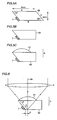
- substrate 20 is cut such that the cut surface is perpendicular to the surface of substrate 20 when viewed in the y direction and angled at 53° relative to the surface of substrate 20 when viewed in the x direction. The reason why the substrate is cut as angled in this way is given later.
- A, B and C surfaces of transparent substrate 62 are processed such that B surface is grinded until the leading edge of magnetic head 7 matches with B surface, A surface is smoothed until it becomes an optical flat, and C surface is also grinded as shown in Fig. 5B.
- plano-convex lens 61 with the refractive index of 1.5 is joined onto A surface of transparent substrate 62.
- resin or the like which has a refractive index approximately equal to those of plano-convex lens 61 and transparent substrate 62 (about 1.5)
- unnecessary reflection or the like can be avoided.
- auxiliary lens 6 into which solid immersion lens 61, 62 and magnetic head 7 are integrated is implemented.
- thermomagnetic recording and reproducing system is employed. Therefore, desirably the interval between the position onto which light beam is emitted on the recording medium and a location where at least the magnetic reproducing head is formed (the location where magnetic recording and reproducing head 7 is formed), i.e. distance d in Fig. 6, should be made small to some extent.
- the angle ⁇ formed by the surface where magnetic recording and reproducing head 7 is formed (C surface) at transparent substrate 62 and the surface which is parallel to recording medium 8 (surfaces A and B: surface which is perpendicular to the direction of an optical axis 9a) is represented by ⁇ ⁇ 90° - ⁇ where ⁇ represents half of the angular aperture of the light beam in transparent substrate 62. (See angle ⁇ , ⁇ in Fig. 6.) Accordingly, optical head 7 is not located in the optical path and distance d can be shortened.
- the magneto-optical head device in this embodiment can thus be reduced in size since the magnetic recording and reproducing head (magnetic head for reproduction and recording) is directly formed at the component of the auxiliary lens.
- the reproducing operation can smoothly be implemented since the position which is irradiated with light beam on the recording medium is located in the dose vicinity of the magnetic reproducing head.
- the magnetic recording and reproducing head is apparently not limited thereto.
- Fig. 7 illustrates an apparatus used for testing recording and reproduction.
- Photodetector 11 may have a plurality of divided regions applied to tracking control and focusing control. In this case, a diffraction grating is placed for generating a plurality of beams.
- Recording medium 8 is rotated by a spindle motor 55, and the rotational direction is perpendicular to the plane of the drawing.
- a stage 56 on which the mirror is mounted, objective lens 5, and auxiliary lens 6 are connected by a spring (gimbal) 57 and auxiliary lens 6 flies over the medium.
- Objective lens 5 and auxiliary lens 6 are fixed to a support pipe 58.
- Stage 56 on which the mirror is mounted is moved in the radius direction of the disk using a shaft 59.
- Tracking is implemented by moving stage 56 having the mirror mounted thereon along shaft 59. Focusing is implemented by moving relay lens 52 in the direction of the arrow B. Distance d between magnetic head 7 and a beam spot shown in Fig. 6 is controlled by moving objective lens 5 in the direction perpendicular to the plane of the drawing.
- Control of focusing and distance d is implemented by preliminary adjusting and fixing the position of objective lens 5 and relay lens 52 prior to recording and reproduction.
- Tracking is implemented by controlling an actuator (not shown) on which stage 56 is mounted such that the reflected light is used to read a track error signal and a beam spot follows a track which is formed on the disk while recording and reproduction are carried out.
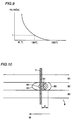
- Fig. 9 illustrates temperature dependency of coercive force Hc of this material
- Coercive force Hc is high at room temperature, decreases as the temperature rises and is equal to 1kOe at approximately 180°C.
- Fig. 10 illustrates the state in which recording and reproduction are carried out as viewed from above disk 8.
- Disk 8 moves in the direction of the arrow M and a beam spot 80 is shown to scan over a track 82.
- Magnetic head has a width extending over adjacent tracks 81 and 83.
- the reference numeral 84 represents an isotherm formed in the recording layer.
- the outermost isotherm represents 100°C
- the middle one represents 180°C
- the innermost one represents 200°C.
- Thermomagnetic recording and reproducing medium 8 has a certain time constant from the time at which laser irradiation occurs until the temperature increases, and further has a certain time constant until the temperature falls to room temperature. Therefore, as illustrated in the drawing, the center of isotherm 84 is located in the downstream in the rotational direction of disk 8 relative to the center of beam spot 80.
- magnetic recording and reproducing head 7 is placed in the downstream in the rotational direction of disk 8, not at beam spot 80.
- the isotherm representing temperature e.g. 180°C
- the positional relation between the isotherm and magnetic head 7 varies depending on the number of revolutions of the disk, temperature characteristics of thermomagnetic recording and reproducing medium 8, the intensity of laser, distance d between beam spot 80 and magnetic head 7, and the like. Accordingly, adjustment may be made by changing any of those parameters.
- distance d between beam spot 80 and magnetic head 7 is adjusted such that the position of the isotherm is located in the upstream in the direction of rotation of disk 8 relative to the position of magnetic head 7.
- the recording density in the direction of tracks can be enhanced to be equivalent to the spot size of the light beam.
- the line density can be enhanced to be equivalent to resolving power determined by the gap width of the magnetic reproducing head.
- the device employed in this embodiment implements the beam spot size of 0.5 ⁇ m by optical constant of the optical system. Further, using a GMR head having a gap of 0.15 ⁇ m as the magnetic reproducing head, a signal of 0.1 ⁇ m mark /0.1 ⁇ m space can be reproduced without crosstalk. Recording and reproduction are implemented using line velocity of 5 m/sec and laser power of 4 mW.
- Distance d shown in Figs. 6 and 10 indicates the distance between the center of beam spot 80 and magnetic head 7.
- the relation between distance d and the amount of reflected light is examined and its result is shown in Figs. 11A and 11B.
- the amount of reflected light is herein measured without placing any medium and thus the amount of light reflected from the end surface (B surface) of auxiliary lens 6 opposite to the medium is measured.
- the amount of reflected light is saturated when d equals to 1 ⁇ m. Therefore, the amount of light at this time is standardized as 1 and the result is shown in the drawing.
- the amount of reflected light is almost 0 when d ⁇ 0, the amount of reflected light gradually increases when d > 0, and the amount of light substantially reaches saturation when d equals to 0.5 ⁇ m. It is thus found that distance d between beam spot 80 and magnetic head 7 may be at least 0.5 ⁇ m.
- the positioning accuracy of 0.5 ⁇ m falls in a range which can correctly be achieved.
- the track density and the line density can be enhanced and both surfaces of the disk can be used as apparent from Fig. 6.
- optical reproduction is possible with the magneto-optical head by detecting information included in the reflected light, which is not described in this embodiment.
- embossed pits are formed on the medium, for example, any difference in the amount of reflected light can be detected by presence/absence of the embossed pits when the thermomagnetic recording and reproducing medium is unavailable.
- the magneto-optical head device in this embodiment is provided with a function of reading magnetic information by the magnetic reproducing head and a function of reading optical information by the reflected light.
- magnetic head 7 is a composite head formed by attaching an inductive head for recording and a GMR head for reproduction together.
- a magnetic recording head 71 and a magnetic reproducing head 72 are separated as shown in Figs. 13A - 14D.
- a cylindrical hole with a diameter of 3 mm is made from A surface to B surface of a chip produced by fabricating magnetic reproducing head 72 on a transparent substrate 61 and cutting the substrate.
- B surface a groove which is 0.5 mm in depth and 3 mm in width is formed.
- Fig. 13B illustrates the cylindrical hole and the groove as viewed from B surface.
- a solid cylindrical chip (magnetic recording head 71) which is 3 mm in diameter as illustrated in Fig. 13C is fabricated.
- the chip of the solid cylindrical shape is formed of glass with a refractive index of 1.5 and thus the refractive index is equal to that of substrate 61.
- a coil 71a as shown in Fig. 13D is formed through a thin film process and glass coating 71b is applied thereto.
- the cross section of the solid cylindrical chip is shown in Fig. 13E.
- the coating is implemented by applying glass with refractive index of 1.5 to approximately 50 ⁇ m.
- a terminal 71c of coil 71a is exposed on the side surface of the solid cylindrical chip.
- Such a solid cylindrical chip is inserted into the cylindrical hole of transparent substrate 61.
- FIG. 14A This state is shown in Fig. 14A. After that, A, B and C surfaces are grinded as done in the first embodiment. This state is shown in Fig. 14B as viewed from B surface. Wire passes though the groove formed in B surface to enable electric current to be supplied to coil 71a.
- auxiliary lens 6 In the magneto-optical head device using such auxiliary lens 6, in recording, light is condensed on the center of the coil through an optical path 101 as shown in Fig. 14D to increase the temperature of a recording layer of the medium.
- the inner diameter of the coil is about 50 ⁇ m and the outer diameter thereof is about 100 ⁇ m.
- the coil is placed near the height of the focus of the beam and the inner diameter is sufficiently large relative to the beam spot. Therefore, the light is not blocked by the coil.
- Optical path 100 or 101 is employed depending on recording and reproduction. Switching of the optical path is possible by moving the position of the relay lens in Fig. 7 in the direction perpendicular to the plane of the drawing. The switching of the optical path causes a slight change in the angle of light beam incident on plano-convex lens 62. However, this change is minor, If necessary, the angle of incidence may be corrected when the optical path is switched.
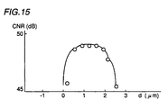
- a signal with 0.2 ⁇ m mark /0.2 ⁇ m space is recorded with linear velocity of 5 m/sec and laser power of 6 mW and a relation between CNR and d when the signal is reproduced with the same line velocity and laser power of 4 mW is illustrated in Fig. 15.
- the manufacturing process becomes complicated by separately forming magnetic reproducing head 72 and magnetic recording head 71 compared with the first embodiment in which those heads are integrally fabricated by the thin film process.
- the features of respective heads can be realized to their maximum and accordingly a magnetic head of a high performance can be implemented.
- the switching of the optical path as described above allows magnetic reproducing head 72 and an optical reproducing beam as well as magnetic recording head 71 and optical recording beam to be closely arranged easily. If magnetic reproducing head 72 and magnetic recording head 71 are separated, the arrangement as described above may not be employed.
- both of the track density and the line density can be enhanced.
- the magneto-optical head device is constructed to include the magnetic reproducing head and the magnetic recording head such that both of recording and reproduction can be carried out.
- the magneto-optical head device may include only the magnetic reproducing head.
- the function is limited to reproduction only.
- information can be reproduced from not only an ordinary optical recording medium but from a thermomagnetic medium.
- only a magnetic recording head may be included. In this case, although reproduction from the thermomagnetic recording medium is impossible, reproduction from another optical recording medium, and recording on an optical recording medium including the thermomagnetic recording medium is possible.
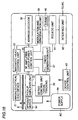
- Fig. 16 is a schematic block diagram illustrating a structure of a recording and reproducing device in the third embodiment of the present invention.
- the recording and reproducing device includes a magneto-optical head device 31 as illustrated in the first and second embodiments, a magnetic head control unit 32 which controls a magnetic head 7 in magneto-optical head device 31, a pickup amplifier unit 33 which amplifies information such as a synchronous signal read by magneto-optical head device 31, a spindle motor 34 which rotates a thermomagnetic recording medium 8 at predetermined number of revolutions, an RF (Radio Frequency) amplifier/laser power control unit 35 which controls amplification of high frequency of the synchronous signal or the like amplified by pickup amplifier unit 33 as well as output of a laser diode 1 in magneto-optical head device 31, a servo control unit 36 which controls focusing servo, tracking servo and the like, a PLL (Phase Locked Loop) ⁇ timing generation unit 37 which generates various timing signals for generation of
- thermomagnetic recording medium 8 When data is to be recorded on thermomagnetic recording medium 8, the data is supplied via interface unit 42, an error correction/detection code is applied thereto by ECC/EDC unit 41, and the data is temporarily stored in D-RAM 40.
- Servo control unit 36 performs tracking of magneto-optical head device 31 to move magneto-optical head device 31 to a track on which the data is to be recorded.
- Address decoder 38 extracts a predetermined address from the data read by magneto-optical head device 31.
- modulation and demodulation unit 39 reads written data from D-RAM 40, modulates the data and thereafter supplies the modulated data to magnetic head control unit 32.
- servo control unit 36 When data is to be reproduced from thermomagnetic recording medium 8, servo control unit 36 performs tracking of magneto-optical head device 31 to move magneto-optical head device 31 to a track from which data is to be read.
- RF amplifier/laser power control unit 35 controls laser diode 1 within magneto-optical head device 31 to direct a light beam onto thermomagnetic recording medium 8
- magnetic head control unit 32 controls magneto-optical head device 31 to read data from thermomagnetic recording medium 8.
- Address decoder 38 extracts a predetermined address from the data read by magneto-optical head device 31.
- modulation and demodulation unit 39 demodulates the data read by magneto-optical head device 31, and temporarily stores it in D-RAM 40.
- ECC/EDC unit 41 reads the data stored in D-RAM 40, performs error detection and error correction, and thereafter supplies the data to interface unit 42.
- Interface unit 42 supplies the data to a personal computer or the like connected thereto.
Landscapes
- Engineering & Computer Science (AREA)
- Physics & Mathematics (AREA)
- Chemical & Material Sciences (AREA)
- Nanotechnology (AREA)
- Optics & Photonics (AREA)
- Crystallography & Structural Chemistry (AREA)
- Mathematical Physics (AREA)
- Theoretical Computer Science (AREA)
- Manufacturing & Machinery (AREA)
- Optical Head (AREA)
- Recording Or Reproducing By Magnetic Means (AREA)
Applications Claiming Priority (2)
| Application Number | Priority Date | Filing Date | Title |
|---|---|---|---|
| JP29432598 | 1998-10-16 | ||
| JP29432598A JP3442296B2 (ja) | 1998-10-16 | 1998-10-16 | 光磁気ヘッド装置及び記録再生装置 |
Publications (2)
| Publication Number | Publication Date |
|---|---|
| EP0994466A2 true EP0994466A2 (de) | 2000-04-19 |
| EP0994466A3 EP0994466A3 (de) | 2001-07-11 |
Family
ID=17806249
Family Applications (1)
| Application Number | Title | Priority Date | Filing Date |
|---|---|---|---|
| EP99120477A Withdrawn EP0994466A3 (de) | 1998-10-16 | 1999-10-14 | Magneto-optische Kopfvorrichtung mit integrierter Hilfslinse und magneto-optischer Wiedergabekopf und die magneto-optische Kopfvorrichtung benutzende Aufzeichnungs - und Wiedergabevorrichtung |
Country Status (4)
| Country | Link |
|---|---|
| US (1) | US6556517B1 (de) |
| EP (1) | EP0994466A3 (de) |
| JP (1) | JP3442296B2 (de) |
| KR (1) | KR100377980B1 (de) |
Cited By (4)
| Publication number | Priority date | Publication date | Assignee | Title |
|---|---|---|---|---|
| WO2001091114A1 (en) * | 2000-05-24 | 2001-11-29 | Koninklijke Philips Electronics N.V. | A method of thermally-assisted data recording and a recording apparatus |
| WO2002013188A1 (en) * | 2000-08-09 | 2002-02-14 | Koninklijke Philips Electronics N.V. | Method of manufacturing a magnetic head having a planar coil |
| WO2004008441A3 (en) * | 2002-07-10 | 2004-04-22 | Koninkl Philips Electronics Nv | Optical recording and reading system, optical data storage medium and use of such medium |
| EP1327979B1 (de) * | 2002-01-11 | 2006-03-29 | Fuji Photo Film Co., Ltd. | Optisches Informationsaufzeichnungsmedium |
Families Citing this family (10)
| Publication number | Priority date | Publication date | Assignee | Title |
|---|---|---|---|---|
| US20010040841A1 (en) * | 1999-12-15 | 2001-11-15 | Shieh Han-Ping David | Recording method and medium for optical near-field writing and magnetic flux reading |
| JP4354075B2 (ja) * | 2000-03-09 | 2009-10-28 | シャープ株式会社 | 複合磁気ヘッド装置、それを用いた情報記録再生装置および記録媒体 |
| JP4584417B2 (ja) * | 2000-06-14 | 2010-11-24 | シャープ株式会社 | 磁気情報再生用プローブ及びそのプローブの製造方法 |
| US6807131B1 (en) * | 2000-12-27 | 2004-10-19 | Research Investment Network, Inc. | Near-field hybrid magnetic-optical head system |
| US7177550B1 (en) * | 2001-01-24 | 2007-02-13 | Ball Aerospace & Technologies Corp. | On-axis laser receiver wavelength demultiplexer with integral immersion lensed detectors |
| KR100417404B1 (ko) * | 2001-04-25 | 2004-02-05 | 엘지전자 주식회사 | 근접장 광기록시스템 |
| KR100429974B1 (ko) * | 2001-10-18 | 2004-05-03 | 엘지전자 주식회사 | 근접장 광기록재생장치, 그 제조방법 |
| KR100438574B1 (ko) * | 2001-11-27 | 2004-07-02 | 엘지전자 주식회사 | 근접장 광기록재생장치 |
| JP2006286119A (ja) * | 2005-04-01 | 2006-10-19 | Sony Corp | 光アシスト型磁気ヘッド、磁気記録装置、および光アシスト型磁気ヘッドの製造方法 |
| KR101104636B1 (ko) | 2010-05-04 | 2012-01-12 | 연세대학교 산학협력단 | 열보조 자기기록의 마이크로 레이저 모듈과 이의 자세 제어를 통한 광량 제어 시스템 및 방법 |
Family Cites Families (2)
| Publication number | Priority date | Publication date | Assignee | Title |
|---|---|---|---|---|
| JPH10162444A (ja) * | 1996-07-25 | 1998-06-19 | Hitachi Maxell Ltd | 光磁気記録媒体と記録再生方法、及び記録再生装置 |
| EP0899721A4 (de) * | 1997-02-17 | 2002-03-13 | Seiko Epson Corp | Magnetaufzeichnungsmethode |
-
1998
- 1998-10-16 JP JP29432598A patent/JP3442296B2/ja not_active Expired - Fee Related
-
1999
- 1999-10-14 EP EP99120477A patent/EP0994466A3/de not_active Withdrawn
- 1999-10-15 KR KR10-1999-0044664A patent/KR100377980B1/ko not_active Expired - Fee Related
- 1999-10-15 US US09/419,232 patent/US6556517B1/en not_active Expired - Fee Related
Cited By (4)
| Publication number | Priority date | Publication date | Assignee | Title |
|---|---|---|---|---|
| WO2001091114A1 (en) * | 2000-05-24 | 2001-11-29 | Koninklijke Philips Electronics N.V. | A method of thermally-assisted data recording and a recording apparatus |
| WO2002013188A1 (en) * | 2000-08-09 | 2002-02-14 | Koninklijke Philips Electronics N.V. | Method of manufacturing a magnetic head having a planar coil |
| EP1327979B1 (de) * | 2002-01-11 | 2006-03-29 | Fuji Photo Film Co., Ltd. | Optisches Informationsaufzeichnungsmedium |
| WO2004008441A3 (en) * | 2002-07-10 | 2004-04-22 | Koninkl Philips Electronics Nv | Optical recording and reading system, optical data storage medium and use of such medium |
Also Published As
| Publication number | Publication date |
|---|---|
| US6556517B1 (en) | 2003-04-29 |
| EP0994466A3 (de) | 2001-07-11 |
| JP3442296B2 (ja) | 2003-09-02 |
| JP2000123303A (ja) | 2000-04-28 |
| KR100377980B1 (ko) | 2003-03-29 |
| KR20000029090A (ko) | 2000-05-25 |
Similar Documents
| Publication | Publication Date | Title |
|---|---|---|
| US4985881A (en) | Record carrier for a magneto-optical disc memory having guide grooves of a plurality of tracks disposed with a predetermined relation to light spot diameter | |
| JP2001273650A (ja) | 光ピックアップ装置 | |
| US6556517B1 (en) | Magneto-optical head device having integrated auxiliary lens and magnetic reproducing head and recording and reproducing device using magneto-optical head device | |
| US4549287A (en) | System for recording and playing back information with magneto-optical disk memory using record and readout light beams of different wavelengths | |
| JP4038336B2 (ja) | 情報記録再生方法 | |
| EP1811511A2 (de) | Optisches Aufzeichnungs-/Wiedergabegerät, optischer Lesekopf und Verfahren zur Spurfehlererkennung | |
| JP3857235B2 (ja) | 光学装置及び光記憶装置 | |
| EP0614176B1 (de) | Wiedergabeverfahren und -gerät für optische Platte | |
| US6901036B2 (en) | Method and apparatus for reproducing an optical signal | |
| US6115330A (en) | Optical information storage unit for recording and/or reproducing information on both the lands and the grooves of an optical medium | |
| EP0393652B1 (de) | Magnetooptische Aufzeichnungs- und Wiedergabeverfahren, magnetooptische Speichervorrichtung | |
| US5199024A (en) | Optical data storage medium having embedded tracking information | |
| JPS5877046A (ja) | 磁気光学ヘツド | |
| JP2935554B2 (ja) | 光ヘッド | |
| JP2792267B2 (ja) | 光ヘッド | |
| JP3498139B2 (ja) | 光記録媒体、光記録再生装置、および光記録再生方法 | |
| US5490129A (en) | Optical head and optical information reading apparatus | |
| JP2000132880A (ja) | 情報再生素子及びそれを備える情報記録/再生ヘッド並びに情報再生方法 | |
| JPS62185268A (ja) | 光磁気メモリ−デイスク光照射方法 | |
| JP2002032941A (ja) | ヘッド位置調整方法及び記録再生装置 | |
| JP2000149304A (ja) | 光ディスク装置と光学ピックアップ及びこれに使用される半球レンズとその製造方法 | |
| JP2000339769A (ja) | 情報記録媒体および情報記録再生装置 | |
| JP2001035030A (ja) | 光学的情報記録再生装置及び光ヘッド並びに光学的記録媒体 | |
| JPS62185251A (ja) | 光メモリ−デイスク光照射方法 | |
| JPS60103539A (ja) | 光磁気記録再生装置 |
Legal Events
| Date | Code | Title | Description |
|---|---|---|---|
| PUAI | Public reference made under article 153(3) epc to a published international application that has entered the european phase |
Free format text: ORIGINAL CODE: 0009012 |
|
| AK | Designated contracting states |
Kind code of ref document: A2 Designated state(s): DE GB |
|
| AX | Request for extension of the european patent |
Free format text: AL;LT;LV;MK;RO;SI |
|
| PUAL | Search report despatched |
Free format text: ORIGINAL CODE: 0009013 |
|
| AK | Designated contracting states |
Kind code of ref document: A3 Designated state(s): AT BE CH CY DE DK ES FI FR GB GR IE IT LI LU MC NL PT SE |
|
| AX | Request for extension of the european patent |
Free format text: AL;LT;LV;MK;RO;SI |
|
| RIC1 | Information provided on ipc code assigned before grant |
Free format text: 7G 11B 5/00 A, 7G 11B 7/10 B, 7G 11B 11/105 B, 7G 11B 13/00 B, 7G 11B 5/17 B |
|
| 17P | Request for examination filed |
Effective date: 20010924 |
|
| AKX | Designation fees paid |
Free format text: DE GB |
|
| 17Q | First examination report despatched |
Effective date: 20050208 |
|
| STAA | Information on the status of an ep patent application or granted ep patent |
Free format text: STATUS: THE APPLICATION IS DEEMED TO BE WITHDRAWN |
|
| 18D | Application deemed to be withdrawn |
Effective date: 20050621 |