EP0994540A2 - Automatisches Drahtschneide- und Anschliessgerät - Google Patents
Automatisches Drahtschneide- und Anschliessgerät Download PDFInfo
- Publication number
- EP0994540A2 EP0994540A2 EP99119987A EP99119987A EP0994540A2 EP 0994540 A2 EP0994540 A2 EP 0994540A2 EP 99119987 A EP99119987 A EP 99119987A EP 99119987 A EP99119987 A EP 99119987A EP 0994540 A2 EP0994540 A2 EP 0994540A2
- Authority
- EP
- European Patent Office
- Prior art keywords
- wire
- transporter
- cutting
- terminal
- clamp
- Prior art date
- Legal status (The legal status is an assumption and is not a legal conclusion. Google has not performed a legal analysis and makes no representation as to the accuracy of the status listed.)
- Withdrawn
Links
Images


Classifications
-
- H—ELECTRICITY
- H01—ELECTRIC ELEMENTS
- H01R—ELECTRICALLY-CONDUCTIVE CONNECTIONS; STRUCTURAL ASSOCIATIONS OF A PLURALITY OF MUTUALLY-INSULATED ELECTRICAL CONNECTING ELEMENTS; COUPLING DEVICES; CURRENT COLLECTORS
- H01R43/00—Apparatus or processes specially adapted for manufacturing, assembling, maintaining, or repairing of line connectors or current collectors or for joining electric conductors
- H01R43/04—Apparatus or processes specially adapted for manufacturing, assembling, maintaining, or repairing of line connectors or current collectors or for joining electric conductors for forming connections by deformation, e.g. crimping tool
- H01R43/048—Crimping apparatus or processes
- H01R43/052—Crimping apparatus or processes with wire-feeding mechanism
-
- H—ELECTRICITY
- H01—ELECTRIC ELEMENTS
- H01R—ELECTRICALLY-CONDUCTIVE CONNECTIONS; STRUCTURAL ASSOCIATIONS OF A PLURALITY OF MUTUALLY-INSULATED ELECTRICAL CONNECTING ELEMENTS; COUPLING DEVICES; CURRENT COLLECTORS
- H01R43/00—Apparatus or processes specially adapted for manufacturing, assembling, maintaining, or repairing of line connectors or current collectors or for joining electric conductors
- H01R43/04—Apparatus or processes specially adapted for manufacturing, assembling, maintaining, or repairing of line connectors or current collectors or for joining electric conductors for forming connections by deformation, e.g. crimping tool
- H01R43/048—Crimping apparatus or processes
- H01R43/05—Crimping apparatus or processes with wire-insulation stripping
-
- Y—GENERAL TAGGING OF NEW TECHNOLOGICAL DEVELOPMENTS; GENERAL TAGGING OF CROSS-SECTIONAL TECHNOLOGIES SPANNING OVER SEVERAL SECTIONS OF THE IPC; TECHNICAL SUBJECTS COVERED BY FORMER USPC CROSS-REFERENCE ART COLLECTIONS [XRACs] AND DIGESTS
- Y10—TECHNICAL SUBJECTS COVERED BY FORMER USPC
- Y10T—TECHNICAL SUBJECTS COVERED BY FORMER US CLASSIFICATION
- Y10T29/00—Metal working
- Y10T29/51—Plural diverse manufacturing apparatus including means for metal shaping or assembling
- Y10T29/5136—Separate tool stations for selective or successive operation on work
- Y10T29/5137—Separate tool stations for selective or successive operation on work including assembling or disassembling station
- Y10T29/5139—Separate tool stations for selective or successive operation on work including assembling or disassembling station and means to sever work prior to disassembling
- Y10T29/514—Separate tool stations for selective or successive operation on work including assembling or disassembling station and means to sever work prior to disassembling comprising means to strip insulation from wire
-
- Y—GENERAL TAGGING OF NEW TECHNOLOGICAL DEVELOPMENTS; GENERAL TAGGING OF CROSS-SECTIONAL TECHNOLOGIES SPANNING OVER SEVERAL SECTIONS OF THE IPC; TECHNICAL SUBJECTS COVERED BY FORMER USPC CROSS-REFERENCE ART COLLECTIONS [XRACs] AND DIGESTS
- Y10—TECHNICAL SUBJECTS COVERED BY FORMER USPC
- Y10T—TECHNICAL SUBJECTS COVERED BY FORMER US CLASSIFICATION
- Y10T29/00—Metal working
- Y10T29/51—Plural diverse manufacturing apparatus including means for metal shaping or assembling
- Y10T29/5193—Electrical connector or terminal
-
- Y—GENERAL TAGGING OF NEW TECHNOLOGICAL DEVELOPMENTS; GENERAL TAGGING OF CROSS-SECTIONAL TECHNOLOGIES SPANNING OVER SEVERAL SECTIONS OF THE IPC; TECHNICAL SUBJECTS COVERED BY FORMER USPC CROSS-REFERENCE ART COLLECTIONS [XRACs] AND DIGESTS
- Y10—TECHNICAL SUBJECTS COVERED BY FORMER USPC
- Y10T—TECHNICAL SUBJECTS COVERED BY FORMER US CLASSIFICATION
- Y10T29/00—Metal working
- Y10T29/53—Means to assemble or disassemble
- Y10T29/5313—Means to assemble electrical device
- Y10T29/532—Conductor
- Y10T29/53209—Terminal or connector
- Y10T29/53213—Assembled to wire-type conductor
Definitions
- the present invention relates to an automatic wire cutting and terminating apparatus of a type that cuts an insulated electric wire, and strips a length of insulation from a respective cut end of the electric wire or a cur piece thereof, terminating the stripped end by applying a crimp-on (or solder-less) terminal for use, for example, in a wire harness of a vehicular electrical system.
- Fig. 9 is a plan of the both-end terminating apparatus, and Fig. 10, a front view of an essential part of the apparatus.
- a supply station 3 has a large number of wire-feeding tubes 3a, on a base 2.
- the supply station 3 is provided so that it can freely move in the direction indicated by the arrow e.
- a rotating arm 4 is provided on the ejection side of the supply station 3, this arm having a clamping means (not shown) for clamping an electrical wire W that is supplied from the supply station 3.
- the rotating arm 4 can freely swing (rotate) left and right with respect to the base 2, about the axis 5.
- a head 4a of the arm 4 can be positioned at a reference position H, a maximum-swing work position J, which is at the maximum angle from the reference position H, and at an intermediate work position I, which is between the above-noted reference and maximum-angle positions.
- the head 4a of the rotating arm 4 is configured so as to be opposite the wire cutter 6A when in the reference position H, opposite the wire insulation stripper 6B when in the intermediate position I, and opposite the terminal-crimping part when at the maximum-angle work position J.
- a first transporter 7 is provided on the base 2, this first transporter 7 being freely movable in the directions indicated by the arrows m and n in Fig. 9.
- Four clamps, 7a through 7d are provided at a uniform mutual spacing on the first transporter 7, the clamp 7a moving being the reference position H and the first work position K, the claim 7b moving being the first work position K and a second work position L, the clamp 7c moving between the second work position K and a third work position M, and the clamp 7d moving between the third work position M and a fourth work position N.
- a moving cylinder 7S is moved to the reference position H along a cylinder rod 7R, the first clamp 7a of the first transporter 7 is brought into opposition with the wire cutter 6A.
- a second transporter 8 is also provided at the first work position K of the first transporter 7, this being provided so as to enable free movement thereof in the direction of the arrow p.
- the second transporter 8 has a clamp 8a, which by moving a clamped wire W in the direction of the arrow p, enables the movement of the wire W to a position opposite an insulation-stripping part 6D.
- a third transporter 9 is provided at the second work position L of the first transporter 7, this being freely movable in the direction of the arrow q.
- the third transporter 9 has a clamp 9a which moves in the direction of the arrow q, so as to move a clamped wire W to a position opposite a terminal-crimping part 6E.
- a clamp 6F is provided at the third work position M and a fourth clamp G is provided at the fourth work position N of the first transporter 7.
- a wire W is supplied by the supply station 3 to the rotating arm 4, the supplied wire W being clamped by a clamping means (not shown), and the end of the wire W being set in a position so that it protrudes from the head 4a of the rotating arm 4.
- the wire W that protrudes from the head 4a of the rotating arm 4 is cut by the wire cutter 6A, and the rotating arm 4 rotates from the reference position H to the intermediate work position I.
- the insulation covering of the cut end of the wire W is stripped by the wire insulation stripper 6B, and the rotating arm rotates from the intermediate work position I to the maximum-angle work position J.
- a terminal is crimped onto the conductor of the wire W by the terminal crimper 6C, at which point the rotating arm 4 returns from the maximum-angle work position J to the reference position H, thereby completing the process of terminating one end of the wire W.
- the first transporter 7 moves in the direction of the arrow m, the first clamp 7a being positioned at the reference position H, and a prescribed amount of the wire W being pulled out from the head 4a of the rotating arm 4.
- This extended wire W is clamped by the first clamp 7a of the first transporter 7, the first clamp 7 moving in the direction of arrow n, so that the first clamp 7a is moved to the first work position K.
- the clamp 8a of the second transporter 8 re-clamps the wire W and moves in the direction of the arrow p, so that the wire W is moved to the region of the insulation stripper 6D.
- the insulation stripper 6D strips the insulation covering from the other end of the wire W, after which the second transporter 8 returns to its original position.
- the second clamp 7b of the first transporter 7 moves to the first work position K, and the second clamp 7b re-clamps the wire W.
- the first transporter 7 moves in the direction of the arrow n, so that the second clamp 7b is moved to the second work position L.
- the clamp 9a of the third transporter 9 re-clamps the wire W, and moves in the direction of the arrow q, so that the wire W is moved to the region of the terminal crimper 6E.
- the terminal crimper 6E crimps a terminal on to the other end of the wire W, after which the third transporter 9 returns to its original position.
- the third clamp 7c of the first transporter 7 moves to the second work position, and re-clamps the wire W.
- the first transporter 7 moves in the direction of the arrow n, so that the third clamp 7c moves to the third work position M.
- the clamp 6F re-clamps the wire W and the first transporter 7 moves so as to move the wire W to the fourth work position N, the wire ejector 6G ejecting the wire W, which completes the process of terminating the other end of the wire W.
- the configuration of the above-described double-end crimping apparatus 1 is such that, when a terminal is crimped onto the first end of the wire W and the head 4a of the rotating arm 4 returns from the maximum-angle work position J to the reference position H, the first clamp 7a of the first transporter 7 moving to the reference position H (the position opposite to the wire cutter 6A as shown in Fig. 9), a prescribed amount of the wire W is pulled out from the head 4a of the rotating arm 4, this extended part of the wire W being clamped by the first clamp 7a and transported to the first work position (the position which at which the other end of the wire W is terminated).
- an object of the present invention to solve the above-noted drawbacks in the related art, by providing an automatic wire cutting and terminating apparatus wherein, the wire can be securely grabbed simultaneously the return of a wire guide of a wire transporter from a terminal crimper to a cutting and stripping unit, thereby enabling the elimination of failed products and the reduction of the production time.
- a first aspect of the present invention provides an automatic wire cutting and terminating apparatus comprising a first terminating section for crimping a terminal on a stripped end of a length of insulated electric wire set in a first termination position, a wire transporter for transporting the length of insulated electric wire with the terminal crimped thereon from the first termination position in a first direction to a second termination position, a second terminating section for terminating another end of the length of insulated electric wire received at the second termination position, and a clamp mechanism for clamping part of the length of insulated electric wire at the second termination position, the clamp mechanism comprising a pair of clamping members movable relative to each other in a second direction crossing the first direction for positioning the part of the length of insulated electric wire.
- the length of insulated electric wire can be held in position in an ensured and facilitated manner.
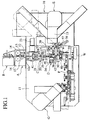
- Fig. 1 shows in plan an entirety of an automatic wire cutting and terminating apparatus 10 according to an embodiment of the present invention.
- the wire cutting and terminating apparatus 10 has a base 11 of which a front side leftwardly and rightwardly extends at the bottom side of the figure and a rear side extends at the top side of the figure.
- the apparatus 10 comprises a wire-measuring unit A located at the rear edge at substantially the center of the base 11 for measuring out the wire W by a prescribed length, a wire correction unit B mounted to the rear end of the wire measuring unit A for correcting bends and kinks in the wire A and feeding the wire W to the wire measuring unit A, a wire rotating unit C mounted at the rear side of the approximate center on the base 11 for cutting the wire W, a cutting and stripping unit D mounted substantially in the center of the base 11 for cutting the wire W and stripping the insulation covering from the cut end thereof, a terminal-crimping unit mounted on one side of the base 11 for crimping a terminal T onto the stripped end Wa of the wire W that was cut and stripped by the cutting and stripping unit D so as to make a connection thereto, a wire transporting unit F mounted in the approximate center of the other side on the base 11 for transporting the cut wire W after a terminal T is crimped onto the end thereof, and a terminal-crimping unit G mounted to the other side
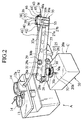
- the wire rotating unit C of the automatic wire cutting and terminating apparatus 10 has a speed reduction case 20 mounted to the base 11 and rotatably supporting at its center a rotating shaft 21, a servomotor (drive source) 23 mounted to one wall 20a of the speed reduction case 20 which has at the end of its rotating shaft 23a a worm gear 24, which meshes with a worm wheel 22 that is fixed to the bottom end 21a of the rotating shaft 21, and a wire transporter 25 fixed to an upper edge 21b of the rotating shaft 21 that protrudes from the center of the speed reduction case 20 to the outside thereof, this wire transporter 25 reciprocally moving the wire W between the cutting and stripping unit D and the terminal-crimping unit E for one end of the wire W.
- a servomotor (drive source) 23 mounted to one wall 20a of the speed reduction case 20 which has at the end of its rotating shaft 23a a worm gear 24, which meshes with a worm wheel 22 that is fixed to the bottom end 21a of the rotating shaft 21, and a wire transporter 25 fixed
- the wire transporter 25 is formed by an arm holder (base end) 26, having a squared-cup shape when viewed from the front and fixed to the upper end 21b of the rotating shaft 21, supported via the walls 26a extending on both sides of the base end of the arm holder 26 so as to swing freely to the left and right.
- a bolt 29 is screwed into the front side of the arm holder 26.
- the rotating arm 27 passes through the shank of the bolt 29 (not shown), a compression coil spring (resilient impelling member, not shown) inserted around the shank acting to constantly impel the upper end 27a of the rotating arm 27 upward. The action of the compression coil spring in impelling the rotating arm 27 upward is restricted by the head 29a of the bolt 29.
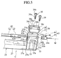
- an air cylinder (drive cylinder) 35 and a holding member 37 of a holder 36 are fixed to a cutout 27b at the lower side of the end 27a of the rotating arm 27, via a linking plate 33 and a plurality of bolts 34 (Fig. 4).
- This holder 36 has a hollow 37a that extends in the wire feeding direction, and that houses the far end of a guide tube 40 and the base end side of a nozzle 43, to be described below, and a cover 38, which is mounted using three bolts (tightening means) 39 so that it covers the hollow 37a between the walls 37b and 37c on either side of the holding member 37.
- the height of one of the walls 37b o the two side walls 37b and 37c of the holding member 37 is formed so as to be lower than the height of the other side wall 37c.
- threaded holes 37d On the center part of the top surface of the side wall 37b and both sides of the top surface of the other side wall 37c are formed threaded holes 37d, into which the bolts 39 are screwed.
- threaded holes 37d On both sides of thicker part 38a of the cover 38 are formed through holes 38c, through which the shank 39a and head 39b of the bolts 39 pass, and in the center part of the thinner part 38b of the cover 38 is formed a through hole 38d, through which the shank 39a of a bolt 39 passes.
- the guide tube 40 through which the wire W is passed and which guides the wire W in the wire feeding direction is made up of a tube 41 of a soft, transparent synthetic resin, which extends from the cylinder part 12a of a bracket 12 of the wire measuring unit A, and a tube holder 42, which is substantially cylindrical and which communicates with the end of the tube 41.
- a cutout 42b On the lower side of the end 42a of this tube holder 42 is formed a cutout 42b (see Fig. 5).
- a rectangular aperture 37e is formed in the center of the hollow 37a of the holding member 37 (at a position that is opposite the cutout 42b of the holder tube 42 when it is housed in the hollow 37a), and inside this aperture 37e, a pusher 35b which is integrally formed together with the top end of a piston rod 35a of the air cylinder 35 is can be driven forward and back.
- the wire W while being measured out by a pair of measuring rollers 13 of the wire measuring unit A, it successively fed into the tube 41.
- the nozzle (wire guide) 43 that communicates with the end 42a of the tube holder 42 is formed by a cylindrical metal nozzle body 44 that is substantially the same diameter as the tube holder 42, and a flexible tube 45, which is formed by a tightly wound coil spring or the like that is fixed, via a bolt 46, to the inside of the cylindrical protrusion 44a of the nozzle 44.
- the end 42a of the cube holder 42 of the guide tube 40 and the nozzle body 44 of the nozzle 43 are communicate substantially at the center of the inside of the hollow 37a.
- the guide tube 40 and the nozzle 43 are selected to suit the type and size of wire W. As shown in Fig. 1 and Fig.
- the cutting and stripping unit D has a pair of lower and upper moving members 50 that cut and strip the wire W of its insulation covering, and a clamping mechanism 60, which grabs one end of the wire W when it is being cut and stripped.
- a cutting blade 51 protrudes from the center of the opposing surfaces of the moving members 50, and on either side thereof a stripping blade 52 protrudes.
- a servomotor (not shown) turns a screw 54 so as to move the moving members 50 up and down so that they approach each other or moved away from each other, and a screw 56 that is turned by servomotor 55 imparts forward and reverse movement.
- the stage 53 onto which the clamping mechanism 60 is placed is movable forward and in reverse by a screw 59 that is turned by a servomotor 58.
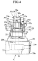
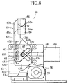
- the clamping mechanism 60 is formed by a first support 63, which is supported to the front surface (single surface) of the base 61 mounted to the stage 53, via a pair of bearings 62 to enable sliding upward and downward, this first support 63 serving also as a stopper for positioning a first end of the wire W, an upper clamp 64 that is fixed to the upper part 63a of the first support 63 and which grabs the wire W in the center of a downward-facing V surface 64a, a second support 65, which is supported by the support 63 via the above-noted pair of bearings 62 to enable sliding upward and downward, and which has a height that is lower than the support 63, a lower clamp 66 that is fixed to the top part 65a of the second support 65, and which grabs the wire W in the center part between the upward-facing V-shaped surface 66a and the downward-facing V-shaped surface 64a of the upper clamp, and an air cylinder (drive source) 69 that has a bearing (cam
- the inclined cams 63c and 65c have a groove holes with inclinations in opposite directions, a bearing 67 that serves as a cam follower that is rotatably supported at the end of the piston rod 68 of the air cylinder 69 being inserted and engaging in the inclined cams 63c and 65c.
- the bearing 67 moves, the result being that the upper and lower clamps 64 and 65, via the inclined cams 63c and 65c of the supports 63 and 65, mode up and down so as to come together or move apart.
- On each of the wider the wide lower parts 63b and 65b of the supports 63 and 65 is formed a pair of vertically elongated holes 63d and 65d.
- the bearings 62 which are rotatably supported on the front surface 61a of the base 61, are inserted into and engage with the inside the vertically elongated hole pairs 63d and 65d. By doing this, the supports 63 and 65 slide in directions that bring them towards or away from each other.
- the piston rod 68 which is moved forward and in reverse by the air cylinder 69, is housed with a hollow 61b formed in the front surface 61a of the base 61, and the bearing 67 protrudes at the front surface 61a.
- the reference numeral 15 in Fig. 3 denotes a terminal crimper of the terminal crimping unit E
- 16 is a stripping inspection unit
- 17 is a terminal crimping inspection unit
- 18 is an intermediate work unit for soldering or the like.
- the reference numerals 35c and 35d denote the air supply ports for the air cylinder 35, by the switching of which the pusher 35c is moved upward and downward.
- a hexagonal hole is formed in the head of each of the bolts 34 and 39, a hexagonal wrench (not shown) or such tool being used to loosen these bolts.
- the wire W is feed into the tube 41 of the guide tube 40 of the transporter 25, via the pair of feed rollers 14 of the wire correction unit B and the wire measuring unit A, so that it is fed outside the end (flexible tube 45) of the nozzle 43.
- the condition in which the wire W is fed by a prescribed amount beyond the end of the nozzle 43 is held in place by the pusher 35b of the piston rod 35a of the air cylinder 35 at the lower end of the wire transporter 25.
- the wire W which is held in place at prescribed intervals by pusher 35b of the piston rod 35a of the air cylinder 35 of at the lower end of the wire transporter and by the upper and lower supports 64 and 66 of the clamping mechanism, is cut by the pair of moving members 50 of the cutting and stripping unit D and the clamping mechanism 60 and, as shown in Fig. 6D and Fig. 6E, the insulation covering material Wc at each cur end of the wire W is stripped away.
- the rotating shaft 21 is turned in the counterclockwise direction by the action of the servomotor 23, the worm gear 24, and the worm wheel 22, so that the nozzle 43 side of the wire transporter 25 is turned, 45 degrees for example, to the terminal-crimping unit E for the first end of the wire, the nozzle 43 of the wire transporter 25 being stopped at the intermediate work position Q for soldering or the like.
- the intermediate work position Q after performing work such as soldering at the covering material Wc at the first end Qa of the first wire W by means of an intermediate work unit, the nozzle 43 end of the wire transporter 25 is further turned, 45 degrees for example, the nozzle 43 of the wire transporter 25 being stopped at the terminal-crimping position R.
- a terminal T is crimped onto the end Wa on the first end of the wire W.
- the rotating arm 27 of the wire transporter 25 is rotated so as to return the nozzle 43 from the terminal-crimping unit E to the original reference position P, at which point the first end of the first wire W is fed out by a prescribed amount by the wire correction unit B and the pair of rollers 14 of the wire measuring unit A, this first end being cut by the cutting and stripping unit D and the insulation covering material Wc on the second end Wb being stripped away, the first wire W being transported via the wire transporting unit F to the terminal-crimping unit G for the other end, at which a terminal T is crimped onto the other end Wb of the first wire W.
- the above-noted steps are repeated in sequence so that terminals T are crimped onto both ends Wa and Wb of the wires W, enabling the continuous production of wires W of a prescribed length.
- the rotational position of the wire transporter at which a terminal is crimped onto the wire is not restricted to 90 degrees. It will be understood that this angle can be arbitrarily set to any rotational angle, including 45 degrees, for example. Additionally, it will be understood that the drive source of the clamping mechanism is not restricted to an air cylinder, and can be any other appropriate source of drive.
- an automatic wire cutting and terminating apparatus comprising a wire cutter, a cutting and stripping unit, a terminal crimper, a wire transporter for transporting a wire to the wire cutter and to the terminal crimper, the wire transporter comprising a wire guide for guiding the wire in a wire feeding direction, and a clamping mechanism which grasps one end of the wire, which has been fed our from the wire guide, cut and stripped of insulation by the cutting and stripping unit, and has been transported to the terminal crimper and terminated thereby with a crimp-on terminal by the terminal crimper, and then returned to the cutting and stripping unit
- the clamping mechanism comprising a first support that serves to position the wire, an upper clamp that is provided on the first support, a second support that is provided so as to freely slide up and down with respect to the first support, a lower clamp provided on the second support, and a drive source comprising a cam follower that engages with cams that are provided on each of the first and second supports, wherein movement of
- a wire guide that guides a wire in the wire feeding direction is provided in a wire transporter that transports a wire to a cutting and stripping unit and to a terminal crimper.
- the wire that is fed out via the wire guide is cut and the insulation covering thereof is stripped from the wire by the cutting and stripping unit, after which the stripped end of the wire is transported to the terminal crimper, at which a terminal is crimped thereonto.
- This aspect of the present invention has a clamping mechanism which grabs one end of the wire after it returns to the cutting and stripping unit.
- This clamping mechanism is made up of a first support that serves also to position the wire, an upper clamp provided on the first support, a second support, which is provided so as to be movable upward and downward with respect to the first support, a lower clamp that is provided on the second support, and drive source that has a cam follower, which engages cams provided on each of the supports. The effect of the movement of the cam follower by the drive source is to bring together or separate the upper and lower clamps, via the supports and cams.
- the first support provided on the clamping mechanism serves also as a stopper to position the wire, simultaneously with the return of the wire guide of the wire transporter from the crimper to the cutting and stripping unit, the first end of the wire is securely grabbed between the upper and lower clamps before the shaking of the first end of the wire settles.
- an automatic wire cutting and terminating apparatus comprising a wire cutter, a cutting and stripping unit, a terminal crimper, a wire transporter for transporting a wire to the wire cutter and to the terminal crimper, the wire transporter comprising a wire guide for guiding the wire in a wire feeding direction, and a clamping mechanism which grasps one end of the wire, which has been fed out from the wire guide, cut and stripped of insulation by the cutting and stripping unit, and has been transported to the terminal crimper and terminated thereby with a crimp-on terminal by the terminal crimper, and then returned to the cutting and stripping unit, the clamping mechanism comprising a first support that serves to position the wire, an upper clamp that is provided on the first support, a second support that is provided so as to freely slide up and down with respect to the first support, a lower clamp provided on the second support, and a drive source comprising a cam follower that engages with cams that are provided on each of the first and
- a wire guide that guides a wire in the wire feeding direction is provided in a wire transporter that transports a wire to a cutting and stripping unit and to a terminal crimper.
- the wire that is fed out via the wire guide is cut and the insulation covering thereof is stripped from the wire by the cutting and stripping unit, after which the stripped end of the wire is transported to the terminal crimper, at which a terminal is crimped thereonto.
- This aspect of the present invention has a clamping mechanism which grabs one end of the wire after it returns to the cutting and stripping unit.
- This clamping mechanism is made up of a first support that serves also to position the wire, an upper clamp provided on the first support, a second support, which is provided so as to be movable upward and downward with respect to the first support, a lower clamp that is provided on the second support, and drive source that has a cam follower, which engages cams provided on each of the supports. The effect of the movement of the cam follower by the drive source is to bring together or separate the upper and lower clamps, via the supports and cams.
- the first support provided on the clamping mechanism serves also as a stopper to position the wire, simultaneously with the return of the wire guide of the wire transporter from the crimper to the cutting and stripping unit, the first end of the wire is securely grabbed between the upper and lower clamps before the shaking of the first end of the wire settles.
- inclined groove-hole shaped cams which feature two oppositely directed inclinations, are used as the cams, and a bearing is used as the cam follower to engage with these cams.
- a pair of vertically elongated holes is provided in each of the two supports, a bearing being introduced into each pair of vertically elongated holes, so that each of the supports can be slid freely upward and downward.
Landscapes
- Engineering & Computer Science (AREA)
- Manufacturing & Machinery (AREA)
- Manufacturing Of Electrical Connectors (AREA)
- Processing Of Terminals (AREA)
Applications Claiming Priority (2)
| Application Number | Priority Date | Filing Date | Title |
|---|---|---|---|
| JP29103398 | 1998-10-13 | ||
| JP29103398A JP3488100B2 (ja) | 1998-10-13 | 1998-10-13 | 自動切断圧着装置 |
Publications (2)
| Publication Number | Publication Date |
|---|---|
| EP0994540A2 true EP0994540A2 (de) | 2000-04-19 |
| EP0994540A3 EP0994540A3 (de) | 2001-04-11 |
Family
ID=17763581
Family Applications (1)
| Application Number | Title | Priority Date | Filing Date |
|---|---|---|---|
| EP99119987A Withdrawn EP0994540A3 (de) | 1998-10-13 | 1999-10-13 | Automatisches Drahtschneide- und Anschliessgerät |
Country Status (3)
| Country | Link |
|---|---|
| US (1) | US6279215B1 (de) |
| EP (1) | EP0994540A3 (de) |
| JP (1) | JP3488100B2 (de) |
Cited By (2)
| Publication number | Priority date | Publication date | Assignee | Title |
|---|---|---|---|---|
| CN113708193A (zh) * | 2021-09-14 | 2021-11-26 | 中国铁建电气化局集团有限公司 | 一种用于信号机房焊接线的剪线扭线装置及方法 |
| CN115663700A (zh) * | 2022-08-18 | 2023-01-31 | 贵州电网有限责任公司 | 一种可调节式电缆头制作支架 |
Families Citing this family (20)
| Publication number | Priority date | Publication date | Assignee | Title |
|---|---|---|---|---|
| JP3774099B2 (ja) * | 2000-02-14 | 2006-05-10 | 矢崎総業株式会社 | 電線供給装置 |
| JP2005285343A (ja) * | 2004-03-26 | 2005-10-13 | Jst Mfg Co Ltd | 端子付き電線製造装置および端子付き電線の製造方法 |
| US7251876B2 (en) * | 2005-04-14 | 2007-08-07 | Delphi Technologies, Inc. | Multiple wire feed machine and process for terminating electric cable |
| CN102522675B (zh) * | 2011-12-20 | 2014-01-01 | 中山市亚泰机械实业有限公司 | 一种剪线剥皮机凸轮切刀机构 |
| US20150113804A1 (en) * | 2013-10-29 | 2015-04-30 | General Electric Company | Wire strip and crimp tool |
| JP2016030284A (ja) * | 2014-07-29 | 2016-03-07 | トヨタ自動車株式会社 | 平角線の切断方法、及び切断刃具 |
| US9366879B1 (en) | 2014-12-02 | 2016-06-14 | Hutchinson Technology Incorporated | Camera lens suspension with polymer bearings |
| US9819134B2 (en) | 2015-02-27 | 2017-11-14 | General Electric Company | Tool for stripping and crimping a wire |
| US9454016B1 (en) | 2015-03-06 | 2016-09-27 | Hutchinson Technology Incorporated | Camera lens suspension with integrated electrical leads |
| KR102519325B1 (ko) | 2015-04-02 | 2023-04-10 | 허친슨 테크놀로지 인코포레이티드 | 카메라 렌즈 서스펜션용 와이어 이송 및 부착 시스템 |
| US11333613B2 (en) * | 2015-04-07 | 2022-05-17 | The Boeing Company | Apparatus and methods of inspecting a wire segment |
| US10670878B2 (en) | 2016-05-19 | 2020-06-02 | Hutchinson Technology Incorporated | Camera lens suspensions |
| KR20190015528A (ko) | 2016-06-09 | 2019-02-13 | 허친슨 테크놀로지 인코포레이티드 | 현가 조립체를 위한 접착제를 갖는 형상기억합금 와이어 부착 구조물 |
| EP3561970B1 (de) * | 2018-04-26 | 2023-07-19 | Komax Holding Ag | Kabelendehaltevorrichtung zum halten eines kabelendes und verfahren zum seinem positionieren |
| CN108747403B (zh) * | 2018-08-07 | 2024-01-12 | 宁波永成双海汽车部件股份有限公司 | 一种内六角扳手折弯装置 |
| US12343764B2 (en) * | 2019-05-30 | 2025-07-01 | Shinmaywa Industries, Ltd. | Electric wire processing apparatus |
| CN112803219B (zh) * | 2019-11-14 | 2024-02-06 | 芜湖侨云友星电气工业有限公司 | 一种线束剥线机构的剥线方法 |
| CN113922188B (zh) * | 2020-07-09 | 2024-04-02 | 泰科电子(上海)有限公司 | 线缆处理系统 |
| CN113102815B (zh) * | 2021-04-06 | 2021-12-17 | 杭州瞩日能源科技有限公司 | 三轴焊带刀具及其实施方法 |
| CN119009606A (zh) * | 2024-10-23 | 2024-11-22 | 南通大地电气股份有限公司 | 一种汽车线束端子插接加工装置 |
Family Cites Families (19)
| Publication number | Priority date | Publication date | Assignee | Title |
|---|---|---|---|---|
| US2571078A (en) * | 1948-08-06 | 1951-10-09 | Vollmer John | Apparatus for feeding, severing, stripping, and bending hooked wire leads |
| US3114828A (en) * | 1960-12-14 | 1963-12-17 | Sylvania Electric Prod | Manufacture of electrical contacts |
| US3753280A (en) * | 1971-12-17 | 1973-08-21 | Bunker Ramo | Insulation stripping device adapted for use with terminal attaching machine |
| US3897617A (en) * | 1974-07-17 | 1975-08-05 | Universal Instruments Corp | Continuous wire wrap system |
| US4084310A (en) * | 1977-02-23 | 1978-04-18 | Bunker Ramo Corporation | Apparatus for stripping and positioning an insulation conductor |
| US4517718A (en) * | 1981-08-31 | 1985-05-21 | Amp Incorporated | Cable clamping and orienting apparatus |
| CH660093A5 (de) | 1982-12-03 | 1987-03-13 | Megomat Ag | Kabelkonfektionier-maschine. |
| DE8312379U1 (de) * | 1983-04-27 | 1985-05-09 | Grote & Hartmann Gmbh & Co Kg, 5600 Wuppertal | Crimpvorrichtung |
| US4862927A (en) * | 1988-08-25 | 1989-09-05 | Westinghouse Electric Corp. | Double-ended termination and routing arrangement for an automated wiring system |
| US4993147A (en) * | 1989-03-03 | 1991-02-19 | Carpenter Manufacturing Co., Inc. | Automated wire insulation cutting and stripping method with improved means to prevent conductor scoring |
| GB9016000D0 (en) * | 1990-07-20 | 1990-09-05 | Amp Gmbh | Method and apparatus for processing a plurality of wire leads |
| EP0509192A1 (de) * | 1991-04-17 | 1992-10-21 | Ttc Technology Trading Company | Einrichtung zum Trennen und Abisolieren elektrischer Kabel in einer Kabelverarbeitungsmaschine |
| US5168611A (en) | 1991-05-30 | 1992-12-08 | Amp Incorporated | Automated lead making machine having defective lead removal |
| US5655293A (en) * | 1991-06-21 | 1997-08-12 | The Whitaker Corporation | Process and apparatus for inserting wire ends into components and apparatus for manufacturing of electrical cable bundles |
| JP2870362B2 (ja) * | 1993-06-11 | 1999-03-17 | 住友電装株式会社 | 連続端子圧着機 |
| JP2976778B2 (ja) * | 1993-10-01 | 1999-11-10 | 住友電装株式会社 | 電線経路長調整装置、電線経路長調整方法およびそれを用いたハーネス製造装置 |
| JP2985624B2 (ja) * | 1993-12-21 | 1999-12-06 | 住友電装株式会社 | 端子付き電線の挿入駆動装置 |
| JP3166067B2 (ja) * | 1996-06-28 | 2001-05-14 | モレックス インコーポレーテッド | ハーネスの製造方法および電線圧接装置 |
| AU4234397A (en) * | 1996-08-30 | 1998-03-19 | Whitaker Corporation, The | Wire feed and positioning unit |
-
1998
- 1998-10-13 JP JP29103398A patent/JP3488100B2/ja not_active Expired - Fee Related
-
1999
- 1999-10-12 US US09/414,963 patent/US6279215B1/en not_active Expired - Fee Related
- 1999-10-13 EP EP99119987A patent/EP0994540A3/de not_active Withdrawn
Cited By (3)
| Publication number | Priority date | Publication date | Assignee | Title |
|---|---|---|---|---|
| CN113708193A (zh) * | 2021-09-14 | 2021-11-26 | 中国铁建电气化局集团有限公司 | 一种用于信号机房焊接线的剪线扭线装置及方法 |
| CN113708193B (zh) * | 2021-09-14 | 2024-04-19 | 中国铁建电气化局集团有限公司 | 一种用于信号机房焊接线的剪线扭线装置及方法 |
| CN115663700A (zh) * | 2022-08-18 | 2023-01-31 | 贵州电网有限责任公司 | 一种可调节式电缆头制作支架 |
Also Published As
| Publication number | Publication date |
|---|---|
| US6279215B1 (en) | 2001-08-28 |
| JP2000123943A (ja) | 2000-04-28 |
| JP3488100B2 (ja) | 2004-01-19 |
| EP0994540A3 (de) | 2001-04-11 |
Similar Documents
| Publication | Publication Date | Title |
|---|---|---|
| US6279215B1 (en) | Automatic wire cutting and terminating apparatus | |
| US5878489A (en) | Method of producing flat electric wire harnesses | |
| US4877228A (en) | Clamp for fitting to a conveyor of an automatic cabling machine and intended to hold one or more electrically conductive wires | |
| US4164808A (en) | Apparatus for producing sets of accurately and identically sized wire leads | |
| US6230386B1 (en) | Automatic cutting and press-fitting apparatus for electric wire | |
| EP0481769B1 (de) | Verfahren und Gerät zum Wickeln und Beenden des Leiters einer Statorspule | |
| US4980958A (en) | Electrical cable-making apparatus | |
| CN114597041A (zh) | 一种线圈入壳设备 | |
| JP2000123948A (ja) | 自動切断圧着装置 | |
| JP3053434B2 (ja) | 加工線材の挿着装置 | |
| US12034262B2 (en) | Device and method for connecting a cable to an electrical connector | |
| JP2814473B2 (ja) | 自動結線装置用ケーブル送出し装置 | |
| US6154949A (en) | Automatic wire cutting and crimping apparatus | |
| EP0131436B1 (de) | Abisolierapparat zum Abisolieren von beschichtetem Draht | |
| JP3703503B2 (ja) | ケーブル処理機械のためのケーブルを束ねる装置 | |
| US6353993B1 (en) | Cable finishing and resistance testing machine | |
| CN111362051A (zh) | 智能线束机的线缆移送装置 | |
| JP3370335B2 (ja) | 電気ハーネスを製造する装置及び方法 | |
| JPH04229910A (ja) | リード線製造装置及びそれに使用するワイヤ把持装置 | |
| CN119275675B (zh) | 线材芯线与端子自动对接设备 | |
| EP4714617A1 (de) | Robotische lösung zum greifen von elektrischen drähten zum automatisierten abisolieren und spleissen oder schweissen | |
| CN120715136B (zh) | 一种裁线装置及led灯组装设备 | |
| JP2908717B2 (ja) | 丸形二芯電源コードへのプラグ端子の圧着方法及びその装置 | |
| JPH06290845A (ja) | 電線の切断および端子圧着装置 | |
| JP2000123949A (ja) | 自動切断圧着装置 |
Legal Events
| Date | Code | Title | Description |
|---|---|---|---|
| PUAI | Public reference made under article 153(3) epc to a published international application that has entered the european phase |
Free format text: ORIGINAL CODE: 0009012 |
|
| 17P | Request for examination filed |
Effective date: 19991013 |
|
| AK | Designated contracting states |
Kind code of ref document: A2 Designated state(s): CH LI |
|
| AX | Request for extension of the european patent |
Free format text: AL;LT;LV;MK;RO;SI |
|
| PUAL | Search report despatched |
Free format text: ORIGINAL CODE: 0009013 |
|
| AK | Designated contracting states |
Kind code of ref document: A3 Designated state(s): AT BE CH CY DE DK ES FI FR GB GR IE IT LI LU MC NL PT SE |
|
| AX | Request for extension of the european patent |
Free format text: AL;LT;LV;MK;RO;SI |
|
| RIC1 | Information provided on ipc code assigned before grant |
Free format text: 7H 01R 43/28 A, 7H 01R 43/048 B, 7H 01R 43/052 B, 7H 01R 43/05 B |
|
| AKX | Designation fees paid |
Free format text: CH LI |
|
| REG | Reference to a national code |
Ref country code: DE Ref legal event code: 8566 |
|
| RAP1 | Party data changed (applicant data changed or rights of an application transferred) |
Owner name: YAZAKI CORPORATION |
|
| 17Q | First examination report despatched |
Effective date: 20080627 |
|
| STAA | Information on the status of an ep patent application or granted ep patent |
Free format text: STATUS: THE APPLICATION IS DEEMED TO BE WITHDRAWN |
|
| 18D | Application deemed to be withdrawn |
Effective date: 20090523 |